On a job, a T35100 VersaHANDLER is your telehandler for lifting pallets of block, setting trusses, or feeding material up high where a skid-steer just can't reach. The service manual is what you grab when the boom hydraulics act up, the machine throws a fault, or you're trying to keep downtime from blowing a week's profit. Around my shop, this is what I use when I've torn down a component and need the right reassembly order and specs, not just a picture.
What this manual helps you do
- Diagnose hydraulic problems in the boom and stabilizers, trace lines, and follow test procedures with gauges
- Check and set hydrostatic and auxiliary pressures on the telehandler side, not just the engine
- Troubleshoot electrical issues, read wiring diagrams, and chase down sensor or switch faults
- Rebuild or replace major components like cylinders, drive components, and attachment couplers with correct sequences
- Verify adjustments on steering, boom wear pads, brakes, and safety interlocks after repairs
Who this is for
This manual is for anyone working on a Bobcat T35100 VersaHANDLER TTC telescopic handler in the serial range 366311001 to 366399999, whether you're a small contractor, field tech, or shop mechanic. If you just need to know how to run the machine or basic maintenance points, you want the operator's handbook instead.
FAQ
Q: Is this a searchable PDF, and can I read the wiring diagrams on a laptop?
A: Yes, it's a PDF you can search by keyword, and the wiring diagrams are readable when you zoom in on a normal laptop screen.
Q: How do I know if it matches my machine?
A: Check your serial plate. If your T35100 falls between 366311001 and 366399999, this is the right manual.
Q: Is this the right thing if I'm doing real repairs, not just service intervals?
A: Yes, this is the workshop-level service manual, meant for actual diagnostics and tear-down work, not just oil change schedules.
Bottom line: If your T35100's serial number is in that range and you're doing your own repairs or directing a tech, this is the manual you want. If the serial doesn't match, skip it.
📘 Show Index
Table of Contents:
- ALPHABETICAL INDEX
- CONTENTS
- FOREWORD
- SAFETY INSTRUCTIONS
- Before Operation
- Safe Operation Is The Operator’s Responsibility
- Safe Operation Needs A Qualified Operator
- SERIAL NUMBER LOCATIONS
- Telescopic Handler Serial Number
- Engine Serial Number
- Other Serial Numbers
- Delivery Report
- Identification of the telescopic handler
- SAFETY AND MAINTENANCE
- LIFTING AND BLOCKING THE TELESCOPIC HANDLER
- OPERATOR CAB
- Emergency Exit
- Cab Door
- Cab Door Window
- TRANSPORTING THE TELESCOPIC HANDLER
- TOWING THE TELESCOPIC HANDLER
- Preparing for towing
- Disengaging the hydrostatic transmission
- Releasing the handbrake (For S/N 362611001 – 362612000, S/N 363811001 – 363812000, S/N 362711001 – 362712000, S/N 363711001 – 363712000):
- Releasing the handbrake (For S/N 366211001 and Above, S/N 366311001 and Above, S/N 366611001 and Above, S/N 362612001 and Above, S/N 363812001 and Above, S/N 362712001 and Above, S/N 363712001 and Above):
- Towing The Telescopic Handler
- SERVICE SCHEDULE
- AIR CLEANER SERVICE
- ENGINE COOLING SYSTEM
- Cleaning The Cooling System
- Checking The Coolant Level
- Replacing The Coolant
- FUEL SYSTEM
- Fuel Specifications
- Fuel Filter
- ENGINE LUBRICATION SYSTEM
- Checking Engine Oil
- Oil Chart
- Replacing Oil And Filter
- HYDRAULIC/HYDROSTATIC SYSTEM
- Checking And Adding Fluid
- Replacing Hydraulic/Hydrostatic Filter
- Replacing Hydraulic Fluid
- AXLES (FRONT AND REAR) (For S/N 362611001 – 362612000, S/N 363811001 – 363812000, S/N 362711001 – 362712000, S/N 363711001 – 363712000)
- Checking Oil Level (Planetary Carrier)
- Draining Oil (Planetary Carrier)
- Checking Oil Level (Rear Differential)
- Draining Oil (Rear Differential)
- Checking Oil Level (Front
Differential)
- Draining Oil (Front Differential)
- AXLES (FRONT AND REAR) (For S/N 366211001 and Above, S/N 366311001 and Above, S/N 366611001 and Above, S/N 362612001 and Above, S/N 363812001 and Above, S/N 362712001 and Above, S/N 363712001 and Above)
- Checking Oil Level (
Planetary Carrier)
- Draining Oil (Planetary Carrier)
- Checking Oil Level (Rear Differential)
- Draining Oil (Rear Differential)
- Checking Oil Level (Front Differential)
- Draining Oil (Front Differential)
- LUBRICATION (For S/N 362611001 – 362612000, S/N 363811001 – 363812000, S/N 362711001 – 362712000, S/ N 363711001 – 363712000)
- LUBRICATION (For S/N 366211001 and Above, S/N 366311001 and Above, S/N 366611001 and Above, S/N 362612001 and Above, S/N 363812001 and Above, S/N 362712001 and Above, S/N 363712001 and Above)
- ATTACHMENT FRAME
- Inspection And Maintenance
- ATTACHMENT FRAME
- Inspection And Maintenance
- TIRE MAINTENANCE
- Wheel Nuts
- Tire Rotation
- Tire Mounting
- OPTIONAL APPROVED BOOM STOP
- Installing The Approved Boom Stop
- ENGINE COVER
- Opening And Closing The Engine Cover
- CHAIN CHECKING AND ADJUSTING PROCEDURE
- Checking/Adjustment Procedure
- HYDRAULIC SYSTEM
- HYDRAULIC SYSTEM INFORMATION
- Troubleshooting Chart
- Tightening Procedures
- LIFT CYLINDER
- Removal And Installation
- Parts Identification
- Disassembly
- Assembly
- BUCKET POSITIONING CYLINDER
- Removal And Installation
- Parts Identification
- Disassembly
- Assembly
- EXTENSION CYLINDER
- Cylinder Group Removal And Installation
- Parts Identification
- Disassembly
- Assembly
- TILT CYLINDER
- Removal And Installation
- Parts Identification
- Disassembly
- Assembly
- STEERING CYLINDER (FRONT) (For S/N 362611001 – 362612000, S/N 362711001 – 362712000)
- Removal And Installation
- Parts Identification
- Disassembly
- Assembly
- STEERING CYLINDER (FRONT) (For S/N 366211001 and Above, S/N 366311001 and Above, S/N 366611001 and Above, S/N 362612001 and Above, S/N 363812001 and Above, S/N 362712001 and Above, S/N 363712001 and Above)
- Removing The Steering Cylinder
- Installing The Steering Cylinder
- Disassembling The Steering Cylinder
- Assembling The Steering Cylinder
- STEERING CYLINDER (REAR) (For S/N 362611001 – 362612000, S/N 362711001 – 362712000)
- Removal And Installation
- Parts Identification
- Disassembly
- Assembly
- STEERING CYLINDER (REAR) (For S/N 366211001 and Above, S/N 366311001 and Above, S/N 366611001 and Above, S/N 362612001 and Above, S/N 363812001 and Above, S/N 362712001 and Above, S/N 363712001 and Above)
- Removing The Steering Cylinder
- Installing The Steering Cylinder
- Disassembling The Steering Cylinder
- Assembling The Steering Cylinder
- DRIVE BOX (For S/N 362611001 – 362612000, S/N 362711001 – 362712000)
- Parts Identification
- Disassembly
- Inspection
- Assembly
- DRIVE BOX (For S/N 366211001 and Above, S/N 366311001 and Above, S/N 366611001 and Above, S/N 362612001 and Above, S/N 363812001 and Above, S/N 362712001 and Above, S/N 363712001 and Above)
- Parts Identification
- Disassembly
- Assembly
- Special Tools
- MAIN RELIEF VALVE
- QUICK TACH CYLINDER
- Removal And Installation
- Parts Identification
- Disassembly
- Assembly
- FRAME LEVELING CYLINDER
- Removal And Installation (FOR S/N 362611001 -362612000, S/N 362711001 – 362712000)
- Removal And Installation (For S/N 366211001 andAbove, S/N 366311001 and Above, S/N 366611001 andAbove, S/N 362612001 and Above, S/N 363812001and Above, S/N 362712001 and Above, S/N 363712001and Above)
- Removal
- Parts Identification
- Disassembly
- Assembly
- STEERING MODE VALVE BLOCK
- Removal And Installation
- Parts Identification
- Disassembly
- Solenoid Testing
- Assembly
- BRAKE VALVE
- Removal And Installation
- Disassembly And Assembly
- GEAR PUMP
- Removal And Installation
- Parts Identification
- Disassembly And Assembly
- FAN MOTOR
- Removal And Installation
- Parts Identification
- Disassembly And Assembly (1 Speed Version)
- Disassembly And Assembly (2 Speed Version)
- HYDRAULIC RESERVOIR
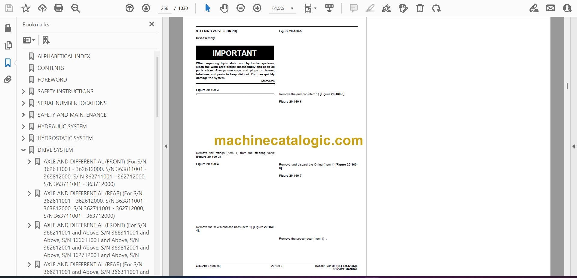
- STEERING VALVE
- Removal And Installation
- Parts Identification
- Disassembly
- Inspection
- Assembly
- HYDRAULIC CONTROL VALVE
- Troubleshooting Chart (Controllers)
- Telescopic Valve Section Troubleshooting
- Auxiliary Valve Section Troubleshooting
- Troubleshooting Chart (Control Valve)
- Removal And Installation
- Parts Identification
- Disassembly And Assembly
- End Housing Disassembly And Assembly
- Lifting Valve Section Disassembly And Assembly
- Tilting Valve Section Disassembly And Assembly
- Telescoping Valve Section Disassembly And Assembly
- Auxiliary/Frame Leveling Valve Section Disassembly And Assembly
- Inlet-Outlet Valve Section Disassembly And Assembly
- PORT RELIEF VALVES
- FLOW CONTROL VALVE
- JOYSTICK
- Removal And Installation
- Parts Identification
- PARKING BRAKE
- Parking Brake Valve Removal And Installation
- Parking Brake Valve Disassembly And Assembly
- PILOT PRESSURE LOCK OUT VALVE
- Testing
- Removal And Installation
- Disassembly And Assembly
- ACCUMULATOR
- OPTIONAL TOW VALVE
- Removal And Installation
- Disassembly And Assembly
- STABILIZER CYLINDER
- Removal And Installation
- Parts Identification
- Disassembly
- Assembly
- STABILIZER CONTROL VALVE
- Parts Identification
- Removal
- Assembly
- HYDROSTATIC SYSTEM
- HYDROSTATIC SYSTEM INFORMATION
- Troubleshooting Chart
- Replenishing Valve Function
- OIL COOLER
- HYDROSTATIC DRIVE MOTOR
- Removal And Installation
- Parts Identification
- Disassembly
- Inspection
- Assembly
- HYDROSTATIC PUMP
- Removal And Installation
- Parts Identification
- Disassembly
- Inspection
- Assembly
- Charge Pressure Checking Procedure
- Charge Pressure Adjusting Procedure
- DRIVE SYSTEM
- AXLE AND DIFFERENTIAL (FRONT) (For S/N 362611001 – 362612000, S/N 363811001 – 363812000, S/ N 362711001 – 362712000, S/N 363711001 – 363712000)
- General Information
- Planetary Carrier Parts Identification
- Planetary Carrier Disassembly
- Planetary Carrier Inspection
- Wheel Hub Parts Identification
- Wheel Hub Disassembly
- Wheel Hub Inspection
- Steering Knuckle Parts Identification
- Steering Knuckle Disassembly
- Axle Housing/Drive Axle Parts Identification
- Axle Housing/Drive Axle Disassembly
- Brake Group Parts Identification
- Brake Group Disassembly
- Brake Group Inspection
- Differential Parts Identification
- Differential Disassembly
- Differential Inspection
- Pinion Group Parts Identification
- Pinion Group Disassembly
- Pinion Group Inspection
- Pinion Group Assembly
- Differential Assembly
- Brake Group Assembly
- Axle Housing/Drive Axle Assembly
- Steering Knuckle Assembly
- Wheel Hub Assembly
- Planetary Carrier Assembly
- AXLE AND DIFFERENTIAL (REAR) (For S/N 362611001 – 362612000, S/N 363811001 – 363812000, S/N 362711001 – 362712000, S/N 363711001 – 363712000)
- General Information
- Planetary Carrier Parts Identification
- Planetary Carrier Disassembly
- Planetary Carrier Inspection
- Wheel Hub Parts Identification
- Wheel Hub Disassembly
- Wheel Hub Inspection
- Steering Knuckle Parts Identification
- Steering Knuckle Disassembly
- Axle Housing/Drive Axle Parts Identification
- Axle Housing/Drive Axle Disassembly
- Differential Parts Identification
- Differential Disassembly
- Differential Inspection
- Pinion Group Parts Identification
- Pinion Group Disassembly
- Pinion Group Inspection
- Pinion Group Assembly
- Differential Assembly
- Axle Housing/Drive Axle Assembly
- Steering Knuckle Assembly
- Wheel Hub Assembly
- Planetary Carrier Assembly
- AXLE AND DIFFERENTIAL (FRONT) (For S/N 366211001 and Above, S/N 366311001 and Above, S/N 366611001 and Above, S/N 362612001 and Above, S/N 363812001 and Above, S/N 362712001 and Above, S/N 363712001 and Above)
- General Information
- Planetary Carrier Parts Identification
- Planetary Carrier Disassembly
- Steering Knuckle and Drive Axle Parts Identification
- Steering Knuckle Disassembly
- Drive Axle Disassembly
- Brake system Identification
- Brake System Disassembly
- Differential Parts Identification
- Differential Disassembly
- Bevel pinion Parts Identification
- Bevel Pinion Disassembly
- Bevel Pinion Assembly
- Differential assembly
- Setting Ring And Pinion Backlash
- Brake System Assembly
- Drive Axle Assembly
- Steering Knuckle Assembly
- Planetary Carrier Assembly
- SPECIAL TOOLS
- AXLE AND DIFFERENTIAL (REAR) (For S/N 366211001 and Above, S/N 366311001 and Above, S/N 366611001 and Above, S/N 362612001 and Above, S/N 363812001 and Above, S/N 362712001 and Above, S/N 363712001 and Above)
- General Information
- Planetary Carrier Parts Identification
- Planetary Carrier Disassembly
- Steering Knuckle and Drive Axle Parts Identification
- Steering Knuckle Disassembly
- Differential and Bevel Pinion Parts Identification
- Differential Disassembly
- Bevel pinion Disassembly
- Bevel pinion Assembly
- Differential assembly
- Steering Knuckle Assembly
- Planetary Carrier Assembly
- Special tools
- FRONT AXLE (For S/N 362611001 – 362612000, S/N 363811001 – 363812000, S/N 362711001 – 362712000, S/ N 363711001 – 363712000)
- AXLE PIVOT FRAME (Only For S/N 362611001 -362612000, S/N 362711001 – 362712000)
- Removal And Installation
- Bushing Removal And Installation
- FRONT AXLE (For S/N 366211001 and Above, S/N 366311001 and Above, S/N 366611001 and Above, S/N 362612001 and Above, S/N 363812001 and Above, S/N 362712001 and Above, S/N 363712001 and Above)
- AXLE TOE-IN (For S/N 362611001 – 362612000, S/N 363811001 – 363812000, S/N 362711001 – 362712000, S/ N 363711001 – 363712000)
- AXLE TOE-IN (For S/N 366211001 and Above, S/N 366311001 and Above, S/N 366611001 and Above, S/N 362612001 and Above, S/N 363812001 and Above, S/N 362712001 and Above, S/N 363712001 and Above)
- PARKING BRAKE (For S/N 362611001 – 362612000, S/ N 363811001 – 363812000, S/N 362711001 – 362712000, S/N 363711001 – 363712000)
- Preparing For Towing
- Disengaging The Hydrostatic Transmission
- Releasing The Parking Brake
- Twing The Telescopic Handler
- PARKING BRAKE (For S/N 366211001 and Above, S/ N 366311001 and Above, S/N 366611001 and Above, S/N 362612001 and Above, S/N 363812001 and Above, S/N 362712001 and Above, S/N 363712001 and Above)
- Preparing For Towing
- Disengaging The Hydrostatic Transmission
- Releasing The Parking Brake
- Towing The Telescopic Handler
- STEERING ANGLE ADJUSTMENT (For S/N 362611001 – 362612000, S/N 363811001 – 363812000, S/N 362711001 – 362712000, S/N 363711001 – 363712000)
- STEERING ANGLE ADJUSTMENT (For S/N 366211001 and Above, S/N 366311001 and Above, S/N 366611001 and Above, S/N 362612001 and Above, S/N 363812001 and Above, S/N 362712001 and Above, S/N 363712001 and Above)
- DRIVESHAFT
- SERVICE BRAKE (For S/N 362611001 – 362612000, S/N 363811001 – 363812000, S/N 362711001 – 362712000, S/ N 363711001 – 363712000)
- Description
- Bleeding The Brake Circuit
- SERVICE BRAKE (For S/N 366211001 and Above, S/N 366311001 and Above, S/N 366611001 and Above, S/N 362612001 and Above, S/N 363812001 and Above, S/N 362712001 and Above, S/N 363712001 and Above)
- Description
- Bleeding The Brake Circuit
- REAR AXLE (For S/N 362611001 – 362612000, S/N 363811001 – 363812000, S/N 362711001 – 362712000, S/ N 363711001 – 363712000)
- REAR AXLE (For S/N 366211001 and Above, S/N 366311001 and Above, S/N 366611001 and Above, S/N 362612001 and Above, S/N 363812001 and Above, S/N 362712001 and Above, S/N 363712001 and Above)
- MAIN FRAME
- OPERATOR CAB
- OPERATOR SEAT
- FIXED BOOM
- END BOOM
- WEAR PADS (FRONT)
- WEAR PADS (REAR)
- ENGINE COVER
- Gas Cylinder Removal And Installation
- Removal And Installation
- AIR INTAKE COWLING
- FUEL TANK
- QUICK TACH
- REAR WEIGHTS
- FENDER
- DASH COVER/STEERING COLUMN COVER
- JOYSTICK PANEL
- BOOM TRAY
- INTERMEDIATE BOOM
- CHAIN CHECKING AND ADJUSTING PROCEDURE
- Checking/Adjustment Procedure
- STABILIZER FRAME
- ELECTRICAL SYSTEM AND ANALYSIS
- ELECTRICAL SYSTEM INFORMATION
- Troubleshooting Chart
- Description
- Fuses, Diodes & Relays
- BATTERY
- Removal And Installation
- Servicing
- Using A Booster Battery (Jump Starting)
- ALTERNATOR
- Removal And Installation
- Adjusting The Alternator Belt
- STARTER
- Removal And Installation
- Parts Identification
- Assembly/Disassembly
- LIGHTS
- Rear Light Removal And Installation
- Front Light Removal And Installation
- TRAVEL/SIGNAL LEVER
- INSTRUMENT PANEL
- SWITCH PANEL
- BRAKE LIGHT SWITCH
- Removal And Installation
- Adjustment
- FRONT WIPER MOTOR
- TOP WIPER MOTOR
- REAR WIPER MOTOR
- PEDAL ASSEMBLY
- Removal And Installation
- Disassembly And Assembly
- INCHING SWITCH
- Removal And Installation
- Adjustment
- SERVICE SOFTWARE
- Connecting The Laptop Computer
- Entering The Service Software
- Monitor Screen
- Warnings Screen
- Calibrate Inch Pedal
- FRAME LEVEL SPEED SWITCH
- Description
- Removal
- Installation
- LONGITUDINAL STABILITY INDICATOR CALIBRATION
- Fitting The Sensor
- Calibration Procedure
- ENGINE SERVICE
- TROUBLESHOOTING
- ENGINE SPEED CONTROL
- MUFFLER
- AIR CLEANER
- Housing Removal And Installation
- OIL COOLER/RADIATOR
- Removal And Installation
- Disassembly And Assembly
- ENGINE AND ENGINE MOUNTS
- ENGINE COMPONENTS AND TESTING
- Fuel Injection Pump Removal
- Fuel Injection Pump Installation
- Fuel Injectors Removal And Installation
- Checking The Fuel Lift Pump
- Fuel Lift Pump Removal And Installation
- Compression Checking
- Glow Plugs Checking
- Glow Plugs Removal And Installation
- ENGINE TIMING
- ENGINE/HYDROSTAT ASSEMBLY
- FLYWHEEL AND HOUSING
- RECONDITIONING THE ENGINE
- Turbo Charger Troubleshooting
- Turbo Charger Description
- Turbo Charger Removal And Installation
- Exhaust Manifold Removal And Installation
- Fuel Injector Cover Removal And Installation
- Rocker Cover Removal And Installation
- Cylinder Head Removal
- Cylinder Head Inspection
- Cylinder Head Installation
- Rocker Shaft Disassembly And Assembly
- Valve Removal
- Valve Springs Checking
- Valve Depth Checking
- Valve Guides Checking
- Valve Guide Removal
- Valve Guide Installation
- Valves Checking
- Cutting A Valve Seat
- Valve Seat Assembly
- Changing Valve Springs (With Cylinder Head Installed)
- Valve Clearance Adjustment
- Timing Case And Drive Assembly Description
- Timing Cover Removal
- Timing Cover Installation
- Crankshaft Pulley Removal And Installation
- Timing Case And Gear Removal
- Timing Case And Gear Installation
- Camshaft And Tappets Removal
- Camshaft And Tappets Installation
- Pistons And Connecting Rods Description
- Pistons And Connecting Rods Removal
- Pistons And Connecting Rods Disassembly
- Piston Ring End Gap
- Piston Ring Installation
- Piston Ring Groove Clearance
- Connecting Rod Inspection
- Connecting Rod Bushing Replacement
- Piston And Connecting Rod Assembly
- Piston And Connecting Rod Installation
- Crankshaft And Bearings Description
- Crankshaft And Bearings Removal
- Inspection Of Crankshaft And Bearings
- Crankshaft And Bearings Installation
- Rear Oil Seal Removal
- Rear Oil Seal Installation
- Checking Crankshaft End Play
- Cooling System Description
- Thermostat Removal And Installation
- Thermostat Testing
- Lubricating Oil Cooler Removal And Installation
- Water Pump Removal
- Water Pump Installation
- Engine Lubrication System Description
- Oil Filter Adapter Removal And Installation
- Oil Pan Removal And Installation
- Oil Screen And Pick-up Tube
- Oil Pump Installation
- Oil Pump Disassembly And Assembly
- Oil Pressure Relief Valve Disassembly And Assembly
- Engine Block Description
- Engine Block Disassembly And Assembly
- Piston Cooling Jet Removal
- Piston Cooling Jet Installation
- Piston Cooling Jet Alignment
- Inspection
- Cylinder Liner Inspection
- Cylinder Liner Removal
- Cylinder Liner Installation
- HEATING, VENTILATION, AIR CONDITIONING
- AIR CONDITIONING SYSTEM FLOW
- COMPONENTS
- SAFETY
- REGULAR MAINTENANCE
- Filter Element Removal And Installation
- Compressor Drive Belt Inspection
- Cleaning The Condenser
- BASIC TROUBLESHOOTING
- Poor A/C Performance
- Compressor Drive Belt Inspection
- Checking The Electrical System
- GENERAL AIR CONDITIONING SERVICE GUIDELINES
- Compressor Oil
- Compressor Oil Check
- Component Replacement And Refrigeration Leaks
- SYSTEM TROUBLESHOOTING CHART
- TEMPERATURE/PRESSURE
- AIR CONDITIONING SERVICE
- SYSTEM CHARGING AND RECLAMATION
- Reclamation Procedure
- Charging Procedure With A Manifold Gauge Set
- Charging Procedure
- COMPRESSOR
- Removal And Installation
- Compressor Clutch Disassembly And Assembly
- CONDENSER
- RECEIVER/DRIER
- PRESSURE SWITCH
- EVAPORATOR/BLOWER UNIT
- EXPANSION VALVE
- HEATER ASSEMBLY
- Removal And Installation
- Fan Removal And Installation
- Core Removal And Installation
- SPECIFICATIONS
- Telescopic Handler SPECIFICATIONS
- Dimensional Specifications
- Performance Specificaitons
- Engine
- Controls
- Drive System
- Tires
- Capacities
- Hydraulic System
- Electrical System
- Instrument Panel
- ENGINE SPECIFICATIONS
- General
- Cylinder Head
- Valve Guides
- Exhaust Valves
- Intake Valves
- Valve Springs
- Rocker Shaft, Rockers And Bushings
- Pistons And Piston Rings
- Connecting Rods And Bearings
- Crankshaft
- Crankshaft Re-Grind Data
- Main Bearings
- Thrust Washers
- Camshaft And Thrust Washer
- Cylinder Block
- Cylinder Liners
- Fuel Injection Pump
- Fuel Injectors
- Fuel Lift Pump
- Timing Case And Timing Gears
- Oil Pump, Gear And Relief Valve
- Turbocharger
- Flywheel
- Water Pump And Thermostat
- Engine Torque Component
- MACHINE TORQUE SPECIFICATIONS
- Axle
- Boom
- Drive Box
- Drive Motor
- Engine
- Hydraulic Pump
- TORQUE SPECIFICATIONS FOR BOLTS
- Torque For General SAE Bolts
- Torque For General Metric Bolts
- HYDRAULIC CONNECTION SPECIFICATIONS
- O-ring Face Seal Connection
- Straight Tread O-ring Fitting
- Tubelines And Hoses
- Flare Fitting
- O-ring Flare Fitting
- Port Seal Fitting
- HYDRAULIC/HYDROSTATIC FLUID SPECIFICATIONS
- CONVERSIONS
- Decimal And Millimeter Equivalents
- U.S. To Metric Conversion
- SERVICE MANUAL REVISION
- Revision No: T35100, T35100L, T35100SL, T35120L, T35120SL – 1
Bobcat Software
Bobcat PDF Manuals


