A TR35160 VersaHANDLER is a telescopic handler you'll see loading trucks, staging pallets, or placing materials where a skid steer just can't reach. The service manual is what the shop or field tech grabs when the boom quits, a hydraulic function is weak, or an electrical fault keeps it from starting. They're looking for step-by-step repair info, specs, and test procedures so the machine goes back out without a comeback.
What this manual helps you do
- Diagnose hydraulic issues on the boom and stabilizers, then check pressures and isolate bad valves or cylinders.
- Trace electrical faults in starting, charging, lights, and safety interlocks using wiring diagrams and test steps.
- Follow teardown and reassembly procedures for major components like the boom sections, drive axle, and steering system.
- Adjust and verify limit switches, load handling controls, and safety systems after repairs.
- Replace and set up wear items, hoses, and seals with the right sequences and spec references.
Who this is for
This is for anyone maintaining or repairing a Bobcat TR35160 VersaHANDLER TTC in the LLM1590000-LLM1599999 serial range: small contractors, owner-operators, rental fleets, and shop or field mechanics. If you just need basic controls, capacities, or daily checks, you want the operator's handbook, not this manual.
FAQ
Q: Is this a searchable PDF with readable wiring diagrams?
A: Yes, these manuals are normally supplied as searchable PDFs, and the wiring diagrams are laid out so you can zoom in and follow circuits clearly.
Q: Will this cover my exact TR35160 machine?
A: It's written for TR35160 VersaHANDLER TTC units in the LLM1590000-LLM1599999 serial range. If your plate is outside that, this isn't the right one.
Q: Is this the right document if I'm planning major repairs?
A: Yes, this is the workshop-level service manual, meant for real diagnostics and component repair, not just routine operation or parts lookup.
Bottom line: If your TR35160's serial number falls in that LLM1590000-LLM1599999 window and you're doing your own repairs, this is the manual you want. If the serial doesn't match, skip it.
📘 Show Index
Table of Contents:
- FOREWORD
- FOREWORD
- SAFETY INSTRUCTIONS
- Safe Operation Is The Operator’s Responsibility
- Safe Operation Needs A Qualified Operator
- Avoid Silica Dust
- Dismantling And Disposal
- FIRE PREVENTION
- Maintenance
- Operation
- Electrical
- Hydraulic System
- Fueling
- Starting
- Welding And Grinding
- Fire Extinguishers
- SERIAL NUMBER LOCATIONS
- Telescopic Handler Serial Numbers
- Engine Serial Number
- Other Serial Numbers
- DELIVERY REPORT
- BOBCAT TELESCOPIC HANDLER IDENTIFICATION
- TR35160
- TR45190, TR50210 And TR40250
- SAFETY & MAINTENANCE
- LIFTING AND BLOCKING THE TELESCOPIC HANDLER
- OPERATOR CAB
- Description
- Cab Door
- Cab Door Window
- Cab Rear Window
- Cab Light
- Cab Roof
- Cab Ventilation
- Rotating Beacon
- TRANSPORTING THE TELESCOPIC HANDLER
- TOWING THE TELESCOPIC HANDLER
- SERVICE SCHEDULE
- Chart
- Contents Of The Inspection Checkbook (Logbook)
- AIR CLEANER SERVICE (TR35160)
- AIR CLEANER SERVICE (TR45190, TR50210, TR40250)
- Cleaning And Replacing Cartridges
- Cleaning The Primary Intake Duct
- ENGINE COOLING SYSTEM
- Cleaning The Cooling System
- Checking The Coolant Level
- Removing And Replacing The Coolant
- FUEL SYSTEM
- Fuel Specifications
- Biodiesel Blend Fuel
- Filling The Fuel Tank
- Fuel Filters (TR35160)
- Fuel Filters (TR45190, TR50210, TR40250)
- Removing Air From The Fuel System
- Cleaning The Fuel Tank
- ENGINE LUBRICATION SYSTEM
- Checking And Adding Engine Oil (TR35160)
- Checking And Adding Engine Oil (TR45190, TR50210, TR40250)
- Engine Oil Chart
- Removing And Replacing Oil And Filter (TR35160)
- Removing And Replacing Oil And Filter (TR45190, TR50210, TR40250)
- HYDRAULIC / HYDROSTATIC SYSTEM
- Hydraulic / Hydrostatic Fluid Chart
- Checking And Adding Hydraulic / Hydrostatic Fluid
- Replacing Hydraulic / Hydrostatic Fluid And Filters
- AXLES (FRONT AND REAR)
- Checking And Adding Oil (Planetary Carrier)
- Removing And Replacing Oil (Planetary Carrier)
- Checking And Adding Oil (Front And Rear Differential)
- Removing And Replacing Oil (Front And Rear Differential)
- Checking And Adding Oil (Drive Box)
- Removing And Replacing Oil (Drive Box)
- LUBRICATING THE TELESCOPIC HANDLER
- Lubrication Locations
- Lubricating Telescopic Boom Wear Blocks
- Lubricating External Boom Chains
- TYRE MAINTENANCE
- Wheel Nuts
- Tyre Rotating
- Tyre Mounting
- Tyre Pressure
- ENGINE COVER
- APPROVED BOOM STOP
- Installing The Approved Boom Stop
- ANTI TIPPING DEVICE
- Description
- Main Work Data
- Complementary Work Data
- Attachment And Operating Mode
- Attachment Selection
- Unencoded Display Information
- Self-Diagnostics
- Anti Tipping Device Error Codes
- Remote Control Error Codes
- Diagnostics Displays
- Language Selection
- HYDRAULIC SYSTEM
- HYDRAULIC / HYDROSTATIC SCHEMATICS
- HYDRAULIC SYSTEM INFORMATION
- Troubleshooting Chart
- Tightening Procedures
- Hydraulic Component Pressures
- LIFT CYLINDER
- Removal And Installation
- Parts Identification
- Section View
- EXTENSION CYLINDER (TR45190, TR50210, TR40250)
- TILT CYLINDER
- DRIVE BOX
- Parts Identification
- Disassembly
- Assembly
- FRAME LEVELING CYLINDER (TR45190, TR50210, TR40250)
- BRAKE AND GEAR VALVES
- STEERING MODE VALVE BLOCK
- STEERING VALVE
- HYDRAULIC CONTROL VALVE (TR45190 (EARLIER MODELS), TR50210 (EARLIER MODELS) AND TR40250 (EARLIER MODELS))
- Parts Identification
- Valve Section Identification
- Lifting Valve Section
- Upperstructure Swing Valve Section
- Telescoping Valve Section
- Tilting Valve Section
- Auxiliary Valve Section
- Inlet-outlet Valve Section
- End Housing
- HYDRAULIC CONTROL VALVE (TR35160, TR45190 (LATER MODELS), TR50210 (LATER MODELS) AND TR40250 (LATER MODELS))
- Parts Identification
- Valve Section Identification
- Module Valve Section
- Lifting Valve Section
- Upperstructure Swing Valve Section
- Telescoping Valve Section
- Interface Valve Section
- Tilting Valve Section
- Auxiliary Valve Section
- SWING MOTOR (TR35160)
- Parts Identification
- Checking, Adding or Replacing Oil
- SWING MOTOR (TR45190, TR50210, TR40250)
- Parts Identification
- Checking, Adding or Replacing Oil
- SWIVEL JOINT
- STABILISER CYLINDER (TR45190, TR50210, TR40250)
- STABILISER EXTENSION CYLINDER (TR45190, TR50210, TR40250)
- REAR AXLE OSCILLATION LOCK CYLINDER
- STABILISER / LEVELLING VALVE
- HYDROSTATIC SYSTEM
- HYDROSTATIC DRIVE MOTOR
- HYDROSTATIC PUMP
- HYDROSTATIC TRANSMISSION ADJUSTMENT
- Description
- Starting Adjustment
- Feeding Pressure
- Hydrostatic Pump Pressure
- Hydrostatic Motor Pressure
- DRIVE SYSTEM
- TROUBLESHOOTING
- AXLE AND DIFFERENTIAL (FRONT)
- General Information
- Planetary Carrier Parts Identification
- Planetary Carrier Disassembly
- Steering Cylinder Parts Identification
- Steering Cylinder Removal
- Steering Cylinder Disassembly
- Steering Case Parts Identification
- Steering Case Disassembly
- Drive Axle Parts Identification
- Drive Axle Disassembly
- Brake System Parts Identification
- Brake System Disassembly
- Hydraulic Differential Lock Parts Identification
- Hydraulic Differential Lock Disassembly
- Differential Unit (Limited Slip) Parts Identification
- Differential Unit (Limited Slip) Disassembly
- Bevel Pinion Parts Identification
- Bevel Pinion Removal
- Bevel Pinion Installation And Adjustment
- Differential Unit (Limited Slip) Assembly
- Hydraulic Differential Lock Assembly
- Brake System Assembly
- Drive Axle Assembly
- Steering Case Assembly
- Steering Cylinder Assembly
- Steering Cylinder Installation
- Planetary Carrier Assembly
- Special Tools
- AXLE AND DIFFERENTIAL (REAR)
- General Information
- Planetary Carrier Parts Identification
- Planetary Carrier Disassembly
- Steering Cylinder Parts Identification
- Steering Cylinder Removal
- Steering Cylinder Disassembly
- Steering Case Parts Identification
- Steering Case Disassembly
- Drive Axle Parts Identification
- Drive Axle Disassembly
- Negative Brake Parts Identification
- Negative Brake Disassembly
- Hydraulic Differential Lock Parts Identification
- Hydraulic Differential Lock Disassembly
- Differential Unit (Limited Slip) Parts Identification
- Differential Unit (Limited Slip) Disassembly
- Bevel Pinion Parts Identification
- Bevel Pinion Removal
- Bevel Pinion Installation And Adjustment
- Differential Unit (Limited Slip) Assembly
- Hydraulic Differential Lock Assembly
- Negative Brake Assembly
- Drive Axle Assembly
- Steering Case Assembly
- Steering Cylinder Assembly
- Steering Cylinder Installation
- Planetary Carrier Assembly
- Special Tools
- ELECTRICAL SYSTEM AND ANALYSIS
- ELECTRICAL SCHEMATICS
- ELECTRICAL SYSTEM INFORMATION
- Troubleshooting Chart
- Fuse And Relay Location / Identification
- BATTERY
- Removal And Installation
- Battery Disconnect Switch
- Servicing
- Using A Booster Battery (Jump Starting)
- Battery Test
- ALTERNATOR (TR45190, TR50210, TR40250)
- Alternator Removal (Engines Without An Automatic Belt Tensioner)
- Alternator Installation (Engines Without An Automatic Belt Tensioner)
- Alternator Removal (Engines With An Automatic Belt Tensioner)
- Alternator Installation (Engines With An Automatic Belt Tensioner)
- Alternator Test
- Charging System Test
- STARTER (TR45190, TR50210, TR40250)
- Electric Starting Motor Removal
- Electric Starting Motor Installation
- Electric Starting System Test
- SENSORS AND SWITCHES
- Stabilisers Extended And Lowered (TR45190, TR50210, TR40250)
- Stabilisers Lowered (TR35160)
- Upperstructure Aligned With Undercarriage
- Upperstructure Rotated 174° (TR35160)
- Upperstructure Slew Lock Inserted
- Axle Oscillation Lock Range (12°)
- Boom Raised / Lowered And Extended / Retracted Completely (TR45190, TR50210, TR40250)
- Boom Raised / Lowered Completely (TR35160)
- MAN PLATFORM LOAD LIMITER CALIBRATION
- ENGINE SERVICE
- GENERAL ALARM PILOT LIGHT (TR45190, TR50210, TR40250)
- Engine Errors
- Centre Indicator And Instrument Panel Pilot Lights
- Engine Over-Revs
- Engine Error Codes
- Error Menu
- SERVICE (TR45190, TR50210, TR40250)
- SENSORS AND ELECTRICAL COMPONENTS (TR45190, TR50210, TR40250)
- Sensor Locations
- Failure Of Sensors
- Programmable Monitoring System (PMS)
- Coolant Temperature Sensor
- Boost Pressure Sensor
- Inlet Air Temperature Sensor
- Fuel Pressure Sensor
- Crankshaft Position Sensor
- Position Sensor For The Fuel Injection Pump
- Engine Oil Pressure Sensor
- ENGINE COMPONENTS AND TESTING (TR45190, TR50210, TR40250)
- Fuel Priming Pump Removal (Electric Fuel Priming Pump)
- Fuel Priming Pump Installation (Electric Fuel Priming Pump)
- Fuel Priming Pump Removal (Manual Fuel Priming Pump)
- Fuel Priming Pump Installation (Manual Fuel Priming Pump)
- Fuel Filter Base Removal (Secondary Fuel Filter)
- Fuel Filter Base Installation (Secondary Fuel Filter)
- Fuel Transfer Pump Removal
- Fuel Transfer Pump Installation
- Fuel Injection Lines Removal
- Fuel Injection Lines Installation
- Fuel Manifold (Rail) Removal
- Fuel Manifold (Rail) Installation
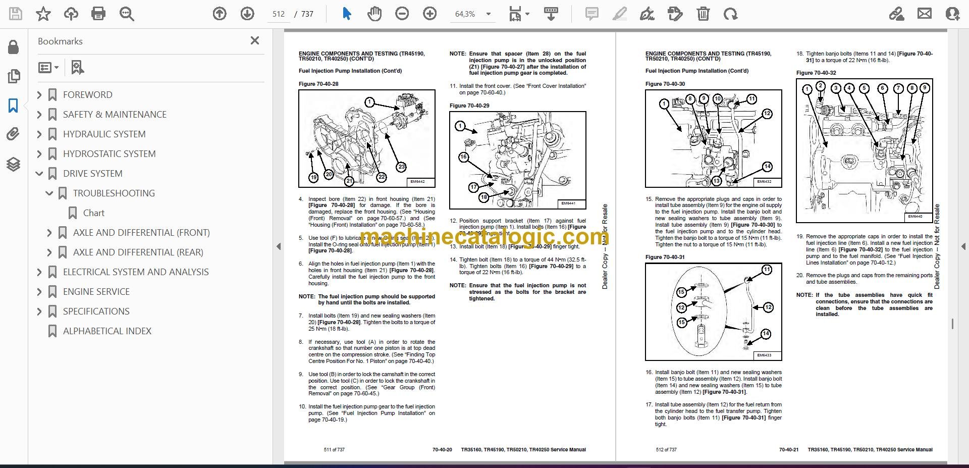
- Fuel Injection Pump Removal
- Fuel Injection Pump Installation
- Fuel Injection Pump Gear Removal
- Fuel Injection Pump Gear Installation
- Position Sensor (Fuel Injection Pump) Removal
- Position Sensor (Fuel Injection Pump) Installation
- Fuel Pressure Sensor Removal
- Fuel Pressure Sensor Installation
- Boost Pressure Sensor Removal
- Boost Pressure Sensor Installation
- Electronic Unit Injector Removal
- Electronic Unit Injector Installation
- Electronic Unit Injector Installation (Alternative Installation Procedure)
- Lifter Group Removal
- Lifter Group Installation
- Fuel System Inspection
- Air In Fuel Test
- Finding Top Centre Position For No. 1 Piston
- Fuel Injection Timing Check
- Fuel Quality Test
- Fuel System Prime
- Compression Test
- Glow Plugs Removal
- Glow Plugs Installation
- Glow Plugs Test
- FLYWHEEL AND HOUSING (TR45190, TR50210, TR40250)
- Flywheel Removal
- Flywheel Installation
- Flywheel Inspection
- Flywheel Housing Removal
- Flywheel Housing Installation
- Flywheel Housing Inspection
- RECONDITIONING THE ENGINE (TR45190, TR50210, TR40250)
- Turbo Charger Removal
- Turbo Charger Installation
- Turbo Charger Inspection
- Wastegate Solenoid Removal
- Wastegate Solenoid Installation
- Exhaust Manifold Removal
- Exhaust Manifold Installation
- Exhaust Elbow Removal
- Exhaust Elbow Installation
- Valve Mechanism Cover Removal
- Valve Mechanism Cover Installation
- Valve Mechanism Cover Base Removal
- Valve Mechanism Cover Base Installation
- Cylinder Head Removal
- Cylinder Head Installation
- Cylinder Head Inspection
- Cylinder Block Inspection
- Rocker Shaft And Pushrod Removal
- Rocker Shaft And Pushrod Installation
- Rocker Shaft Disassembly
- Rocker Shaft Assembly
- Inlet And Exhaust Valves Removal
- Inlet And Exhaust Valves Installation
- Air Inlet And Exhaust System Inspection
- Engine Valve Lash Inspection / Adjustment
- Valve Depth Inspection
- Valve Guide Inspection
- Inlet And Exhaust Valve Springs Removal
- Inlet And Exhaust Valve Springs Installation
- Front Cover Removal
- Front Cover Installation
- Crankshaft Pulley Removal (Engines With An Automatic Belt Tensioner)
- Crankshaft Pulley Installation (Engines With An Automatic Belt Tensioner)
- Crankshaft Pulley Removal (Engines Without An Automatic Belt Tensioner)
- Crankshaft Pulley Installation (Engines Without An Automatic Belt Tensioner)
- Crankshaft Pulley Check
- Gear Group (Front) Removal
- Gear Group (Front) Installation
- Gear Group (Front) Timing
- Gear Group Inspection
- Idler Gear Removal (Standard Idler Gear)
- Idler Gear Installation (Standard Idler Gear)
- Idler Gear Removal (Heavy-Duty Idler Gear)
- Idler Gear Installation (Heavy-Duty Idler Gear)
- Housing (Front) Removal
- Housing (Front) Installation
- Accessory Drive Removal
- Accessory Drive Installation
- Crankcase Breather Removal (Filtered Breather)
- Crankcase Breather Installation (Filtered Breather)
- Crankcase Breather Removal (Unfiltered Breather)
- Crankcase Breather Installation (Unfiltered Breather)
- Camshaft Removal
- Camshaft Installation
- Camshaft Gear Removal
- Camshaft Gear Installation
- Camshaft Bearings Removal
- Camshaft Bearings Installation
- Pistons And Connecting Rods Removal
- Pistons And Connecting Rods Installation
- Pistons And Connecting Rods Disassembly
- Pistons And Connecting Rods Assembly
- Piston Ring Groove Inspection
- Connecting Rod Inspection
- Connecting Rod Bearings Removal (Connecting Rods In Position)
- Connecting Rod Bearings Installation (Connecting Rods In Position)
- Piston Height Inspection
- Crankshaft Main Bearings Removal (Crankshaft In Position)
- Crankshaft Main Bearings Installation (Crankshaft In Position)
- Crankshaft Removal
- Crankshaft Installation
- Crankshaft Timing Ring Removal
- Crankshaft Timing Ring Installation
- Crankshaft Gear Removal
- Crankshaft Gear Installation
- Bearing Clearance Check
- Crankshaft Position Sensor Removal
- Crankshaft Position Sensor Installation
- Crankshaft Rear Seal Removal
- Crankshaft Rear Seal Installation
- Crankshaft Wear Sleeve (Rear) Removal
- Crankshaft Wear Sleeve (Rear) Installation
- Crankshaft Front Seal Removal
- Crankshaft Front Seal Installation
- Crankshaft Wear Sleeve (Front) Removal
- Crankshaft Wear Sleeve (Front) Installation
- Water Temperature Regulator Removal
- Water Temperature Regulator Installation
- Water Temperature Regulator Test
- Coolant Temperature Sensor Removal
- Coolant Temperature Sensor Installation
- Cooling System Check
- Cooling System Inspection
- Water Pump Removal
- Water Pump Installation
- Water Pump Inspection
- Engine Oil Filter Base Removal
- Engine Oil Filter Base Installation
- Engine Oil Cooler Removal
- Engine Oil Cooler Installation
- Engine Oil Cooler Inspection
- Engine Oil Relief Valve Removal (Engines With A Balancer Unit)
- Engine Oil Relief Valve Installation (Engines With A Balancer Unit)
- Engine Oil Relief Valve Removal (Engines Without A Balancer Unit)
- Engine Oil Relief Valve Installation (Engines Without A Balancer Unit)
- Engine Oil Pump Removal (Engines Without A Balancer Unit)
- Engine Oil Pump Installation (Engines Without A Balancer Unit)
- Engine Oil Pump Inspection
- Engine Oil Pan Removal (Aluminium And Pressed Steel Oil Pans)
- Engine Oil Pan Installation (Aluminium And Pressed Steel Oil Pans)
- Engine Oil Pan Removal (Cast Iron Oil Pan)
- Engine Oil Pan Installation (Cast Iron Oil Pan)
- Engine Oil Pressure Sensor Removal
- Engine Oil Pressure Sensor Installation
- Engine Oil Pressure Test
- Excessive Engine Oil Consumption Inspection
- Increased Engine Oil Temperature Inspection
- Excessive Bearing Wear Inspection
- Balancer Removal
- Balancer Installation
- Balancer Disassembly
- Balancer Assembly
- Piston Cooling Jets Removal
- Piston Cooling Jets Installation
- Inlet Air Temperature Sensor Removal
- Inlet Air Temperature Sensor Installation
- V-belts Removal (Engines Without An Automatic Belt Tensioner)
- V-belts Installation (Engines Without An Automatic Belt Tensioner)
- V-belt Test
- Alternator Belt Removal (Engines With An Automatic Belt Tensioner)
- Alternator Belt Installation (Engines With An Automatic Belt Tensioner)
- Fan Removal
- Fan Installation
- Fan Drive Removal
- Fan Drive Installation
- Electronic Control Module Removal
- Electronic Control Module Installation
- ECM Mounting Bracket Removal
- ECM Mounting Bracket Installation
- Air Compressor Removal
- Air Compressor Installation
- Vacuum Pump Removal
- Vacuum Pump Installation
- SPECIFICATIONS
- (TR35160, TR45190, TR50210, TR40250) TELESCOPIC HANDLER SPECIFICATIONS
- Machine Dimensions
- Performance
- Engine
- Transmission
- Hydraulic System
- Differential Axles
- Capacities
- Tyres
- Environmental
- ENGINE SPECIFICATIONS (TR45190, TR50210, TR40250)
- General
- Fuel Transfer Pump
- Electric Fuel Priming Pump
- Lifter Group
- Rocker Shaft
- Cylinder Head Valves
- Cylinder Head
- Turbo Charger
- Camshaft
- Camshaft Bearings
- Engine Oil Pump – Engines With Balancer Group
- Engine Oil Pressure
- Engine Oil Bypass Valve – Installed In The Oil Pump
- Engine Oil Bypass Valve – Installed In The Balancer
- Water Temperature Regulator And Housing
- Cylinder Block
- Crankshaft
- Crankshaft Journals
- Connecting Rod Bearing Journal
- Main Bearing Journal
- Shell For The Main Bearings
- Connecting Rod
- Piston And Rings – Rings
- Piston And Rings – Piston
- Piston And Rings – Oversize Piston
- Piston Cooling Jet Alignment
- Front Housing And Covers
- Gear Group (Front)
- Flywheel
- Belt Tension Chart
- Alternator
- Engine Torque Values
- TORQUE SPECIFICATIONS FOR BOLTS
- Torque for General SAE Bolts
- Torque For General Metric Bolts
- HYDRAULIC CONNECTION SPECIFICATIONS
- O-ring Face Seal Connection
- Straight Thread O-ring Fitting
- Tubelines And Hoses
- Flare Fitting
- O-ring Flare Fitting
- Port Seal Fitting
- CONVERSIONS
- Decimal And Millimeter Equivalents
- U.S. To Metric Conversion Chart
- SERVICE TOOLS REQUIRED
- Remote Start Tools
- Hydraulic Tools
- Drive Tools
- Electrical Tools
- Engine Tools
- HVAC Tools
- ALPHABETICAL INDEX
Bobcat Software
Bobcat PDF Manuals


