On a real job, this T35120 VersaHANDLER is your telehandler for lifting pallets, setting trusses, and placing material where a skid-steer just can't reach. The service manual is what you grab when the boom won't extend right, hydraulics act up, or an electrical gremlin kills your day. Around my shop, I reach for this kind of manual when downtime is costing more than the repair and I need the exact procedure, not guesses from the internet.
What this manual helps you do
- Diagnose hydraulic issues on the boom and stabilizers, then check pressures and cylinder operation in the right order
- Trace and troubleshoot electrical faults using wiring diagrams, from dead joysticks to sensor and relay problems
- Follow teardown and reassembly steps for major components like the boom sections, drive system, and steering circuits
- Set and verify adjustments on linkages, valves, and safety interlocks so the machine lifts and travels the way it should
- Replace seals, hoses, and wear parts with the correct disassembly sequence so you don't damage expensive castings
Who this is for
This is for a small contractor, shop mechanic, rental fleet, or owner-operator running a Bobcat T35120 VersaHANDLER TTC in the serial range 362711001 to 362799999. If you only want basic controls, capacities, or daily checks, you want the operator's handbook instead, not this service manual.
FAQ
Q: Is this a searchable PDF and are the wiring diagrams readable?
A: Yes, these manuals are usually supplied as searchable PDF files, and the wiring diagrams are laid out so you can zoom in and read pin labels.
Q: How do I know if it fits my machine?
A: Check your serial tag. If your T35120 VersaHANDLER TTC serial falls between 362711001 and 362799999, this is the right manual.
Q: Is this the right document if I'm doing real repairs, not just maintenance?
A: Yes, this is the workshop-level service manual, meant for actual troubleshooting, teardown, and repair, not just routine service.
Bottom line: If your T35120's serial is in that range and you're doing your own repairs, this is the manual you want. If your serial is outside that range, skip it.
📘 Show Index
Table of Contents:
- ALPHABETICAL INDEX
- CONTENTS
- FOREWORD
- SAFETY INSTRUCTIONS
- Before Operation
- Safe Operation Is The Operator’s Responsibility
- Safe Operation Needs A Qualified Operator
- SERIAL NUMBER LOCATIONS
- Telescopic Handler Serial Number
- Engine Serial Number
- Other Serial Numbers
- Delivery Report
- Identification of the telescopic handler
- SAFETY AND MAINTENANCE
- LIFTING AND BLOCKING THE TELESCOPIC HANDLER
- OPERATOR CAB
- Emergency Exit
- Cab Door
- Cab Door Window
- TRANSPORTING THE TELESCOPIC HANDLER
- TOWING THE TELESCOPIC HANDLER
- Preparing for towing
- Disengaging the hydrostatic transmission
- Releasing the handbrake (For S/N 362611001 – 362612000, S/N 363811001 – 363812000, S/N 362711001 – 362712000, S/N 363711001 – 363712000):
- Releasing the handbrake (For S/N 366211001 and Above, S/N 366311001 and Above, S/N 366611001 and Above, S/N 362612001 and Above, S/N 363812001 and Above, S/N 362712001 and Above, S/N 363712001 and Above):
- Towing The Telescopic Handler
- SERVICE SCHEDULE
- AIR CLEANER SERVICE
- ENGINE COOLING SYSTEM
- Cleaning The Cooling System
- Checking The Coolant Level
- Replacing The Coolant
- FUEL SYSTEM
- Fuel Specifications
- Fuel Filter
- ENGINE LUBRICATION SYSTEM
- Checking Engine Oil
- Oil Chart
- Replacing Oil And Filter
- HYDRAULIC/HYDROSTATIC SYSTEM
- Checking And Adding Fluid
- Replacing Hydraulic/Hydrostatic Filter
- Replacing Hydraulic Fluid
- AXLES (FRONT AND REAR) (For S/N 362611001 – 362612000, S/N 363811001 – 363812000, S/N 362711001 – 362712000, S/N 363711001 – 363712000)
- Checking Oil Level (Planetary Carrier)
- Draining Oil (Planetary Carrier)
- Checking Oil Level (Rear Differential)
- Draining Oil (Rear Differential)
- Checking Oil Level (Front
Differential)
- Draining Oil (Front Differential)
- AXLES (FRONT AND REAR) (For S/N 366211001 and Above, S/N 366311001 and Above, S/N 366611001 and Above, S/N 362612001 and Above, S/N 363812001 and Above, S/N 362712001 and Above, S/N 363712001 and Above)
- Checking Oil Level (
Planetary Carrier)
- Draining Oil (Planetary Carrier)
- Checking Oil Level (Rear Differential)
- Draining Oil (Rear Differential)
- Checking Oil Level (Front Differential)
- Draining Oil (Front Differential)
- LUBRICATION (For S/N 362611001 – 362612000, S/N 363811001 – 363812000, S/N 362711001 – 362712000, S/ N 363711001 – 363712000)
- LUBRICATION (For S/N 366211001 and Above, S/N 366311001 and Above, S/N 366611001 and Above, S/N 362612001 and Above, S/N 363812001 and Above, S/N 362712001 and Above, S/N 363712001 and Above)
- ATTACHMENT FRAME
- Inspection And Maintenance
- ATTACHMENT FRAME
- Inspection And Maintenance
- TIRE MAINTENANCE
- Wheel Nuts
- Tire Rotation
- Tire Mounting
- OPTIONAL APPROVED BOOM STOP
- Installing The Approved Boom Stop
- ENGINE COVER
- Opening And Closing The Engine Cover
- CHAIN CHECKING AND ADJUSTING PROCEDURE
- Checking/Adjustment Procedure
- HYDRAULIC SYSTEM
- HYDRAULIC SYSTEM INFORMATION
- Troubleshooting Chart
- Tightening Procedures
- LIFT CYLINDER
- Removal And Installation
- Parts Identification
- Disassembly
- Assembly
- BUCKET POSITIONING CYLINDER
- Removal And Installation
- Parts Identification
- Disassembly
- Assembly
- EXTENSION CYLINDER
- Cylinder Group Removal And Installation
- Parts Identification
- Disassembly
- Assembly
- TILT CYLINDER
- Removal And Installation
- Parts Identification
- Disassembly
- Assembly
- STEERING CYLINDER (FRONT) (For S/N 362611001 – 362612000, S/N 362711001 – 362712000)
- Removal And Installation
- Parts Identification
- Disassembly
- Assembly
- STEERING CYLINDER (FRONT) (For S/N 366211001 and Above, S/N 366311001 and Above, S/N 366611001 and Above, S/N 362612001 and Above, S/N 363812001 and Above, S/N 362712001 and Above, S/N 363712001 and Above)
- Removing The Steering Cylinder
- Installing The Steering Cylinder
- Disassembling The Steering Cylinder
- Assembling The Steering Cylinder
- STEERING CYLINDER (REAR) (For S/N 362611001 – 362612000, S/N 362711001 – 362712000)
- Removal And Installation
- Parts Identification
- Disassembly
- Assembly
- STEERING CYLINDER (REAR) (For S/N 366211001 and Above, S/N 366311001 and Above, S/N 366611001 and Above, S/N 362612001 and Above, S/N 363812001 and Above, S/N 362712001 and Above, S/N 363712001 and Above)
- Removing The Steering Cylinder
- Installing The Steering Cylinder
- Disassembling The Steering Cylinder
- Assembling The Steering Cylinder
- DRIVE BOX (For S/N 362611001 – 362612000, S/N 362711001 – 362712000)
- Parts Identification
- Disassembly
- Inspection
- Assembly
- DRIVE BOX (For S/N 366211001 and Above, S/N 366311001 and Above, S/N 366611001 and Above, S/N 362612001 and Above, S/N 363812001 and Above, S/N 362712001 and Above, S/N 363712001 and Above)
- Parts Identification
- Disassembly
- Assembly
- Special Tools
- MAIN RELIEF VALVE
- QUICK TACH CYLINDER
- Removal And Installation
- Parts Identification
- Disassembly
- Assembly
- FRAME LEVELING CYLINDER
- Removal And Installation (FOR S/N 362611001 -362612000, S/N 362711001 – 362712000)
- Removal And Installation (For S/N 366211001 andAbove, S/N 366311001 and Above, S/N 366611001 andAbove, S/N 362612001 and Above, S/N 363812001and Above, S/N 362712001 and Above, S/N 363712001and Above)
- Removal
- Parts Identification
- Disassembly
- Assembly
- STEERING MODE VALVE BLOCK
- Removal And Installation
- Parts Identification
- Disassembly
- Solenoid Testing
- Assembly
- BRAKE VALVE
- Removal And Installation
- Disassembly And Assembly
- GEAR PUMP
- Removal And Installation
- Parts Identification
- Disassembly And Assembly
- FAN MOTOR
- Removal And Installation
- Parts Identification
- Disassembly And Assembly (1 Speed Version)
- Disassembly And Assembly (2 Speed Version)
- HYDRAULIC RESERVOIR
- STEERING VALVE
- Removal And Installation
- Parts Identification
- Disassembly
- Inspection
- Assembly
- HYDRAULIC CONTROL VALVE
- Troubleshooting Chart (Controllers)
- Telescopic Valve Section Troubleshooting
- Auxiliary Valve Section Troubleshooting
- Troubleshooting Chart (Control Valve)
- Removal And Installation
- Parts Identification
- Disassembly And Assembly
- End Housing Disassembly And Assembly
- Lifting Valve Section Disassembly And Assembly
- Tilting Valve Section Disassembly And Assembly
- Telescoping Valve Section Disassembly And Assembly
- Auxiliary/Frame Leveling Valve Section Disassembly And Assembly
- Inlet-Outlet Valve Section Disassembly And Assembly
- PORT RELIEF VALVES
- FLOW CONTROL VALVE
- JOYSTICK
- Removal And Installation
- Parts Identification
- PARKING BRAKE
- Parking Brake Valve Removal And Installation
- Parking Brake Valve Disassembly And Assembly
- PILOT PRESSURE LOCK OUT VALVE
- Testing
- Removal And Installation
- Disassembly And Assembly
- ACCUMULATOR
- OPTIONAL TOW VALVE
- Removal And Installation
- Disassembly And Assembly
- STABILIZER CYLINDER
- Removal And Installation
- Parts Identification
- Disassembly
- Assembly
- STABILIZER CONTROL VALVE
- Parts Identification
- Removal
- Assembly
- HYDROSTATIC SYSTEM
- HYDROSTATIC SYSTEM INFORMATION
- Troubleshooting Chart
- Replenishing Valve Function
- OIL COOLER
- HYDROSTATIC DRIVE MOTOR
- Removal And Installation
- Parts Identification
- Disassembly
- Inspection
- Assembly
- HYDROSTATIC PUMP
- Removal And Installation
- Parts Identification
- Disassembly
- Inspection
- Assembly
- Charge Pressure Checking Procedure
- Charge Pressure Adjusting Procedure
- DRIVE SYSTEM
- AXLE AND DIFFERENTIAL (FRONT) (For S/N 362611001 – 362612000, S/N 363811001 – 363812000, S/ N 362711001 – 362712000, S/N 363711001 – 363712000)
- General Information
- Planetary Carrier Parts Identification
- Planetary Carrier Disassembly
- Planetary Carrier Inspection
- Wheel Hub Parts Identification
- Wheel Hub Disassembly
- Wheel Hub Inspection
- Steering Knuckle Parts Identification
- Steering Knuckle Disassembly
- Axle Housing/Drive Axle Parts Identification
- Axle Housing/Drive Axle Disassembly
- Brake Group Parts Identification
- Brake Group Disassembly
- Brake Group Inspection
- Differential Parts Identification
- Differential Disassembly
- Differential Inspection
- Pinion Group Parts Identification
- Pinion Group Disassembly
- Pinion Group Inspection
- Pinion Group Assembly
- Differential Assembly
- Brake Group Assembly
- Axle Housing/Drive Axle Assembly
- Steering Knuckle Assembly
- Wheel Hub Assembly
- Planetary Carrier Assembly
- AXLE AND DIFFERENTIAL (REAR) (For S/N 362611001 – 362612000, S/N 363811001 – 363812000, S/N 362711001 – 362712000, S/N 363711001 – 363712000)
- General Information
- Planetary Carrier Parts Identification
- Planetary Carrier Disassembly
- Planetary Carrier Inspection
- Wheel Hub Parts Identification
- Wheel Hub Disassembly
- Wheel Hub Inspection
- Steering Knuckle Parts Identification
- Steering Knuckle Disassembly
- Axle Housing/Drive Axle Parts Identification
- Axle Housing/Drive Axle Disassembly
- Differential Parts Identification
- Differential Disassembly
- Differential Inspection
- Pinion Group Parts Identification
- Pinion Group Disassembly
- Pinion Group Inspection
- Pinion Group Assembly
- Differential Assembly
- Axle Housing/Drive Axle Assembly
- Steering Knuckle Assembly
- Wheel Hub Assembly
- Planetary Carrier Assembly
- AXLE AND DIFFERENTIAL (FRONT) (For S/N 366211001 and Above, S/N 366311001 and Above, S/N 366611001 and Above, S/N 362612001 and Above, S/N 363812001 and Above, S/N 362712001 and Above, S/N 363712001 and Above)
- General Information
- Planetary Carrier Parts Identification
- Planetary Carrier Disassembly
- Steering Knuckle and Drive Axle Parts Identification
- Steering Knuckle Disassembly
- Drive Axle Disassembly
- Brake system Identification
- Brake System Disassembly
- Differential Parts Identification
- Differential Disassembly
- Bevel pinion Parts Identification
- Bevel Pinion Disassembly
- Bevel Pinion Assembly
- Differential assembly
- Setting Ring And Pinion Backlash
- Brake System Assembly
- Drive Axle Assembly
- Steering Knuckle Assembly
- Planetary Carrier Assembly
- SPECIAL TOOLS
- AXLE AND DIFFERENTIAL (REAR) (For S/N 366211001 and Above, S/N 366311001 and Above, S/N 366611001 and Above, S/N 362612001 and Above, S/N 363812001 and Above, S/N 362712001 and Above, S/N 363712001 and Above)
- General Information
- Planetary Carrier Parts Identification
- Planetary Carrier Disassembly
- Steering Knuckle and Drive Axle Parts Identification
- Steering Knuckle Disassembly
- Differential and Bevel Pinion Parts Identification
- Differential Disassembly
- Bevel pinion Disassembly
- Bevel pinion Assembly
- Differential assembly
- Steering Knuckle Assembly
- Planetary Carrier Assembly
- Special tools
- FRONT AXLE (For S/N 362611001 – 362612000, S/N 363811001 – 363812000, S/N 362711001 – 362712000, S/ N 363711001 – 363712000)
- AXLE PIVOT FRAME (Only For S/N 362611001 -362612000, S/N 362711001 – 362712000)
- Removal And Installation
- Bushing Removal And Installation
- FRONT AXLE (For S/N 366211001 and Above, S/N 366311001 and Above, S/N 366611001 and Above, S/N 362612001 and Above, S/N 363812001 and Above, S/N 362712001 and Above, S/N 363712001 and Above)
- AXLE TOE-IN (For S/N 362611001 – 362612000, S/N 363811001 – 363812000, S/N 362711001 – 362712000, S/ N 363711001 – 363712000)
- AXLE TOE-IN (For S/N 366211001 and Above, S/N 366311001 and Above, S/N 366611001 and Above, S/N 362612001 and Above, S/N 363812001 and Above, S/N 362712001 and Above, S/N 363712001 and Above)
- PARKING BRAKE (For S/N 362611001 – 362612000, S/ N 363811001 – 363812000, S/N 362711001 – 362712000, S/N 363711001 – 363712000)
- Preparing For Towing
- Disengaging The Hydrostatic Transmission
- Releasing The Parking Brake
- Twing The Telescopic Handler
- PARKING BRAKE (For S/N 366211001 and Above, S/ N 366311001 and Above, S/N 366611001 and Above, S/N 362612001 and Above, S/N 363812001 and Above, S/N 362712001 and Above, S/N 363712001 and Above)
- Preparing For Towing
- Disengaging The Hydrostatic Transmission
- Releasing The Parking Brake
- Towing The Telescopic Handler
- STEERING ANGLE ADJUSTMENT (For S/N 362611001 – 362612000, S/N 363811001 – 363812000, S/N 362711001 – 362712000, S/N 363711001 – 363712000)
- STEERING ANGLE ADJUSTMENT (For S/N 366211001 and Above, S/N 366311001 and Above, S/N 366611001 and Above, S/N 362612001 and Above, S/N 363812001 and Above, S/N 362712001 and Above, S/N 363712001 and Above)
- DRIVESHAFT
- SERVICE BRAKE (For S/N 362611001 – 362612000, S/N 363811001 – 363812000, S/N 362711001 – 362712000, S/ N 363711001 – 363712000)
- Description
- Bleeding The Brake Circuit
- SERVICE BRAKE (For S/N 366211001 and Above, S/N 366311001 and Above, S/N 366611001 and Above, S/N 362612001 and Above, S/N 363812001 and Above, S/N 362712001 and Above, S/N 363712001 and Above)
- Description
- Bleeding The Brake Circuit
- REAR AXLE (For S/N 362611001 – 362612000, S/N 363811001 – 363812000, S/N 362711001 – 362712000, S/ N 363711001 – 363712000)
- REAR AXLE (For S/N 366211001 and Above, S/N 366311001 and Above, S/N 366611001 and Above, S/N 362612001 and Above, S/N 363812001 and Above, S/N 362712001 and Above, S/N 363712001 and Above)
- MAIN FRAME
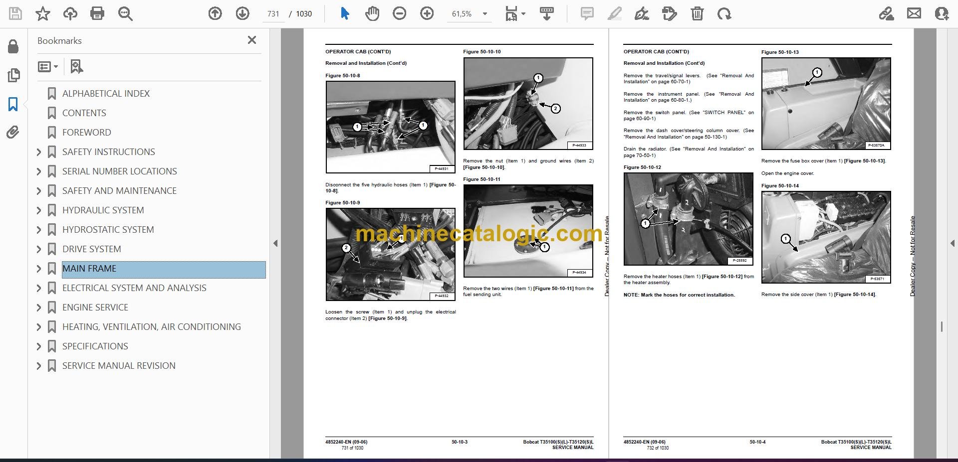
- OPERATOR CAB
- OPERATOR SEAT
- FIXED BOOM
- END BOOM
- WEAR PADS (FRONT)
- WEAR PADS (REAR)
- ENGINE COVER
- Gas Cylinder Removal And Installation
- Removal And Installation
- AIR INTAKE COWLING
- FUEL TANK
- QUICK TACH
- REAR WEIGHTS
- FENDER
- DASH COVER/STEERING COLUMN COVER
- JOYSTICK PANEL
- BOOM TRAY
- INTERMEDIATE BOOM
- CHAIN CHECKING AND ADJUSTING PROCEDURE
- Checking/Adjustment Procedure
- STABILIZER FRAME
- ELECTRICAL SYSTEM AND ANALYSIS
- ELECTRICAL SYSTEM INFORMATION
- Troubleshooting Chart
- Description
- Fuses, Diodes & Relays
- BATTERY
- Removal And Installation
- Servicing
- Using A Booster Battery (Jump Starting)
- ALTERNATOR
- Removal And Installation
- Adjusting The Alternator Belt
- STARTER
- Removal And Installation
- Parts Identification
- Assembly/Disassembly
- LIGHTS
- Rear Light Removal And Installation
- Front Light Removal And Installation
- TRAVEL/SIGNAL LEVER
- INSTRUMENT PANEL
- SWITCH PANEL
- BRAKE LIGHT SWITCH
- Removal And Installation
- Adjustment
- FRONT WIPER MOTOR
- TOP WIPER MOTOR
- REAR WIPER MOTOR
- PEDAL ASSEMBLY
- Removal And Installation
- Disassembly And Assembly
- INCHING SWITCH
- Removal And Installation
- Adjustment
- SERVICE SOFTWARE
- Connecting The Laptop Computer
- Entering The Service Software
- Monitor Screen
- Warnings Screen
- Calibrate Inch Pedal
- FRAME LEVEL SPEED SWITCH
- Description
- Removal
- Installation
- LONGITUDINAL STABILITY INDICATOR CALIBRATION
- Fitting The Sensor
- Calibration Procedure
- ENGINE SERVICE
- TROUBLESHOOTING
- ENGINE SPEED CONTROL
- MUFFLER
- AIR CLEANER
- Housing Removal And Installation
- OIL COOLER/RADIATOR
- Removal And Installation
- Disassembly And Assembly
- ENGINE AND ENGINE MOUNTS
- ENGINE COMPONENTS AND TESTING
- Fuel Injection Pump Removal
- Fuel Injection Pump Installation
- Fuel Injectors Removal And Installation
- Checking The Fuel Lift Pump
- Fuel Lift Pump Removal And Installation
- Compression Checking
- Glow Plugs Checking
- Glow Plugs Removal And Installation
- ENGINE TIMING
- ENGINE/HYDROSTAT ASSEMBLY
- FLYWHEEL AND HOUSING
- RECONDITIONING THE ENGINE
- Turbo Charger Troubleshooting
- Turbo Charger Description
- Turbo Charger Removal And Installation
- Exhaust Manifold Removal And Installation
- Fuel Injector Cover Removal And Installation
- Rocker Cover Removal And Installation
- Cylinder Head Removal
- Cylinder Head Inspection
- Cylinder Head Installation
- Rocker Shaft Disassembly And Assembly
- Valve Removal
- Valve Springs Checking
- Valve Depth Checking
- Valve Guides Checking
- Valve Guide Removal
- Valve Guide Installation
- Valves Checking
- Cutting A Valve Seat
- Valve Seat Assembly
- Changing Valve Springs (With Cylinder Head Installed)
- Valve Clearance Adjustment
- Timing Case And Drive Assembly Description
- Timing Cover Removal
- Timing Cover Installation
- Crankshaft Pulley Removal And Installation
- Timing Case And Gear Removal
- Timing Case And Gear Installation
- Camshaft And Tappets Removal
- Camshaft And Tappets Installation
- Pistons And Connecting Rods Description
- Pistons And Connecting Rods Removal
- Pistons And Connecting Rods Disassembly
- Piston Ring End Gap
- Piston Ring Installation
- Piston Ring Groove Clearance
- Connecting Rod Inspection
- Connecting Rod Bushing Replacement
- Piston And Connecting Rod Assembly
- Piston And Connecting Rod Installation
- Crankshaft And Bearings Description
- Crankshaft And Bearings Removal
- Inspection Of Crankshaft And Bearings
- Crankshaft And Bearings Installation
- Rear Oil Seal Removal
- Rear Oil Seal Installation
- Checking Crankshaft End Play
- Cooling System Description
- Thermostat Removal And Installation
- Thermostat Testing
- Lubricating Oil Cooler Removal And Installation
- Water Pump Removal
- Water Pump Installation
- Engine Lubrication System Description
- Oil Filter Adapter Removal And Installation
- Oil Pan Removal And Installation
- Oil Screen And Pick-up Tube
- Oil Pump Installation
- Oil Pump Disassembly And Assembly
- Oil Pressure Relief Valve Disassembly And Assembly
- Engine Block Description
- Engine Block Disassembly And Assembly
- Piston Cooling Jet Removal
- Piston Cooling Jet Installation
- Piston Cooling Jet Alignment
- Inspection
- Cylinder Liner Inspection
- Cylinder Liner Removal
- Cylinder Liner Installation
- HEATING, VENTILATION, AIR CONDITIONING
- AIR CONDITIONING SYSTEM FLOW
- COMPONENTS
- SAFETY
- REGULAR MAINTENANCE
- Filter Element Removal And Installation
- Compressor Drive Belt Inspection
- Cleaning The Condenser
- BASIC TROUBLESHOOTING
- Poor A/C Performance
- Compressor Drive Belt Inspection
- Checking The Electrical System
- GENERAL AIR CONDITIONING SERVICE GUIDELINES
- Compressor Oil
- Compressor Oil Check
- Component Replacement And Refrigeration Leaks
- SYSTEM TROUBLESHOOTING CHART
- TEMPERATURE/PRESSURE
- AIR CONDITIONING SERVICE
- SYSTEM CHARGING AND RECLAMATION
- Reclamation Procedure
- Charging Procedure With A Manifold Gauge Set
- Charging Procedure
- COMPRESSOR
- Removal And Installation
- Compressor Clutch Disassembly And Assembly
- CONDENSER
- RECEIVER/DRIER
- PRESSURE SWITCH
- EVAPORATOR/BLOWER UNIT
- EXPANSION VALVE
- HEATER ASSEMBLY
- Removal And Installation
- Fan Removal And Installation
- Core Removal And Installation
- SPECIFICATIONS
- Telescopic Handler SPECIFICATIONS
- Dimensional Specifications
- Performance Specificaitons
- Engine
- Controls
- Drive System
- Tires
- Capacities
- Hydraulic System
- Electrical System
- Instrument Panel
- ENGINE SPECIFICATIONS
- General
- Cylinder Head
- Valve Guides
- Exhaust Valves
- Intake Valves
- Valve Springs
- Rocker Shaft, Rockers And Bushings
- Pistons And Piston Rings
- Connecting Rods And Bearings
- Crankshaft
- Crankshaft Re-Grind Data
- Main Bearings
- Thrust Washers
- Camshaft And Thrust Washer
- Cylinder Block
- Cylinder Liners
- Fuel Injection Pump
- Fuel Injectors
- Fuel Lift Pump
- Timing Case And Timing Gears
- Oil Pump, Gear And Relief Valve
- Turbocharger
- Flywheel
- Water Pump And Thermostat
- Engine Torque Component
- MACHINE TORQUE SPECIFICATIONS
- Axle
- Boom
- Drive Box
- Drive Motor
- Engine
- Hydraulic Pump
- TORQUE SPECIFICATIONS FOR BOLTS
- Torque For General SAE Bolts
- Torque For General Metric Bolts
- HYDRAULIC CONNECTION SPECIFICATIONS
- O-ring Face Seal Connection
- Straight Tread O-ring Fitting
- Tubelines And Hoses
- Flare Fitting
- O-ring Flare Fitting
- Port Seal Fitting
- HYDRAULIC/HYDROSTATIC FLUID SPECIFICATIONS
- CONVERSIONS
- Decimal And Millimeter Equivalents
- U.S. To Metric Conversion
- SERVICE MANUAL REVISION
- Revision No: T35100, T35100L, T35100SL, T35120L, T35120SL – 1
Bobcat Software
Bobcat PDF Manuals


