$ 0
0
$ 0
0

Bobcat TL3870 VersaHANDLER® TTC, Telescopic Handler Service Manual (SN AVKJ15000-AVKJ99999)

Format: PDF (Printable Document)

File Language: English

File Pages: 821

File Size: 27.41 MB (Speed Download Link)

Brand: Bobcat

Model: TL3870 VersaHANDLER® TTC, Telescopic Handler

Book No: 7311032

Serial No: SN AVKJ15000-AVKJ99999

Type of Document: Service Manual

Categories: ,

$ 45

Share:

Bobcat TL3870 VersaHANDLER® TTC, Telescopic Handler Service Manual (SN AVKJ15000-AVKJ99999)

On a real job, the TL3870 VersaHANDLER is your telehandler for pallets, hay, and materials where you need reach plus lift, not skid-steer maneuvering. The people who grab this manual are the ones actually turning wrenches: shop mechanics, field techs, and owner-operators trying to keep downtime off the schedule. They're looking for teardown steps, pressure specs, and wiring info so they can fix it right the first time and get it back on rent or back in the field.

What this manual helps you do

  • Diagnose hydraulic issues in the boom, outriggers, and steering using step-by-step checks and pressure test procedures
  • Trace and repair electrical faults with wiring diagrams and connector locations for the TL3870 telehandler
  • Follow teardown and reassembly procedures for major components like the boom sections, axles, and hydraulic cylinders
  • Check and set adjustments on brakes, steering, and hydraulic controls after component replacement
  • Plan and perform scheduled services beyond the basic intervals, with specs that go deeper than the operator's handbook

Who this is for

This is for anyone maintaining or repairing a Bobcat TL3870 VersaHANDLER TTC telehandler in the serial range AVKJ15000 through AVKJ99999. If you only need basic operating instructions or daily checks, you want the operator's handbook instead, not this shop manual.

FAQ

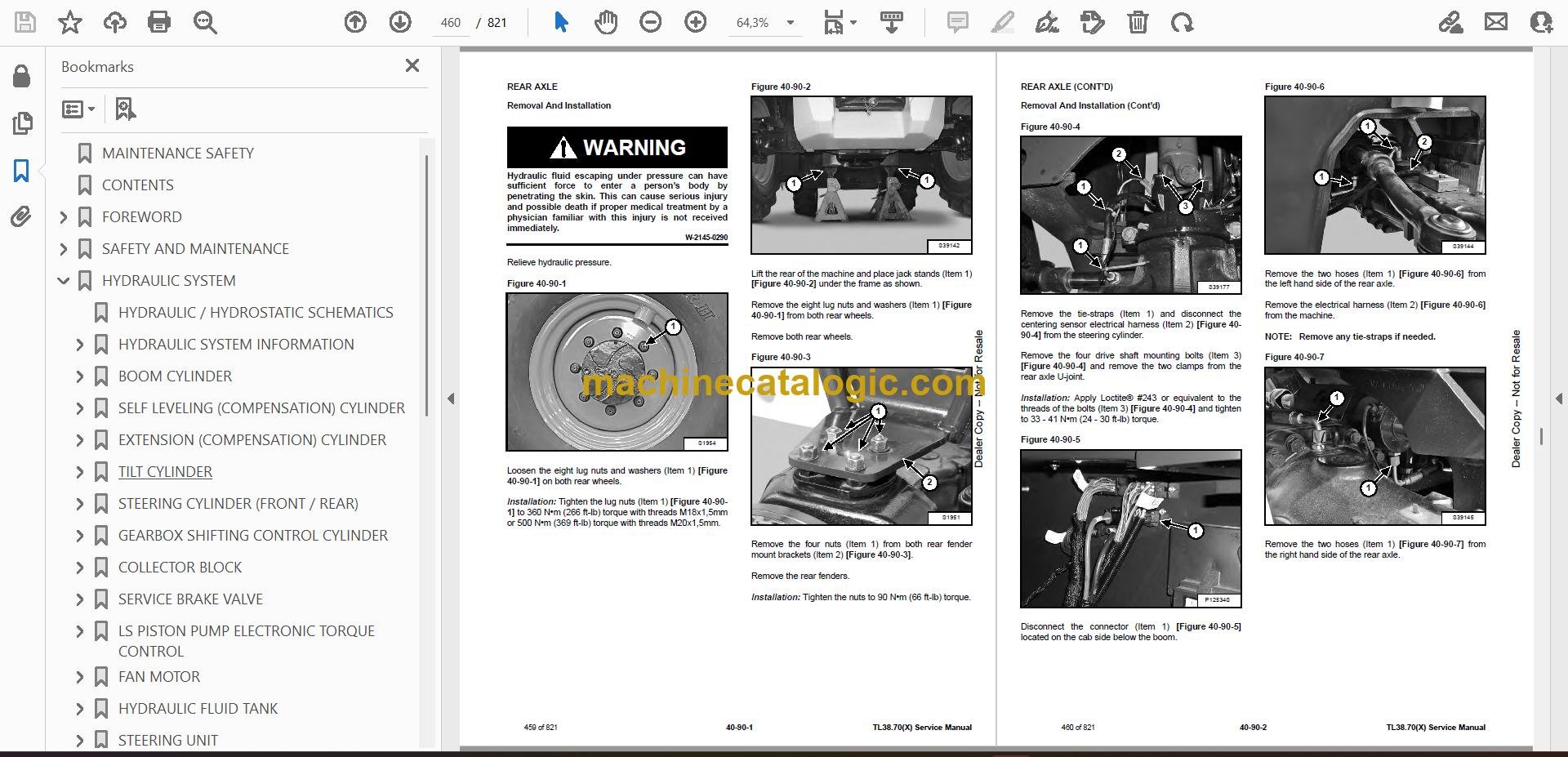
Q: Is this a searchable PDF and are the wiring diagrams readable?

A: Yes, these manuals are normally delivered as searchable PDF files, and the wiring diagrams are laid out so you can zoom in and read pin labels and wire colors.

Q: How do I know if it covers my exact machine?

A: If your TL3870 serial number falls between AVKJ15000 and AVKJ99999, this is the right service manual for your machine variant.

Q: Is this the right document if I'm doing major repairs?

A: Yes, this is the workshop-level service manual, meant for diagnostics, teardown, and major repairs, not just routine greasing and fluid checks.

Bottom line: If you own or service a TL3870 in that serial range and you're doing real repairs, this is the manual you want. If you just need how to run it, skip this and get the operator's book.

📘 Show Index

Table of Contents:

  • MAINTENANCE SAFETY
  • CONTENTS
  • FOREWORD
    • FOREWORD
    • SAFETY INSTRUCTIONS
      • Safe Operation Is The Operator’s Responsibility
      • Safe Operation Needs A Qualified Operator
      • Avoid Silica Dust
      • Dismantling And Disposal
    • FIRE PREVENTION
      • Maintenance
      • Operation
      • Electrical
      • Hydraulic System
      • Fueling
      • Starting
      • Welding And Grinding
      • Fire Extinguishers
    • PUBLICATIONS AND TRAINING RESOURCES
    • SERIAL NUMBER LOCATION
      • Telescopic Handler Serial Number
      • Engine Serial Number
      • Other Serial Numbers
    • DELIVERY REPORT
    • BOBCAT TELESCOPIC HANDLER IDENTIFICATION
  • SAFETY AND MAINTENANCE
    • LIFTING AND BLOCKING THE TELESCOPIC HANDLER
      • Procedure
    • OPERATOR CAB
      • Description
      • Cab Door
      • Cab Door Window
      • Rear Cab Window
      • Cab Light
    • TRANSPORTING THE TELESCOPIC HANDLER ON A TRAILER
      • Loading And Unloading
      • Fastening
    • TOWING THE TELESCOPIC HANDLER
      • Procedure
    • SERVICE SCHEDULE
      • Maintenance Intervals
    • AIR CLEANER SERVICE
      • Replacing Filter Elements
    • COOLING SYSTEM
      • Cleaning
      • Checking Level
      • Removing And Replacing The Coolant
    • FUEL SYSTEM
      • Fuel Specifications
      • Biodiesel Blend Fuel
      • Filling The Fuel Tank
      • Primary Fuel Filter (Pre-Filter)
      • Secondary Fuel Filters
      • Removing Air From The Fuel System
    • ENGINE LUBRICATION SYSTEM
      • Checking And Adding Engine Oil
      • Engine Oil Chart
      • Removing And Replacing Oil And Filter
    • HYDRAULIC / HYDROSTATIC SYSTEM
      • Checking And Adding Fluid
      • Removing And Replacing Hydraulic Fluid
      • Removing And Replacing Hydraulic / Hydrostatic Filters
      • Removing And Replacing Hydraulic Charge Filter
      • Fill / Breather Cap
      • Hydraulic Fluid Air Bleeding Procedure
      • Starter Procedure
    • AXLES (FRONT AND REAR)
      • Checking And Adding Oil (Planetary Carrier)
      • Removing And Replacing Oil (Planetary Carrier)
      • Checking And Adding Oil (Rear Differential)
      • Removing And Replacing Oil (Rear Differential)
      • Checking And Adding Oil (Front Differential)
      • Removing And Replacing Oil (Front Differential)
      • Checking And Adding Oil (Gearbox)
      • Removing And Replacing Oil (Gearbox)
    • LUBRICATING THE TELESCOPIC HANDLER
      • Lubrication Locations
      • Front Pads Lubrication
      • Rear Pads Lubrication
    • ATTACHMENT CARRIER
      • Inspection And Maintenance
    • TIRE MAINTENANCE
      • Wheel Nuts
      • Rotating
      • Mounting
      • Pressure
      • Wheel Replacement
    • APPROVED BOOM STOP
      • Installing The Approved Boom Stop
      • Removing The Approved Boom Stop
    • ENGINE COVER
      • Opening And Closing
    • STOPPING THE ENGINE AND LEAVING THE TELESCOPIC HANDLER
      • Procedure
    • EMERGENCY EXIT
      • Rear Window
    • TELESCOPIC HANDLER STORAGE AND RETURN TO SERVICE
      • Storage
      • Return To Service
    • LIFTING THE TELESCOPIC HANDLER
      • Procedure
    • REMOTE START TOOL (SERVICE TOOL) KIT – 6987761
      • Remote Start Tool (Service Tool) – 7022042
      • Telescopic Handler Service Tool Harness – 6689747
      • Computer Service Tool Harness – 6689746
      • Remote Start Procedure
  • HYDRAULIC SYSTEM
    • HYDRAULIC / HYDROSTATIC SCHEMATICS
    • HYDRAULIC SYSTEM INFORMATION
      • Glossary Of Hydraulic / Hydrostatic Symbols
      • Troubleshooting Chart
      • Tightening Procedures
    • BOOM CYLINDER
      • Removal And Installation
      • Parts Identification
      • Disassembly
      • Assembly
    • SELF LEVELING (COMPENSATION) CYLINDER
      • Removal And Installation
      • Parts Identification
      • Disassembly
      • Assembly
    • EXTENSION (COMPENSATION) CYLINDER
      • Cylinder Group Removal And Installation
      • Upper Tubeline Removal And Installation
      • Extension Cylinder Removal And Installation
      • Tubeline Tray Disassembly
      • Parts Identification
      • Disassembly
      • Assembly
    • TILT CYLINDER
      • Removal And Installation
      • Parts Identification
      • Disassembly
      • Assembly
    • STEERING CYLINDER (FRONT / REAR)
      • Removal
      • Installation
      • Disassembly
      • Assembly
    • GEARBOX SHIFTING CONTROL CYLINDER
      • Removal
      • Parts Identification
      • Disassembly
      • Assembly
      • Installation
    • COLLECTOR BLOCK
      • Removal And Installation
      • Parts Identification
      • Disassembly And Assembly
    • SERVICE BRAKE VALVE
      • Removal And Installation
    • LS PISTON PUMP ELECTRONIC TORQUE CONTROL
      • LS Piston Pump Testing
      • Cycle Times @ Full Idle
      • Troubleshooting Chart (LS Piston Pump Testing)
      • Removal And Installation
      • Parts Identification
      • Disassembly And Assembly
    • FAN MOTOR
      • Description
      • Removal And Installation
      • Parts Identification (Single Speed Version) (Standard)
      • Disassembly And Assembly (Single Speed Version) (Standard)
      • Parts Identification (Variable Speed Version)
      • Disassembly And Assembly (Variable Speed Version)
    • HYDRAULIC FLUID TANK
      • Removal And Installation
    • STEERING UNIT
      • Removal And Installation
    • MAIN VALVE
      • Troubleshooting Chart (Controllers)
      • Valve Section Troubleshooting
      • Troubleshooting Chart (Main Valve)
      • Main Relief Valve Removal And Installation
      • Removal And Installation
      • Parts Identification
      • Disassembly And Assembly
      • End Housing Disassembly And Assembly
      • Auxiliary Valve Section Disassembly And Assembly
      • Telescoping Valve Section Disassembly And Assembly
      • Tilting Valve Section Disassembly And Assembly
      • Lifting Valve Section Disassembly And Assembly
      • Inlet-Outlet Valve Section Disassembly And Assembly
    • PORT RELIEF VALVES
      • Testing
      • Replacement Procedure
    • ACCUMULATORS
      • Accumulators Pressure Relief
      • LS Pump Accumulator Removal And Installation
      • Power Lift Accumulator Removal And Installation
    • FAN PUMP
      • Removal And Installation
      • Disassembly And Assembly
    • POWER LIFT SYSTEM
      • Description
      • Removing And Installing The Pressure Reducer Valve
      • Removing And Installing The Counterbalance Valve
    • TRAILER BRAKE VALVE
      • Description
      • Removal And Installation
    • BOOM SUSPENSION AND FLOAT SYSTEM
      • Boom Suspension Functional Description
      • Boom Float Functional Description
      • Removing And Installing The Boom Suspension Valve
  • HYDROSTATIC SYSTEM
    • HYDROSTATIC SYSTEM INFORMATION
      • Troubleshooting Chart
      • Replenishing Valve Function
      • Test Coupler Location
    • OIL COOLER
      • Description
    • HYDROSTATIC DRIVE MOTOR
      • Removal And Installation
      • Parts Identification
      • Disassembly
      • Inspection
      • Assembly
    • HYDROSTATIC PUMP
      • Removal And Installation
      • Parts Identification
      • Shaft Disassembly
      • Relief Valves Disassembly And Assembly
      • Charge Pump Disassembly
      • Piston Pump Disassembly
      • Solenoid Block Disassembly
      • Inspection
      • Piston Pump Assembly
      • Charge Pump Assembly
      • Solenoid Block Assembly
      • Shaft Assembly
    • CHARGE PRESSURE
      • Description
      • Testing And Adjusting
    • MULTIFUNCTION VALVES
      • Description
      • Testing
  • DRIVE SYSTEM
    • TROUBLESHOOTING
      • Chart
    • AXLE AND DIFFERENTIAL (FRONT)
      • Description
      • Planetary Carrier And Drive Axle Parts Identification
      • Planetary Carrier Disassembly
      • Steering Knuckle Parts Identification
      • Steering Knuckle Disassembly
      • Drive Axle Disassembly
      • Brake Group Parts Identification
      • Brake Group Disassembly
      • Differential And Pinion Group Parts Identification
      • Differential Disassembly
      • Pinion Group Disassembly
      • Pinion Group Assembly
      • Differential Assembly
      • Brake Group Assembly
      • Drive Axle Assembly
      • Steering Knuckle Assembly
      • Planetary Carrier Assembly
    • AXLE AND DIFFERENTIAL (REAR)
      • Description
      • Planetary Carrier And Drive Axle Parts Identification
      • Planetary Carrier Disassembly
      • Steering Knuckle Parts Identification
      • Steering Knuckle Disassembly
      • Differential And Pinion Group Parts Identification
      • Differential Disassembly
      • Pinion Group Disassembly
      • Pinion Group Assembly
      • Differential Assembly
      • Steering Knuckle Assembly
      • Planetary Carrier Assembly
    • FRONT AXLE
      • Removal And Installation
    • AXLE TOE-IN
      • Adjustment
    • PARK BRAKE
      • Releasing The Brake For Towing
      • Adjustment
      • Brake Cylinder Removal
      • Brake Cylinder Disassembly And Assembly
      • Brake Disc Removal And Installation
      • Brake Cylinder Installation
    • STEERING ANGLE ADJUSTMENT
      • Adjustment
    • DRIVESHAFT
      • Rear Driveshaft Removal And Installation
      • Front Driveshaft Removal And Installation
    • SERVICE BRAKE
      • Description
      • Bleeding The Brake Circuit
    • REAR AXLE
      • Removal And Installation
    • GEARBOX
      • Removal And Installation
      • Parts Identification
      • Disassembly
      • Assembly
  • MAINFRAME
    • OPERATOR CAB
      • Removal And Installation
    • OPERATOR SEAT
      • Removal And Installation
    • FIXED BOOM
      • Removal
      • Installation
    • INNER BOOM
      • Removal And Installation
    • WEAR PADS (FRONT)
      • Boom Wear Pad Checking
      • Removal And Installation
    • WEAR PADS (REAR)
      • Boom Wear Pad Checking
      • Removal And Installation
    • ENGINE COVER
      • Gas Cylinder Removal And Installation
      • Removal And Installation
    • FUEL TANK
      • Removal And Installation
    • ATTACHMENT CARRIER (QUICK-TACH)
      • Removal And Installation
    • COUNTERWEIGHT
      • Removal And Installation
    • FENDER
      • Removal And Installation
    • STEERING COLUMN COVER
      • Removal And Installation
    • DASH COVER
      • Removal And Installation
    • JOYSTICK PANEL
      • Removal And Installation
  • ELECTRICAL SYSTEM AND ANALYSIS
    • ELECTRICAL SCHEMATICS
    • ELECTRICAL SYSTEM INFORMATION
      • Glossary Of Electrical Symbols
      • Cab Harness Connectors
      • Mainframe Harness Connectors
      • Engine Bay Harness Connectors
      • Troubleshooting Chart
      • Description
      • Fuses And Relay Location / Identification
    • BATTERY
      • Battery Maintenance
      • Using A Booster Battery (Jump Starting)
      • Removing And Installing Battery
    • ALTERNATOR
      • Inspection
      • Removal And Installation
      • Belt Adjustment
      • Belt Checking
      • Belt Replacement
    • STARTER
      • Testing
      • Removal And Installation
    • LIGHTS
      • Rear Light Removal And Installation
      • Front Light Removal And Installation
      • Rear Work Light Removal And Installation
    • SIGNAL LEVER
      • Removal And Installation
    • DISPLAY
      • Removal And Installation
    • INSTRUMENT PANELS
      • Right Instrument And Indicator Panel Removal And Installation
      • Left Instrument Panel Removal And Installation
    • BOOM ANGLE SENSOR
      • Description
      • Removal And Installation
    • FRONT WIPER MOTOR
      • Removal And Installation
    • TOP WIPER MOTOR
      • Removal And Installation
    • REAR WIPER MOTOR
      • Removal And Installation
    • SERVICE BRAKE PEDAL ASSEMBLY
      • Removal And Installation
    • INCHING SENSOR
      • Description
      • Removal And Installation
      • Calibration
    • EMERGENCY BRAKE
      • Description
    • SERVICE PC (LAPTOP COMPUTER)
      • Connecting Remote Start Tool (Service Tool) – 6987761
    • FUEL LEVEL SENDER
      • Removal And Installation
    • JOYSTICK
      • Removal And Installation
    • LLMI / LLMC SYSTEM
      • System Components Identification
      • Longitudinal Load Moment Indicator (LLMI) Description
      • Longitudinal Load Moment Controller (LLMC)
      • Longitudinal Load Moment Controller (LLMC) Override Switch
      • LLMS Removal
      • LLMS Installation
    • MAINTENANCE CLOCK
      • Description
      • Setup
      • Reset
    • CONTROLLERS
      • Description
      • Gateway Controller
      • Drive Controller
      • Workgroup Controller
      • Display Controller
      • LLMI Controller
      • LLMC Controller
      • Engine Controller
    • RETRACT SENSOR
      • Removal And Installation
      • Adjustment
    • AUTOMATIC PARK BRAKE
      • Description
    • CALIBRATION
      • Calibrating The Hydrostatic Pump
      • Calibrating The Boom Angle Sensor
      • Calibrating The Inching Sensor
      • Calibrating The LLMC System
      • LLMC Calibration Test
      • LLMI / LLMC System Failure Reports
  • ENGINE SERVICE
    • ENGINE
      • Fuel System Information
      • Specifications
      • Troubleshooting
      • Removal And Installation
    • ENGINE BAY ASSEMBLY
      • Removal And Installation
    • ENGINE SPEED CONTROL
      • Removal And Installation
    • MUFFLER
      • Removal And Installation
    • AIR CLEANER
      • Housing Removal And Installation
    • COOLING SYSTEM
      • Hydraulic Oil Cooler / Intercooler / Radiator Removal And Installation
      • Water Temperature Regulator Removal
      • Water Temperature Regulator Installation
      • Water Temperature Regulator Test
      • Cooling System Check
      • Cooling System Inspection
      • Engine Oil Cooler Removal
      • Engine Oil Cooler Installation
      • Engine Oil Cooler Inspection
      • Water Pump Removal
      • Water Pump Installation
      • Water Pump Inspection
      • Water Pump Bypass Tube Removal
      • Water Pump Bypass Tube Installation
      • Expansion Tank Removal And Installation
    • LUBRICATION SYSTEM
      • Engine Oil Filter Base Removal
      • Engine Oil Filter Base Installation
      • Engine Oil Pressure Test
      • Excessive Engine Oil Consumption Inspection
      • Increased Engine Oil Temperature Inspection
      • Excessive Bearing Wear Inspection
    • FUEL SYSTEM
      • Fuel Priming Pump Removal
      • Fuel Priming Pump Installation
      • Fuel System Inspection
      • Fuel Quality Test
      • Fuel System Prime
    • CYLINDER HEAD
      • Valve Mechanism Cover Removal
      • Valve Mechanism Cover Installation
      • Air Inlet And Exhaust System Inspection
      • Valve Clearance Adjustment
    • CRANKSHAFT SEALS AND BEARINGS
      • Crankshaft Rear Seal Removal
      • Crankshaft Rear Seal Installation
      • Crankshaft Wear Sleeve (Rear) Removal
      • Crankshaft Wear Sleeve (Rear) Installation
      • Crankshaft Front Seal Removal
      • Crankshaft Front Seal Installation
      • Crankshaft Wear Sleeve (Front) Removal
      • Crankshaft Wear Sleeve (Front) Installation
    • TIMING COVER
      • Timing Cover Removal
      • Timing Cover Installation
    • CRANKSHAFT PULLEY
      • Crankshaft Pulley Removal
      • Crankshaft Pulley Installation
      • Crankshaft Pulley Check
    • TURBOCHARGER
      • Troubleshooting
      • Description
      • Removal And Installation
    • FLYWHEEL AND HOUSING
      • Flywheel Removal
      • Flywheel Installation
      • Flywheel Inspection
      • Flywheel Housing Removal
      • Flywheel Housing Installation
      • Flywheel Housing Inspection
      • Crankcase Breather Removal
      • Crankcase Breather Installation
    • ENGINE CONTROL UNIT (ECU)
      • Removing The Engine Control Unit (ECU)
      • Installing The Engine Control Unit (ECU)
      • Removing The Mounting Bracket
      • Installing The Mounting Bracket
  • HEATING, VENTILATION, AIR CONDITIONING (HVAC)
    • AIR CONDITIONING SYSTEM FLOW
      • Description
      • Chart
      • Components
      • Safety Equipment
    • REGULAR MAINTENANCE
      • Filters
      • Air Conditioning Belt Adjustment
      • Belt Replacement
      • Cleaning The Condenser
      • Air Conditioning Lubrication
      • Air Conditioning Service Chart
      • Evaporator / Heater Coil
    • TROUBLESHOOTING
      • Blower Motor Does Not Operate
      • Blower Motor Operates Normally, But Air Flow Is Insufficient
      • Insufficient Cooling Although Air Flow And Compressor Operation Are Normal
      • The Compressor Does Not Operate At All, Or Operates Improperly
      • Gauge Pressure Related Troubleshooting
      • Temperature / Pressure Chart
      • Poor A/C Performance
      • HVAC Repair And Leaks
      • Electrical System
    • SYSTEM CHARGING AND RECLAMATION
      • Reclamation And Charging With Recovery / Charging Unit
    • COMPRESSOR
      • Removal And Installation
      • Oil
      • Oil Check
      • Clutch Disassembly And Assembly
    • CONDENSER
      • Removal And Installation
    • RECEIVER / DRIER
      • Removal And Installation
    • PRESSURE SWITCH
      • Removal And Installation
    • EVAPORATOR / HEATER UNIT
      • Removal And Installation
    • THERMOSTAT
      • Description
      • Removal And Installation
    • EXPANSION VALVE
      • Removal And Installation
  • SPECIFICATIONS
    • (TL38.70(X)) TELESCOPIC HANDLER SPECIFICATIONS
      • Machine Dimensions
      • Performance
      • Weights
      • Engine
      • Controls
      • Drive System
      • Traction
      • Steering
      • Brakes
      • Fluid Capacities
      • Hydraulic System
      • Electrical System
      • Temperature Range
      • Altitude
      • Instrument Panel
      • Environmental
    • LIFTING AND TIE-DOWN SPECIFICATIONS
      • Lifting
      • Tie Down
    • MACHINE TORQUE SPECIFICATIONS
      • Axle
      • Boom
      • Drive Box
      • Drive Motor
      • Engine
      • Hydraulic Pump
    • TORQUE SPECIFICATIONS FOR BOLTS
      • Torque for General SAE Bolts
      • Torque For General Metric Bolts
    • HYDRAULIC CONNECTION SPECIFICATIONS
      • O-ring Face Seal Connection
      • Straight Thread O-ring Fitting
      • Tubelines And Hoses
      • Flare Fitting
      • O-ring Flare Fitting
      • Port Seal Fitting
    • HYDRAULIC / HYDROSTATIC FLUID SPECIFICATIONS
      • Specifications
    • CONVERSIONS
      • Decimal And Millimeter Equivalent Chart
      • U.S. To Metric Conversion Chart
    • SERVICE TOOLS REQUIRED
      • Remote Start Tools
      • Hydraulic Tools
      • Drive Tools
      • Electrical Tools
      • Engine Tools
      • Special Drive Tools
  • ALPHABETICAL INDEX

Bobcat Software

Bobcat PDF Manuals

Related Manuals

0
    0
    Your Cart
    Your cart is emptyReturn to Shop