$ 0
0
$ 0
0

Bobcat T35130 VersaHANDLER® TTC, Telescopic Handler Service Manual (SN B51411001-B51499999)

Format: PDF (Printable Document)

File Language: English

File Pages: 822

File Size: 28.12 MB (Speed Download Link)

Brand: Bobcat

Model: T35130 VersaHANDLER® TTC, Telescopic Handler

Book No: 7400386

Serial No: SN B51411001-B51499999

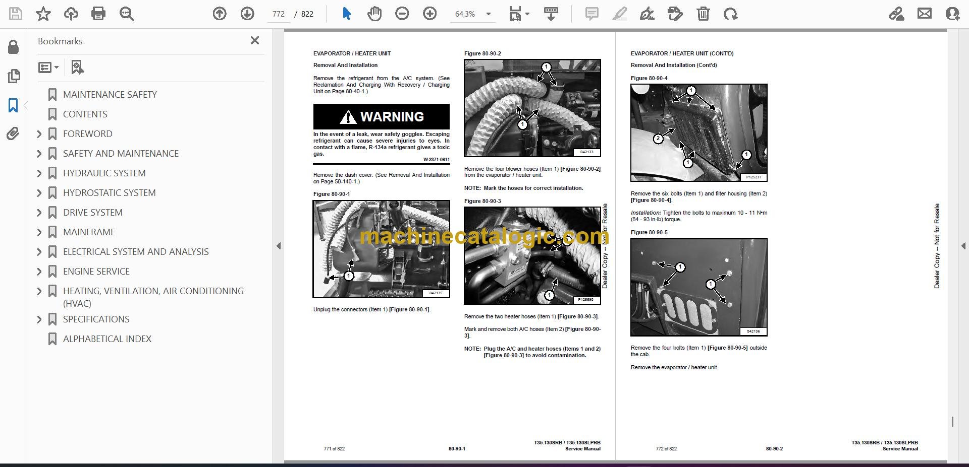
Type of Document: Service Manual

Categories: ,

$ 45

Share:

Bobcat T35130 VersaHANDLER® TTC, Telescopic Handler Service Manual (SN B51411001-B51499999)

On a real job, a T35130 VersaHANDLER TTC is your forklift-on-steroids for truss work, pallet handling, and farm or yard loading where you need reach and height. The people who grab this service manual are the ones actually keeping it moving: shop mechanics, field techs, and owner-operators who turn their own wrenches. They're looking for correct teardown order, hydraulic pressures, wiring logic, and how to get the boom and stabilizers working right again without guesswork.

What this manual helps you do

  • Diagnose boom, outrigger, and steering hydraulic issues, then check pressures and chase internal leaks
  • Trace and repair electrical faults in the control system, safety interlocks, and lighting using wiring diagrams
  • Follow step-by-step procedures to remove, disassemble, and rebuild major components like the boom sections, cylinders, and drive components
  • Adjust and verify limit switches, load handling controls, and safety systems after repairs
  • Replace wear parts on a schedule, set clearances, and confirm everything with spec checks during 50/250/500-hour services

Who this is for

This manual is for anyone maintaining or repairing a Bobcat T35130 VersaHANDLER TTC telescopic handler in the serial range B51411001 to B51499999, whether you're a small contractor, rental fleet, or farm shop. If you just need basic operating instructions or daily checks, you want the operator's handbook instead.

FAQ

Q: Is this a searchable PDF and are the wiring diagrams readable?

A: These manuals are usually supplied as searchable PDFs, and the wiring diagrams are laid out so you can zoom in and read pin numbers and wire colors.

Q: How do I know if it matches my machine?

A: Check your serial plate. If your T35130 VersaHANDLER TTC falls in the B51411001-B51499999 range, this is the right book.

Q: Is this the right manual if I only need parts numbers?

A: No, for part numbers you need the parts catalog. This is the repair and diagnostic manual.

Bottom line: If you're actually fixing or maintaining a T35130 in that serial range, this is the yes you're looking for. If you're just learning to run it, skip this one.

📘 Show Index

Table of Contents:

  • MAINTENANCE SAFETY
  • CONTENTS
  • FOREWORD
    • FOREWORD
    • SAFETY INSTRUCTIONS
      • Safe Operation Is The Operator’s Responsibility
      • Safe Operation Needs A Qualified Operator
      • Avoid Silica Dust
      • Dismantling And Disposal
    • FIRE PREVENTION
      • Maintenance
      • Operation
      • Electrical
      • Hydraulic System
      • Fueling
      • Starting
      • Welding And Grinding
      • Fire Extinguishers
    • PUBLICATIONS AND TRAINING RESOURCES
    • SERIAL NUMBER LOCATION
      • Telescopic Handler Serial Number
      • Engine Serial Number
      • Other Serial Numbers
    • DELIVERY REPORT
    • BOBCAT TELESCOPIC HANDLER IDENTIFICATION
  • SAFETY AND MAINTENANCE
    • LIFTING AND BLOCKING THE TELESCOPIC HANDLER
      • Procedure
    • OPERATOR CAB
      • Description
      • Cab Door
      • Cab Door Window
      • Rear Cab Window
      • Cab Light
    • TRANSPORTING THE TELESCOPIC HANDLER ON A TRAILER
      • Loading And Unloading
      • Fastening
    • TOWING THE TELESCOPIC HANDLER
      • Procedure
    • SERVICE SCHEDULE
      • Maintenance Intervals
    • AIR CLEANER SERVICE
      • Replacing Filter Elements
      • Cleaning The Dust Extractor
    • COOLING SYSTEM
      • Cleaning
      • Checking Level
      • Removing And Replacing The Coolant
    • FUEL SYSTEM
      • Fuel Specifications
      • Filling The Fuel Tank
      • Replacing The Fuel Tank Breather
      • Fuel Pre-Filter
      • Fuel Filter
      • Removing Air From The Fuel System
    • ENGINE LUBRICATION SYSTEM
      • Checking And Adding Engine Oil
      • Engine Oil Chart
      • Removing And Replacing Oil And Filter
    • HYDRAULIC / HYDROSTATIC SYSTEM
      • Checking And Adding Fluid
      • Removing And Replacing Hydraulic Fluid
      • Removing And Replacing Hydraulic / Hydrostatic Filters
      • Fill / Breather Cap
    • AXLES (FRONT AND REAR)
      • Checking And Adding Oil (Planetary Carrier)
      • Removing And Replacing Oil (Planetary Carrier)
      • Checking And Adding Oil (Rear Differential)
      • Removing And Replacing Oil (Rear Differential)
      • Checking And Adding Oil (Front Differential)
      • Removing And Replacing Oil (Front Differential)
      • Checking And Adding Oil (Reduction Box)
      • Removing And Replacing Oil (Reduction Box)
    • LUBRICATING THE TELESCOPIC HANDLER
      • Lubrication Locations
      • Front Pads Lubrication
      • Rear Pads Lubrication
    • ATTACHMENT CARRIER
      • Inspection And Maintenance
    • TIRE MAINTENANCE
      • Wheel Nuts
      • Rotating
      • Wheel Replacement
      • Mounting
      • Pressure
    • APPROVED BOOM STOP
      • Installing The Approved Boom Stop
      • Removing The Approved Boom Stop
    • ENGINE COVER
      • Opening And Closing
    • CHAIN CHECKING AND ADJUSTING PROCEDURE
      • Checking / Adjustment Procedure
      • Extension / Retraction Chain Wear Check
    • STOPPING THE ENGINE AND LEAVING THE TELESCOPIC HANDLER
      • Procedure
    • EMERGENCY EXIT
      • Rear Window
    • TELESCOPIC HANDLER STORAGE AND RETURN TO SERVICE
      • Storage
      • Return To Service
    • LIFTING THE TELESCOPIC HANDLER
      • Procedure
    • REMOTE START TOOL (SERVICE TOOL) KIT – 6987761
      • Remote Start Tool (Service Tool) – 7022042
      • Telescopic Handler Service Tool Harness – 6689747
      • Computer Service Tool Harness – 6689746
      • Remote Start Procedure
  • HYDRAULIC SYSTEM
    • HYDRAULIC / HYDROSTATIC SCHEMATICS
    • HYDRAULIC SYSTEM INFORMATION
      • Glossary Of Hydraulic / Hydrostatic Symbols
      • Troubleshooting Chart
      • Tightening Procedures
      • Test Coupler Location
    • BOOM CYLINDER
      • Removal And Installation
      • Parts Identification
      • Disassembly
      • Assembly
    • SELF LEVELING (COMPENSATION) CYLINDER
      • Removal And Installation
      • Parts Identification
      • Disassembly
      • Assembly
    • EXTENSION CYLINDER
      • Cylinder Group Removal And Installation
      • Parts Identification
      • Disassembly
      • Assembly
    • TILT CYLINDER
      • Removal And Installation
      • Parts Identification
      • Disassembly
      • Assembly
    • STEERING CYLINDER (FRONT / REAR)
      • Removal
      • Installation
      • Disassembly
      • Assembly
    • BRAKES BLOCK
      • Removing And Installing The Standard Brakes Block
      • Removing And Installing The Italian Brakes Block
      • Removing And Installing The German Brakes Block
    • ACCUMULATORS
      • Accumulators Pressure Relief
      • Removing And Installing The Park / Service Brake Accumulator
      • Removing And Installing The Boom Lift Valve Accumulator
    • SERVICE BRAKE VALVE
      • Removal And Installation
    • TANDEM GEAR PUMP
      • Removal And Installation
      • Parts Identification
      • Disassembly And Assembly
    • TANDEM GEAR PUMP (TESTING)
      • Fan Gear Pump Direct Test
      • Steering And Valve Gear Pump Direct Test
    • FAN MOTOR
      • Description
      • Removal And Installation
      • Parts Identification (Single Speed Version) (Standard)
      • Disassembly And Assembly (Single Speed Version) (Standard)
      • Parts Identification (Variable Speed Version) (Optional)
      • Disassembly And Assembly (Variable Speed Version) (Optional)
    • FAN MOTOR (VARIABLE SPEED FAN MOTOR TESTING)
      • Description
      • Testing
    • HYDRAULIC FLUID TANK
      • Removal And Installation
    • STEERING UNIT
      • Removal And Installation
    • STEERING UNIT (TESTING)
      • Testing The Steering Unit Main Relief Valve
    • MAIN VALVE
      • Troubleshooting Chart (Solenoid Valves)
      • Valve Section Troubleshooting
      • Troubleshooting Chart (Main Valve)
      • Removal And Installation
      • Section Removal
      • Section Disassembly And Assembly
      • Inlet-Outlet Valve Section Disassembly And Assembly
      • End Housing Disassembly And Assembly
    • MAIN RELIEF VALVE
      • Testing
      • Adjusting
    • PORT RELIEF VALVES
      • Removal And Installation
    • DIVERTER VALVE
      • Removal And Installation
    • SELF LEVELING VALVE
      • Removal And Installation
    • AUXILIARY HYDRAULIC FLOW
      • Testing The Auxiliary Hydraulic Flow
    • STABILIZER / FRAME LEVELING VALVE
      • Removal
      • Installation
      • Disassembly
      • Solenoid Testing
      • Assembly
    • STABILIZER CYLINDER
      • Removal
      • Parts Identification
      • Disassembly
      • Assembly
      • Installation
    • FRAME LEVELING CYLINDER
      • Removal And Installation
      • Parts Identification
      • Disassembly
      • Assembly
  • HYDROSTATIC SYSTEM
    • HYDROSTATIC SYSTEM INFORMATION
      • Troubleshooting Chart
      • Test Coupler Location
    • OIL COOLER
      • Description
    • HYDROSTATIC DRIVE MOTOR
      • Removal And Installation
      • Parts Identification
      • Disassembly
      • Inspection
      • Assembly
    • HYDROSTATIC PUMP
      • Removal And Installation
      • Parts Identification
      • Shaft Disassembly
      • Relief Valves Disassembly And Assembly
      • Charge Pump Disassembly
      • Piston Pump Disassembly
      • Solenoid Block Disassembly
      • Inspection
      • Piston Pump Assembly
      • Charge Pump Assembly
      • Solenoid Block Assembly
      • Shaft Assembly
    • CHARGE PRESSURE
      • Description
      • Testing And Adjusting
    • MULTI-FUNCTION VALVES
      • Description
      • Testing
    • PRESSURE COMPENSATION OVERRIDE VALVE (PCOR)
      • Description
      • Testing And Adjusting
  • DRIVE SYSTEM
    • DRIVE SYSTEM TROUBLESHOOTING
      • Chart
    • AXLE AND DIFFERENTIAL (FRONT)
      • Description
      • Planetary Carrier And Drive Axle Parts Identification
      • Planetary Carrier Disassembly
      • Steering Knuckle Parts Identification
      • Steering Knuckle Disassembly
      • Drive Axle Disassembly
      • Brake Group Parts Identification
      • Brake Group Disassembly
      • Differential And Pinion Group Parts Identification
      • Differential Disassembly
      • Pinion Group Disassembly
      • Pinion Group Assembly
      • Differential Assembly
      • Brake Group Assembly
      • Drive Axle Assembly
      • Steering Knuckle Assembly
      • Planetary Carrier Assembly
    • AXLE AND DIFFERENTIAL (REAR)
      • Description
      • Planetary Carrier And Drive Axle Parts Identification
      • Planetary Carrier Disassembly
      • Steering Knuckle Parts Identification
      • Steering Knuckle Disassembly
      • Differential And Pinion Group Parts Identification
      • Differential Disassembly
      • Pinion Group Disassembly
      • Pinion Group Assembly
      • Differential Assembly
      • Steering Knuckle Assembly
      • Planetary Carrier Assembly
    • FRONT AXLE
      • Removal
      • Installation
      • Mounting Bolts Tightening Torque Check
    • AXLE TOE-IN
      • Adjustment
    • STEERING ANGLE ADJUSTMENT
      • Adjustment
    • PARKING BRAKE
      • Parking Brake Removal, Disassembly And Assembly
    • REDUCTION BOX
      • Removal And Installation
      • Parts Identification
      • Disassembly
      • Assembly
    • DRIVE SHAFT
      • Removal And Installation
    • SERVICE BRAKE
      • Description
      • Bleeding The Brake Circuit
    • REAR AXLE
      • Removal And Installation
  • MAINFRAME
    • OPERATOR CAB
      • Removal And Installation
    • OPERATOR SEAT
      • Removal And Installation
    • BOOM ASSEMBLY
      • Removal And Installation
    • BOOM TRAY
      • Removal And Installation
    • END BOOM
      • Removal
      • Installation
    • INTERMEDIATE BOOM
      • Removal
      • Installation
    • WEAR PADS (FRONT)
      • Boom Wear Pad Checking
      • Removal
      • Installation
    • WEAR PADS (REAR)
      • Boom Wear Pad Checking
      • Removal
      • Installation
    • ENGINE COVER
      • Gas Cylinder Removal And Installation
      • Removal And Installation
    • FUEL TANK
      • Removal And Installation
    • ATTACHMENT CARRIER (QUICK-TACH)
      • Removal And Installation
    • COUNTERWEIGHT
      • Removal And Installation
    • FENDER
      • Removal And Installation
    • STEERING COLUMN COVER
      • Removal And Installation
    • DASH COVER
      • Removal And Installation
    • JOYSTICK PANEL
      • Removal And Installation
    • STABILIZER FRAME
      • Removal
  • ELECTRICAL SYSTEM AND ANALYSIS
    • ELECTRICAL SCHEMATICS
    • ELECTRICAL SYSTEM INFORMATION
      • Glossary Of Electrical Symbols
      • Cab Harness Connectors
      • Mainframe Harness Connectors
      • Engine Bay Harness Connectors
      • Engine Harness Connectors
      • Troubleshooting Chart
      • Description
      • Fuses And Relay Location / Identification
    • BATTERY
      • Removing And Installing The Battery
      • Using A Booster Battery (Jump Starting)
    • ALTERNATOR
      • Belt Adjustment
      • Belt Checking
      • Belt Replacement
      • Removal And Installation
    • STARTER
      • Testing
      • Removal And Installation
    • LIGHTS
      • Rear Light Removal And Installation
      • Front Light Removal And Installation
      • Rear Work Light Removal And Installation
    • SIGNAL LEVER
      • Removal And Installation
    • DISPLAY
      • Removal And Installation
    • INSTRUMENT PANEL
      • Removal And Installation
    • BOOM ANGLE SENSOR
      • Removal And Installation
    • FRONT WIPER MOTOR
      • Removal And Installation
    • TOP WIPER MOTOR
      • Removal And Installation
    • REAR WIPER MOTOR
      • Removal And Installation
    • SERVICE BRAKE PEDAL ASSEMBLY
      • Removal And Installation
    • INCHING SENSOR
      • Removal And Installation
    • SERVICE PC (LAPTOP COMPUTER)
      • Connecting Remote Start Tool (Service Tool) – 6987761
    • FUEL LEVEL SENDER
      • Removal And Installation
    • JOYSTICK
      • Removal And Installation
    • LLMI / LLMC SYSTEM
      • System Components Identification
      • LLMS Removal
      • LLMS Installation
      • LLMC Removal And Installation
    • TRAVEL DIRECTION LEVER
      • Removal And Installation
    • CONTROLLERS
      • Description
      • Gateway Controller
      • Drive Controller
      • Work Group Controller
      • Display Controller
      • LLMI Controller
      • LLMC Controller
      • Engine Controller
    • MAINTENANCE CLOCK
      • Description
      • Setup
      • Reset
    • CALIBRATION
      • Calibrating The Hydrostatic Pump
      • Calibrating The Boom Angle Sensor
      • Calibrating The Lift Coils
      • Calibrating The Inching Sensor
      • Calibrating The Frame Leveling Sensor
      • Calibrating The LLMI / LLMC System
      • LLMC Calibration Test
      • LLMI / LLMC System Failure Reports
  • ENGINE SERVICE
    • ENGINE INFORMATION
      • Description
      • Tightening Torques For Main Parts
      • Sensor Location
      • Engine Specifications
      • Engine Serial Numbers
      • Torque Values
      • Troubleshooting
      • Removal And Installation
      • Disassembling The Engine
      • Assembling The Engine
    • ENGINE BAY ASSEMBLY
      • Removal And Installation
    • ENGINE SPEED CONTROL
      • Removal And Installation
    • EXHAUST PIPE
      • Removal And Installation
    • AIR CLEANER
      • Housing Removal And Installation
    • COOLING SYSTEM
      • General Information
      • Hydraulic Oil Cooler / Intercooler / Radiator Removal And Installation
      • Expansion Tank Removal And Installation
      • Removing The Coolant Pump
      • Installing The Coolant Pump
      • Removing The Thermostat
      • Installing The Thermostat
      • Checking The Thermostat
      • Cooling System Check
      • Cooling System Inspection
    • LUBRICATION SYSTEM
      • General Information
      • Troubleshooting
      • Removing The Oil Pump
      • Installing The Oil Pump
      • Checking The Oil Pump
      • Removing The Oil Suction Pipe
      • Installing The Oil Suction Pipe
      • Removing The Oil Filter Assembly
      • Installing The Oil Filter Assembly
      • Checking the Oil Filter Assembly
      • Removing The Oil Pan
      • Installing The Oil Pan
    • DIESEL PARTICULATE FILTER (DPF)
      • Removal And Installation
    • EXHAUST GAS RECIRCULATION (EGR) SYSTEM
      • General Information
      • Removing The EGR
      • Installing The EGR
    • TURBOCHARGER
      • General Information
      • Troubleshooting
      • Removing The Turbocharger
      • Installing The Turbocharger
      • Checking The Turbocharger
    • INTAKE / EXHAUST SYSTEM
      • Removing The Intake Manifold
      • Installing The Intake Manifold
      • Removing The Exhaust Manifold
      • Installing The Exhaust Manifold
      • Removing The Throttle (Inlet Pipe) And The Intake Stake
      • Installing The Throttle (Inlet Pipe) And The Intake Stake
    • FUEL SYSTEM
      • General Information
      • Removing The Fuel Return Hose
      • Installing The Fuel Return Hose
      • Removing The Injector
      • Installing The Injector
      • Checking The Injector
      • Removing The Common Rail
      • Installing The Common Rail
      • Checking the Common Rail
      • Removing The Fuel Injection Pump
      • Installing The Fuel Injection Pump
      • Removing The Fuel Injection Pump Drive Gear
      • Installing The Fuel Injection Pump Drive Gear
    • CYLINDER BLOCK / HEAD
      • Disassembling The Cylinder Block
      • Assembling The Cylinder Block
      • General Inspection Of Cylinder Block
      • Measurement Of Inside Diameter Of Main Bearing Bore
      • Measurement Of Inside Diameter Of Piston Bore
      • Measurement of Inside Diameter of Camshaft Bearing
      • Removing The Cylinder Head
      • Installing The Cylinder Head
      • Checking The Cylinder Head
      • Removing Valves
      • Installing Valves
      • Measurement of Inside Diameter of Valve Guide
      • Measurement Of Valve Stem End
      • Measurement Of Valve Step Height
      • Measurement Of Gap Between Piston And Valve
      • Checking The Valve Spring
      • Removing The Rocker Arms
      • Installing The Rocker Arms
      • Checking The Rocker Arms
      • Checking The Rocker Arm Shaft
      • Removing The Valve Tappets
      • Installing The Valve Tappets
      • Checking The Valve Tappets
      • Removing The Push Rods
      • Installing The Push Rods
      • Checking The Deflection Of The Push Rod
      • Removing The Camshaft
      • Removing The Camshaft Gear
      • Installing The Camshaft Gear
      • Installing The Camshaft
      • Measuring The Camshaft Journal O.D.
      • Measuring The Camshaft
      • Removing The Flywheel Housing
      • Installing The Flywheel Housing
      • Removing The Breather Hose
      • Installing The Breather Hose
      • Removing The Cylinder Head Cover
      • Installing The Cylinder Head Cover
      • Removing The Idle Gear
      • Installing The Idle Gear
      • Measuring The Outside Diameter Of The Idle Gear Shaft
      • Measuring The Inside Diameter Of The Idle Gear
      • Removing The Lifting Hooks
      • Installing The Lifting Hooks
      • Removing The Front Oil Seal Holder
      • Installing The Front Oil Seal Holder
    • ENGINE DRIVING SYSTEM
      • Removing The Crankshaft
      • Installing The Crankshaft
      • Measuring The Diameter Of The Crankshaft Main Journal
      • Measuring The Crankshaft Bearing Clearance
      • Measuring The Deflection Of The Crankshaft
      • Removing The Timing Wheel
      • Installing The Timing Wheel
      • Removing The Pistons
      • Disassembling The Pistons
      • Assembling The Pistons
      • Installing The Pistons
      • Measuring The Inside Diameter Of The Piston Pin Bore In Pistons
      • Measuring The Step Height Of The Piston Top Side
      • Measuring The Piston Ring End Gap
      • Measuring The Outside Diameter Of The Piston Pin
      • Disconnecting The Connecting Rod
      • Installing The Connecting Rod
      • Measuring The Inside Diameter Of The Connecting Rod Small End
      • Measuring The Inside Diameter Of The Connecting Rod Big End
      • Measuring The Connecting Rod Big End Clearance
      • Removing The Crankshaft Pulley
      • Installing The Crankshaft Pulley
    • ENGINE TIMING
      • General Description
      • Adjusting The Engine Timing
      • Checking The Gear Backlash
      • Checking The Axial Play Of Gears
  • HEATING, VENTILATION, AIR CONDITIONING (HVAC)
    • AIR CONDITIONING SYSTEM FLOW
      • Description
      • Chart
      • Components
      • Safety Equipment
    • REGULAR MAINTENANCE
      • Cab Filter
      • A/C System Water Condensate Rubber Valves
      • Belt Adjustment
      • Belt Replacement
      • Cleaning The Condenser
      • Air Conditioning Lubrication
      • Air Conditioning Service Chart
    • A/C SYSTEM TROUBLESHOOTING
      • Blower Motor Does Not Operate
      • Blower Motor Operates Normally, But Air Flow Is Insufficient
      • Insufficient Cooling Although Air Flow And Compressor Operation Are Normal
      • The Compressor Does Not Operate At All, Or Operates Improperly
      • Gauge Pressure Related Troubleshooting
      • Temperature / Pressure Chart
      • Poor A/C Performance
      • HVAC Repair And Leaks
      • Electrical System
    • SYSTEM CHARGING AND RECLAMATION
      • Reclamation And Charging With Recovery / Charging Unit
    • COMPRESSOR
      • Removal And Installation
      • Oil
      • Oil Check
      • Clutch Disassembly And Assembly
    • CONDENSER
      • Removal And Installation
    • RECEIVER / DRIER
      • Removal And Installation
    • PRESSURE SWITCH
      • Removal And Installation
    • EVAPORATOR / HEATER UNIT
      • Removal And Installation
    • THERMOSTAT
      • Description
      • Removal And Installation
    • EXPANSION VALVE
      • Removal And Installation
  • SPECIFICATIONS
    • T35.130SRB / T35.130SLPRB TELESCOPIC HANDLER SPECIFICATIONS
      • Machine Dimensions
      • Performance
      • Weights
      • Engine
      • Controls
      • Drive System
      • Traction
      • Steering
      • Brakes
      • Fluid Capacities
      • Hydraulic System
      • Electrical System
      • Temperature Range
      • Altitude
      • Instrument Panel
      • Environmental
    • VISIBILITY DIAGRAMS
      • Models T35.130SRB And T35.130SLPRB – 20” Wheels
      • Models T35.130SRB And T35.130SLPRB – 24” Wheels
    • LIFTING AND TIE-DOWN SPECIFICATIONS
      • Lifting
      • Tie-Down
    • MACHINE TORQUE SPECIFICATIONS
      • Axle
      • Boom
      • Reduction Box
      • Drive Motor
      • Engine
      • Hydraulic Pump
    • TORQUE SPECIFICATIONS FOR BOLTS
      • Torque For General SAE Bolts
      • Torque For General Metric Bolts
    • HYDRAULIC CONNECTION SPECIFICATIONS
      • Straight Thread O-ring Fitting
      • Tubelines And Hoses
      • Flare Fitting
      • O-ring Flare Fitting
      • Port Seal Fitting
    • HYDRAULIC / HYDROSTATIC FLUID SPECIFICATIONS
      • Specifications
    • CONVERSIONS
      • Decimal And Millimeter Equivalent Chart
      • U.S. To Metric Conversion Chart
    • SERVICE TOOLS REQUIRED
      • Remote Start Tools
      • Hydraulic Tools
      • Drive Tools
      • Electrical Tools
      • Special Drive Tools
  • ALPHABETICAL INDEX

Bobcat Software

Bobcat PDF Manuals

Related Manuals

0
    0
    Your Cart
    Your cart is emptyReturn to Shop