$ 0
0
$ 0
0

Bobcat TL2660 VersaHANDLER® TTC, Telescopic Handler Service Manual (SN B3GA14000-B3GA99999)

Format: PDF (Printable Document)

File Language: English

File Pages: 810

File Size: 28.53 MB (Speed Download Link)

Brand: Bobcat

Model: TL2660 VersaHANDLER® TTC, Telescopic Handler

Book No: 7282521

Serial No: SN B3GA14000-B3GA99999

Type of Document: Service Manual

Categories: ,

$ 45

Share:

Bobcat TL2660 VersaHANDLER® TTC, Telescopic Handler Service Manual (SN B3GA14000-B3GA99999)

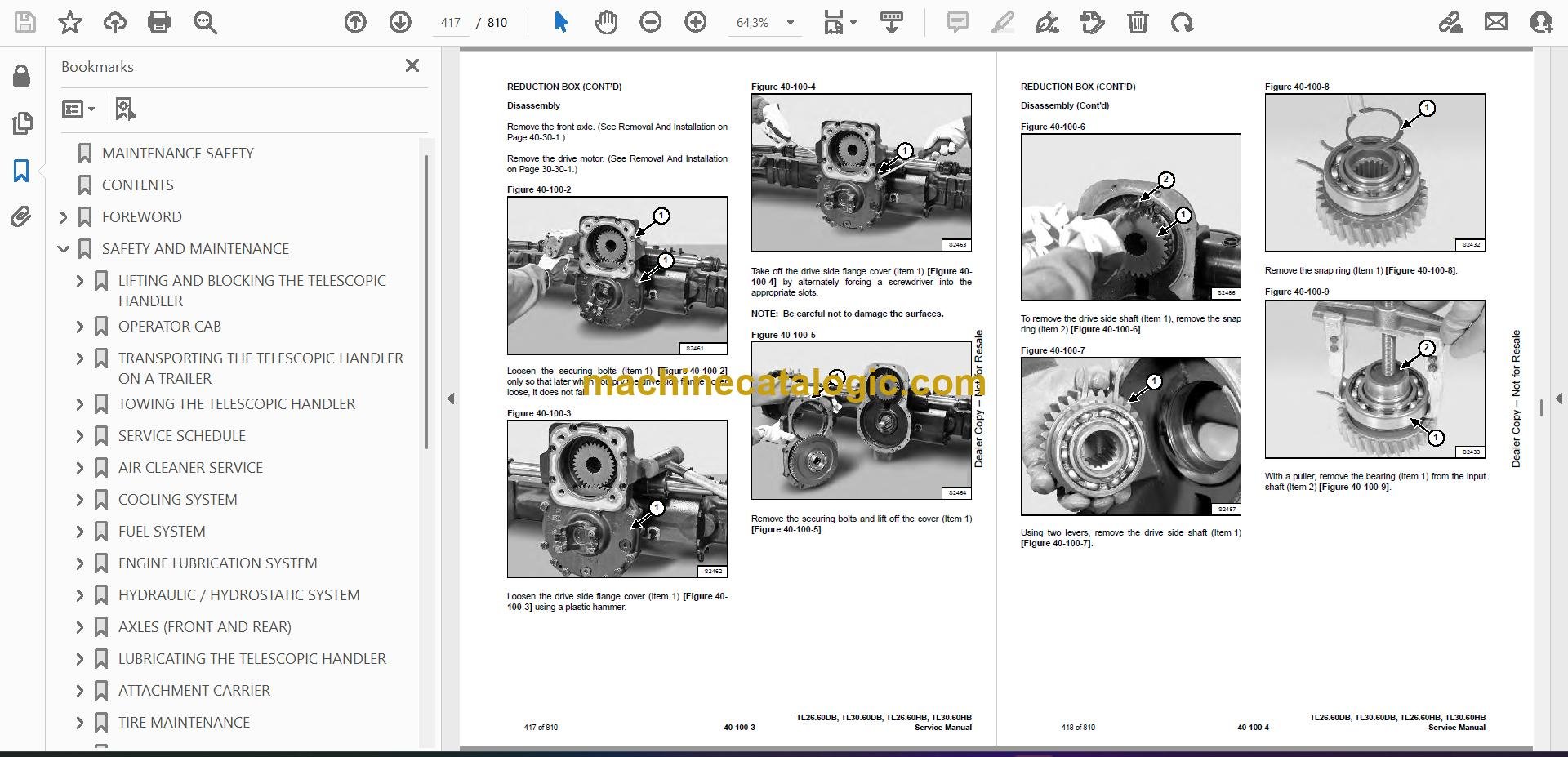
The TL2660 VersaHANDLER is a telescopic handler you'll see on farms, jobsites, and rental yards doing pallet work, loading trucks, and running forks or buckets up high. The service manual is what I reach for around my shop when a machine is out of warranty and I'm chasing a hydraulic issue, an electrical gremlin, or I need the right teardown order. Buyers usually want this manual when they're tired of guessing and want the factory way to diagnose and reassemble things without wrecking parts or burning downtime.

What this manual helps you do

  • Diagnose hydraulic problems, check pressures, and trace leaks in the boom and stabilizer circuits
  • Troubleshoot electrical faults, follow wiring diagrams, and sort out sensor or switch issues
  • Rebuild or replace driveline and axle components with the right disassembly and reassembly steps
  • Adjust boom, steering, and brake systems so they're within spec after repairs
  • Verify safety and load-handling systems after component changes or accident damage

Who this is for

This is for a small contractor, farm shop, rental fleet, or owner-operator running a Bobcat TL2660 VersaHANDLER TTC with serial numbers in the B3GA14000 to B3GA99999 range. If you only need basic controls, daily checks, or safety info, you want the operator's handbook instead, not this service manual.

FAQ

Q: Is this a searchable PDF, and are the wiring diagrams readable?

A: Yes, these manuals are usually searchable PDFs, and the wiring diagrams are laid out so you can zoom in and read pin numbers and wire colors.

Q: Will this cover my exact TL2660 machine?

A: If your serial number falls between B3GA14000 and B3GA99999, this is the right manual. If it doesn't, you need the matching serial range.

Q: Is this what I need for real repairs, or is it just a parts list?

A: This is the service manual, so it's for diagnostics, teardown, and repair procedures, not for ordering parts and not for basic operation.

Bottom line: If you own or wrench on a TL2660 in that serial range and you're doing your own repairs, this is the manual you want. If you're just learning to run the machine, skip this one.

📘 Show Index

Table of Contents:

  • MAINTENANCE SAFETY
  • CONTENTS
  • FOREWORD
    • FOREWORD
    • SAFETY INSTRUCTIONS
      • Safe Operation Is The Operator’s Responsibility
      • Safe Operation Needs A Qualified Operator
      • Avoid Silica Dust
      • Dismantling And Disposal
    • FIRE PREVENTION
      • Maintenance
      • Operation
      • Electrical
      • Hydraulic System
      • Fueling
      • Starting
      • Welding And Grinding
      • Fire Extinguishers
    • PUBLICATIONS AND TRAINING RESOURCES
    • SERIAL NUMBER LOCATION
      • Telescopic Handler Serial Number
      • Engine Serial Number
      • Other Serial Numbers
    • DELIVERY REPORT
    • BOBCAT TELESCOPIC HANDLER IDENTIFICATION
  • SAFETY AND MAINTENANCE
    • LIFTING AND BLOCKING THE TELESCOPIC HANDLER
      • Procedure
    • OPERATOR CAB
      • Description
      • Cab Door
      • Cab Door Window
      • Rear Cab Window
      • Cab Light
    • TRANSPORTING THE TELESCOPIC HANDLER ON A TRAILER
      • Loading And Unloading
      • Fastening
    • TOWING THE TELESCOPIC HANDLER
      • Procedure
    • SERVICE SCHEDULE
      • Maintenance Intervals
    • AIR CLEANER SERVICE
      • Replacing Filter Elements
    • COOLING SYSTEM
      • Cleaning
      • Checking Level
      • Removing And Replacing The Coolant
    • FUEL SYSTEM
      • Fuel Specifications
      • Biodiesel Blend Fuel
      • Filling The Fuel Tank
      • Primary Fuel Filter (Pre-Filter)
      • Secondary Fuel Filter
      • Removing Air From The Fuel System
    • ENGINE LUBRICATION SYSTEM
      • Checking And Adding Engine Oil
      • Engine Oil Chart
      • Removing And Replacing Oil And Filter
    • HYDRAULIC / HYDROSTATIC SYSTEM
      • Checking And Adding Fluid
      • Removing And Replacing Hydraulic Fluid
      • Removing And Replacing Hydraulic / Hydrostatic Filters
      • Fill / Breather Cap
    • AXLES (FRONT AND REAR)
      • Checking And Adding Oil (Planetary Carrier)
      • Removing And Replacing Oil (Planetary Carrier)
      • Checking And Adding Oil (Rear Differential)
      • Removing And Replacing Oil (Rear Differential)
      • Checking And Adding Oil (Front Differential)
      • Removing And Replacing Oil (Front Differential)
      • Checking And Adding Oil (Reduction Box)
      • Removing And Replacing Oil (Reduction Box)
    • LUBRICATING THE TELESCOPIC HANDLER
      • Lubrication Locations
    • ATTACHMENT CARRIER
      • Inspection And Maintenance
    • TIRE MAINTENANCE
      • Wheel Nuts
      • Rotating
      • Wheel Replacement
      • Mounting
      • Pressure
    • APPROVED BOOM STOP
      • Installing The Approved Boom Stop
      • Removing The Approved Boom Stop
    • ENGINE COVER
      • Opening And Closing
    • STOPPING THE ENGINE AND LEAVING THE TELESCOPIC HANDLER
      • Procedure
    • EMERGENCY EXIT
      • Rear Window
    • TELESCOPIC HANDLER STORAGE AND RETURN TO SERVICE
      • Storage
      • Return To Service
    • LIFTING THE TELESCOPIC HANDLER
      • Procedure
    • REMOTE START TOOL (SERVICE TOOL) KIT – 6987761
      • Remote Start Tool (Service Tool) – 7022042
      • Telescopic Handler Service Tool Harness – 6689747
      • Computer Service Tool Harness – 6689746
      • Remote Start Procedure
  • HYDRAULIC SYSTEM
    • HYDRAULIC / HYDROSTATIC SCHEMATICS
    • HYDRAULIC SYSTEM INFORMATION
      • Glossary Of Hydraulic / Hydrostatic Symbols
      • Troubleshooting Chart
      • Tightening Procedures
      • Test Coupler Location
    • BOOM CYLINDER
      • Removal And Installation
      • Parts Identification
      • Disassembly
      • Assembly
    • SELF-LEVELING (COMPENSATION) CYLINDER
      • Removal And Installation
      • Parts Identification
      • Disassembly
      • Assembly
    • EXTENSION (COMPENSATION) CYLINDER
      • Removal And Installation
      • Parts Identification
      • Disassembly
      • Assembly
    • TILT CYLINDER
      • Removal And Installation
      • Parts Identification
      • Disassembly
      • Assembly
    • STEERING CYLINDER (FRONT / REAR)
      • Removal
      • Installation
      • Disassembly
      • Assembly
    • BRAKES BLOCK
      • Removing And Installing The Standard Brakes Block
    • ACCUMULATORS
      • Accumulators Pressure Relief
      • Removing And Installing The Boom Suspension Valve Accumulators
    • SERVICE BRAKE VALVE
      • Removal And Installation
    • TANDEM GEAR PUMP
      • Removal And Installation
      • Parts Identification
      • Disassembly And Assembly
    • FAN MOTOR
      • Description
      • Removal And Installation
      • Parts Identification (Single Speed Version) (Standard)
      • Disassembly And Assembly (Single Speed Version) (Standard)
      • Parts Identification (Variable Speed Version)
      • Disassembly And Assembly (Variable Speed Version)
    • HYDRAULIC FLUID TANK
      • Removal And Installation
    • STEERING UNIT
      • Removal And Installation
    • MAIN VALVE
      • Troubleshooting Chart (Solenoid Valves)
      • Valve Section Troubleshooting
      • Troubleshooting Chart (Main Valve)
      • Removal And Installation
      • Parts Identification
      • Section Removal
      • Section Disassembly And Assembly
      • Inlet-Outlet Valve Section Disassembly And Assembly
      • End Housing Disassembly And Assembly
    • PORT RELIEF VALVES
      • Removal And Installation
    • AUXILIARY HYDRAULIC FLOW
      • Testing The Auxiliary Hydraulic Flow
    • STEERING MODE VALVE
      • Removal And Installation
    • POWER LIFT VALVE
      • Removal And Installation
    • BOOM SUSPENSION AND FLOAT SYSTEM
      • Boom Suspension Functional Description
      • Boom Float Functional Description
      • Removing And Installing The Boom Suspension Valve
  • HYDROSTATIC SYSTEM
    • HYDROSTATIC SYSTEM INFORMATION
      • Troubleshooting Chart
      • Test Coupler Location
    • OIL COOLER
      • Description
    • HYDROSTATIC DRIVE MOTOR
      • Removal And Installation
      • Parts Identification
      • Disassembly
      • Inspection
      • Assembly
    • HYDROSTATIC PUMP
      • Removal And Installation
      • Parts Identification
      • Shaft Disassembly
      • Relief Valves Disassembly And Assembly
      • Charge Pump Disassembly
      • Piston Pump Disassembly
      • Solenoid Block Disassembly
      • Inspection
      • Piston Pump Assembly
      • Charge Pump Assembly
      • Solenoid Block Assembly
      • Shaft Assembly
  • DRIVE SYSTEM
    • DRIVE SYSTEM TROUBLESHOOTING
      • Chart
    • AXLE AND DIFFERENTIAL (FRONT)
      • Description
      • Planetary Carrier, Wheel Hub And Drive Axle Parts Identification
      • Planetary Carrier Disassembly
      • Wheel Hub Disassembly
      • Drive Axle Disassembly
      • Steering Knuckle Parts Identification
      • Steering Knuckle Disassembly
      • Brake Group Parts Identification
      • Brake Group Disassembly
      • Differential Parts Identification
      • Differential Disassembly
      • Pinion Group Parts Identification
      • Pinion Group Disassembly
      • Pinion Group Assembly
      • Differential Assembly
      • Brake Group Assembly
      • Axle Housing / Drive Axle Assembly
      • Steering Knuckle Assembly
      • Wheel Hub Assembly
      • Planetary Carrier Assembly
    • AXLE AND DIFFERENTIAL (REAR)
      • Description
      • Planetary Carrier, Wheel Hub And Drive Axle Parts Identification
      • Planetary Carrier Disassembly
      • Wheel Hub Disassembly
      • Steering Knuckle Parts Identification
      • Steering Knuckle Disassembly
      • Axle Housing / Drive Axle Disassembly
      • Differential And Pinion Group Parts Identification
      • Pinion Group Disassembly
      • Pinion Group Assembly
      • Differential Assembly
      • Steering Knuckle Assembly
      • Planetary Carrier Assembly
    • FRONT AXLE
      • Removal And Installation
    • AXLE TOE-IN
      • Adjustment
    • PARK BRAKE
      • Park Brake Removal, Disassembly And Assembly
    • STEERING ANGLE ADJUSTMENT
      • Adjustment
    • DRIVESHAFT
      • Removal And Installation
    • SERVICE BRAKE
      • Description
      • Bleeding The Brake Circuit
    • REAR AXLE
      • Removal And Installation
    • REDUCTION BOX
      • Removal And Installation
      • Parts Identification
      • Disassembly
      • Assembly
  • MAINFRAME
    • OPERATOR CAB
      • Removal And Installation
    • OPERATOR SEAT
      • Removal And Installation
    • BOOM ASSEMBLY
      • Removal And Installation
    • BOOM TRAY
      • Removal And Installation
      • Upper Tubeline Removal
      • Upper Tubeline Installation
      • Tubeline Tray Disassembly
      • Tubeline Tray Assembly
    • INNER BOOM
      • Removal
      • Installation
    • WEAR PADS (FRONT)
      • Boom Wear Pad Checking
      • Removal
      • Installation
    • WEAR PADS (REAR)
      • Boom Wear Pad Checking
      • Removal
      • Installation
    • ENGINE COVER
      • Gas Cylinder Removal And Installation
      • Removal And Installation
    • FUEL TANK
      • Removal And Installation
    • ATTACHMENT CARRIER (QUICK-TACH)
      • Removal And Installation
    • COUNTERWEIGHT
      • Removal And Installation
    • FENDER
      • Removal And Installation
    • STEERING COLUMN COVER
      • Removal And Installation
    • DASH COVER
      • Removal And Installation
    • JOYSTICK PANEL
      • Removal And Installation
  • ELECTRICAL SYSTEM AND ANALYSIS
    • ELECTRICAL SCHEMATICS
    • ELECTRICAL SYSTEM INFORMATION
      • Glossary Of Electrical Symbols
      • Cab Harness Connectors
      • Mainframe Harness Connectors
      • Engine Bay Harness Connectors
      • Troubleshooting Chart
      • Description
      • Fuses And Relay Location / Identification
    • BATTERY
      • Removal And Installation
      • Using A Booster Battery (Jump Starting)
    • ALTERNATOR
      • Inspection
      • Removal And Installation
      • Belt Adjustment
      • Belt Checking
      • Belt Replacement
    • STARTER
      • Testing
      • Removal And Installation
    • LIGHTS
      • Rear Light Removal And Installation
      • Front Light Removal And Installation
    • SIGNAL LEVER
      • Removal And Installation
    • DISPLAY
      • Removal And Installation
    • INSTRUMENT PANEL
      • Removal And Installation
    • BOOM ANGLE SENSOR
      • Description
      • Removal And Installation
    • FRONT WIPER MOTOR
      • Removal And Installation
    • TOP WIPER MOTOR
      • Removal And Installation
    • REAR WIPER MOTOR
      • Removal And Installation
    • SERVICE BRAKE PEDAL ASSEMBLY
      • Removal And Installation
    • INCHING SENSOR
      • Description
      • Removal And Installation
    • EMERGENCY BRAKE
      • Description
    • SERVICE PC (LAPTOP COMPUTER)
      • Connecting Remote Start Tool (Service Tool) – 6987761
    • FUEL LEVEL SENDER
      • Removal And Installation
    • JOYSTICK
      • Removal And Installation
    • LLMI / LLMC SYSTEM
      • System Components Identification
      • LLMS Removal
      • LLMS Installation
      • LLMC Removal And Installation
    • TRAVEL DIRECTION LEVER
      • Removal And Installation
    • CONTROLLERS
      • Description
      • Gateway Controller
      • Drive Controller
      • Workgroup Controller
      • Display Controller
      • LLMI Controller
      • LLMC Controller
    • MAINTENANCE CLOCK
      • Description
      • Setup
      • Reset
    • AUTOMATIC PARK BRAKE
      • Description
    • CALIBRATION
      • Calibrating The Hydrostatic Pump
      • Calibrating The Boom Angle Sensor
      • Calibrating The Lift Coils
      • Calibrating The Inching Sensor
      • Calibrating The LLMC System
      • LLMC Calibration Test
      • LLMI / LLMC System Failure Reports
  • ENGINE SERVICE
    • ENGINE
      • Specifications
      • Troubleshooting
      • Engine Removal And Installation
      • Compression Checking
    • ENGINE BAY ASSEMBLY
      • Removal And Installation
    • ENGINE SPEED CONTROL
      • Removal And Installation
    • MUFFLER
      • Removal And Installation
    • AIR CLEANER
      • Housing Removal And Installation
    • COOLING SYSTEM
      • Oil Cooler / Intercooler / Radiator Removal And Installation
      • Cooling System Description
      • Thermostat Removal And Installation
      • Thermostat Testing
      • Lubricating Oil Cooler Removal And Installation
      • Water Pump Removal
      • Water Pump Installation
      • Expansion Tank Removal And Installation
    • LUBRICATION SYSTEM
      • Engine Lubrication System Description
      • Oil Filter Adapter Removal And Installation
      • Oil Pan Removal And Installation
      • Oil Screen And Pick-up Tube
      • Oil Pump Removal
      • Oil Pump Installation
      • Oil Pump Disassembly And Assembly
      • Oil Pressure Relief Valve Disassembly And Assembly
    • FUEL SYSTEM
      • Fuel Injection Pump Removal
      • Fuel Injection Pump Installation
      • Fuel Injectors Removal And Installation
      • Checking The Fuel Lift Pump
      • Fuel Lift Pump Removal And Installation
      • Exhaust Manifold Removal And Installation
      • Fuel Injector Cover Removal And Installation
      • Rocker Cover Removal And Installation
    • CYLINDER HEAD
      • Glow Plugs Checking
      • Glow Plugs Removal And Installation
      • Removal
      • Inspection
      • Installation
      • Rocker Shaft Disassembly And Assembly
      • Valve Removal
      • Valve Springs Checking
      • Valve Depth Checking
      • Valve Guide Checking
      • Valve Guide Removal
      • Valve Guide Installation
      • Valve Checking
      • Cutting A Valve Seat
      • Valve Seat Assembly
      • Changing Valve Springs (With Cylinder Head Installed)
      • Valve Clearance Adjustment
      • Engine Block Description
      • Engine Block Disassembly And Assembly
      • Engine Block Inspection
      • Cylinder Liner Inspection
      • Cylinder Liner Removal
      • Cylinder Liner Installation
    • CRANKSHAFT AND PISTONS
      • Pistons And Connecting Rods Description
      • Pistons And Connecting Rods Removal
      • Pistons And Connecting Rods Disassembly
      • Piston Ring End Gap
      • Piston Ring Installation
      • Piston Ring Groove Clearance
      • Piston Cooling Jet Removal
      • Piston Cooling Jet Installation
      • Piston Cooling Jet Alignment
      • Connecting Rod Inspection
      • Connecting Rod Bushing Replacement
      • Piston And Connecting Rod Assembly
      • Piston And Connecting Rod Installation
      • Checking Piston Height
      • Crankshaft And Bearings Description
      • Crankshaft And Bearings Removal
      • Inspection Of Crankshaft And Bearings
      • Crankshaft And Bearings Installation
      • Rear Oil Seal Removal
      • Rear Oil Seal Housing Positioning
      • Rear Oil Seal Installation
      • Checking Crankshaft End Play
    • CAMSHAFT AND TIMING GEARS
      • Engine Timing Procedure
      • Timing Case And Drive Assembly Description
      • Timing Cover Removal
      • Timing Cover Installation
      • Crankshaft Pulley Removal And Installation
      • Front Oil Seal Removal And Installation
      • Timing Case And Gear Removal
      • Timing Case And Gear Installation
      • Camshaft And Tappets Removal
      • Camshaft And Tappets Installation
    • TURBOCHARGER
      • Troubleshooting
      • Description
      • Removal And Installation
    • FLYWHEEL AND HOUSING
      • Removal And Installation
      • Flywheel Inspection
      • Ring Gear Removal
      • Ring Gear Installation
  • HEATING, VENTILATION, AIR CONDITIONING (HVAC)
    • AIR CONDITIONING SYSTEM FLOW
      • Description
      • Chart
      • Components
      • Safety Equipment
    • REGULAR MAINTENANCE
      • Cab Filter
      • A/C System Water Condensate Rubber Valves
      • Belt Adjustment
      • Belt Replacement
      • Cleaning The Condenser
      • Air Conditioning Lubrication
      • Air Conditioning Service Chart
    • A/C SYSTEM TROUBLESHOOTING
      • Blower Motor Does Not Operate
      • Blower Motor Operates Normally, But Air Flow Is Insufficient
      • Insufficient Cooling Although Air Flow And Compressor Operation Are Normal
      • The Compressor Does Not Operate At All, Or Operates Improperly
      • Gauge Pressure Related Troubleshooting
      • Temperature / Pressure Chart
      • Poor A/C Performance
      • HVAC Repair And Leaks
      • Electrical System
    • SYSTEM CHARGING AND RECLAMATION
      • Reclamation And Charging With Recovery / Charging Unit
    • COMPRESSOR
      • Removal And Installation
      • Oil
      • Oil Check
      • Clutch Disassembly And Assembly
    • CONDENSER
      • Removal And Installation
    • RECEIVER / DRIER
      • Removal And Installation
    • PRESSURE SWITCH
      • Removal And Installation
    • EVAPORATOR / HEATER UNIT
      • Removal And Installation
    • THERMOSTAT
      • Description
      • Removal And Installation
    • EXPANSION VALVE
      • Removal And Installation
  • SPECIFICATIONS
    • TL26.60DB, TL26.60HB TELESCOPIC HANDLER SPECIFICATIONS
      • Machine Dimensions For Models TL26.60DB
      • Machine Dimensions For Models TL30.60HB
      • Performance
      • Weights
      • Engine
      • Controls
      • Drive System
      • Traction
      • Steering
      • Brakes
      • Fluid Capacities
      • Hydraulic System
      • Electrical System
      • Temperature Range
      • Altitude
      • Instrument Panel
      • Environmental*
    • TL30.60DB, TL30.60HB TELESCOPIC HANDLER SPECIFICATIONS
      • Machine Dimensions For Models TL30.60DB
      • Machine Dimensions For Models TL30.60HB
      • Performance
      • Weights
      • Engine
      • Controls
      • Drive System
      • Traction
      • Steering
      • Brakes
      • Fluid Capacities
      • Hydraulic System
      • Electrical System
      • Temperature Range
      • Altitude
      • Instrument Panel
      • Environmental*
    • VISIBILITY DIAGRAMS
      • Visibility Diagrams For Models TL26.60DB – 20” Wheels*
      • Visibility Diagrams For Models TL26.60DB – 24” Wheels*
      • Visibility Diagrams For Models TL26.60HB – 20” Wheels*
      • Visibility Diagrams For Models TL26.60HB – 24” Wheels*
      • Visibility Diagrams For Models TL30.60DB – 20” Wheels*
      • Visibility Diagrams For Models TL30.60DB – 24” Wheels*
      • Visibility Diagrams For Models TL30.60HB – 20” Wheels*
      • Visibility Diagrams For Models TL30.60HB – 24” Wheels*
      • Visibility Diagrams For Light Material Buckets*
    • LIFTING AND TIE-DOWN SPECIFICATIONS
      • Lifting
      • Tie Down
    • MACHINE TORQUE SPECIFICATIONS
      • Axle
      • Boom
      • Reduction Box
      • Drive Motor
      • Engine
      • Hydraulic Pump
    • TORQUE SPECIFICATIONS FOR BOLTS
      • Torque For General SAE Bolts
      • Torque For General Metric Bolts
    • HYDRAULIC CONNECTION SPECIFICATIONS
      • O-ring Face Seal Connection
      • Straight Thread O-ring Fitting
      • Tubelines And Hoses
      • Flare Fitting
      • O-ring Flare Fitting
      • Port Seal Fitting
    • HYDRAULIC / HYDROSTATIC FLUID SPECIFICATIONS
      • Specifications
    • CONVERSIONS
      • Decimal And Millimeter Equivalent Chart
      • U.S. To Metric Conversion Chart
    • SERVICE TOOLS REQUIRED
      • Remote Start Tools
      • Hydraulic Tools
      • Electrical Tools
      • Engine Tools
      • Special Drive Tools
  • ALPHABETICAL INDEX

Bobcat Software

Bobcat PDF Manuals

Related Manuals

0
    0
    Your Cart
    Your cart is emptyReturn to Shop