$ 0
0
$ 0
0

Bobcat BL275 Backhoe Loader Service Manual (SN 570811001-570899999)

Format: PDF (Printable Document)

File Language: English

File Pages: 796

File Size: 25.62 MB (Speed Download Link)

Brand: Bobcat

Model: BL275 Backhoe Loader

Book No: 6901968

Serial No: SN 570811001-570899999

Type of Document: Service Manual

Categories: ,

$ 45

Share:

Bobcat BL275 Backhoe Loader Service Manual (SN 570811001-570899999)

Out on a job, the BL275 is your all-in-one: you're loading trucks on the front and trenching or setting utilities on the backhoe. The person who reaches for this manual is the one actually fixing the machine, not just running it. They're trying to cut dealer bills, get solid specs, and get a dead loader/backhoe back to work without guessing. Around my shop, this is what I'd have open when I've got the hood up and tools out.

What this manual helps you do

  • Diagnose hydraulic issues on the loader and backhoe circuits, then check pressures and isolate bad valves or cylinders
  • Trace electrical faults using wiring diagrams so you can chase down no-starts, dead lights, or sensor problems
  • Follow step-by-step teardown and reassembly of major components like axles, brakes, loader arms, and the backhoe boom
  • Replace engine and drivetrain parts with the right sequences and torque specs, instead of guessing and redoing work
  • Adjust linkages, controls, and relief settings so the machine digs, lifts, and steers the way it should after repairs

Who this is for

This is for a small contractor, owner-operator, rental fleet shop, or field tech working on a Bobcat BL275 in the serial range 570811001 to 570899999. If you just need to learn how to run the machine or see part numbers, you want the operator's handbook or the parts catalog instead.

FAQ

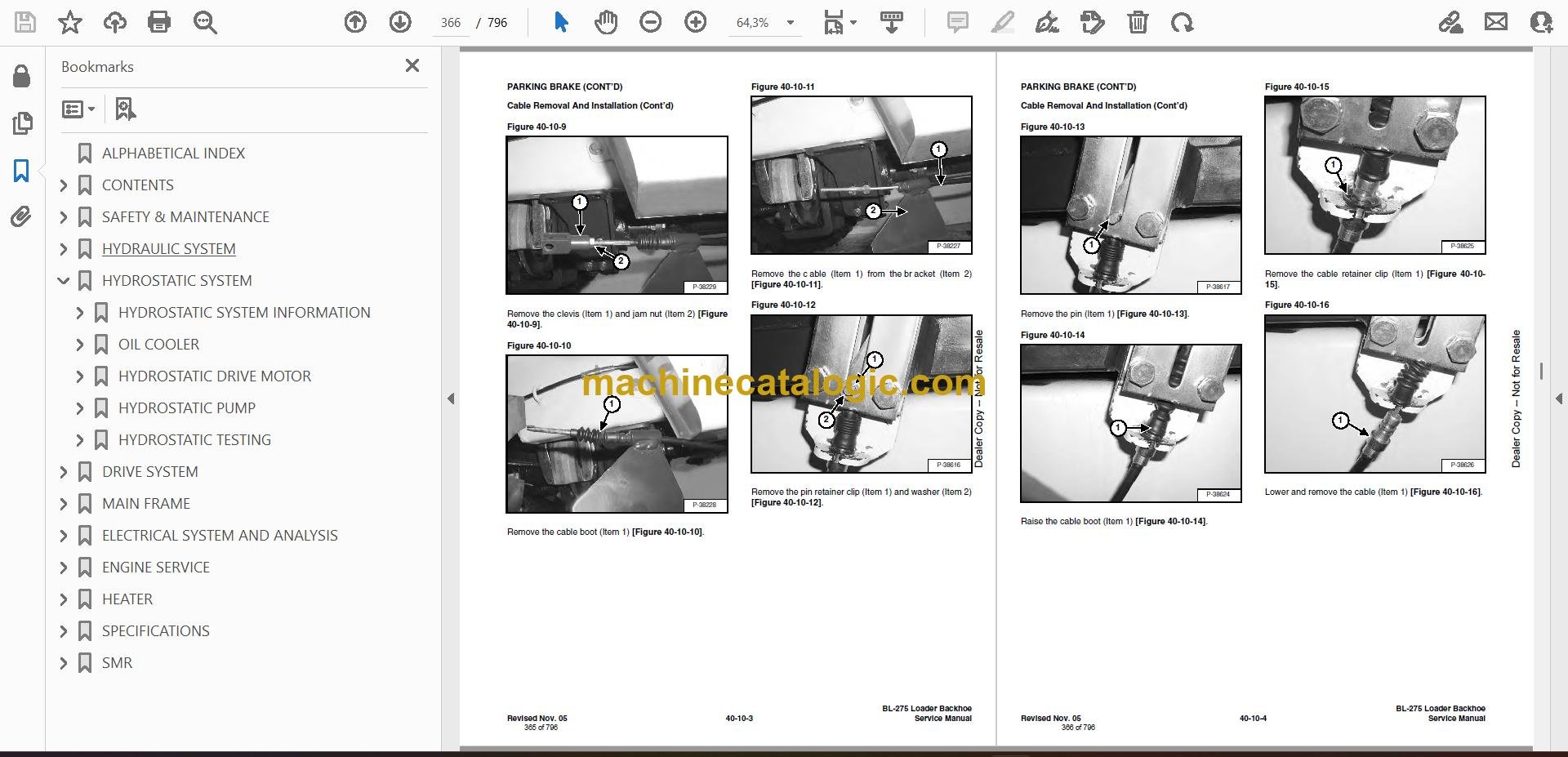
Q: Is this a searchable PDF, and can you read the wiring diagrams?

A: Yes, it's a PDF, and you can zoom in on schematics and wiring diagrams so they're actually readable on a laptop or tablet.

Q: How do I know if it covers my exact BL275?

A: Check your machine's serial number plate. If it falls between 570811001 and 570899999, this is the right manual.

Q: Is this the right thing if I'm doing real repairs, not just maintenance?

A: Yes, this is the workshop service manual, meant for diagnostics and repairs, not just basic fluid changes.

Bottom line, if your BL275's serial number is in that range and you're turning wrenches on it yourself, this is the manual you want. If not, keep looking for the correct serial range.

📘 Show Index

Table of Contents:

  • ALPHABETICAL INDEX
  • CONTENTS
    • FOREWORD
    • SAFETY INSTRUCTIONS FOR INGERSOLL RAND LOADER BACKHOE AND ATTACHMENTS
    • SAFE OPERATION IS THE OPERATOR’S RESPONSIBILITY
    • FIRE PREVENTION
    • SERIAL NUMBER LOCATION
      • Loader Backhoe Serial Number
      • Engine Serial Number
    • DELIVERY REPORT
    • INGERSOLL RAND LOADER IDENTIFICATION
  • SAFETY & MAINTENANCE
    • LIFTING AND BLOCKING THE LOADER BACKHOE
      • Procedure
    • LIFT ARM SUPPORT DEVICE
      • Installing The Lift Arm Support Device
      • Removing The Lift Arm Support Device
    • ENGINE COVER
    • TRANSPORTING THE LOADER BACKHOE
      • Procedure
    • TOWING THE LOADER BACKHOE
      • Procedure
    • AXLE TOE-IN
      • Adjustment
    • SERVICE SCHEDULE
      • Chart
    • AIR CLEANER SERVICE
      • Replacing Filter Element
    • ENGINE COOLING SYSTEM
      • Coolant Replacement
    • FUEL SYSTEM
      • Fuel Specifications
      • Filling The Fuel Tank
      • Fuel Filter
      • Removing Air From The Fuel System
    • ENGINE LUBRICATION SYSTEM
      • Checking Engine Oil
      • Oil Chart
      • Replacing Oil And Filter
    • HYDRAULIC/HYDROSTATIC SYSTEM
      • Checking And Adding Fluid
      • Cleaning The Cooler
      • Replacing Hydraulic/Hydrostatic Filter
      • Replacing Hydraulic Fluid
    • REAR AXLE
      • Checking Oil Level
      • Draining Oil
    • FRONT AXLE
      • Checking Oil Level
      • Draining Oil
    • BACKHOE BOOM LOCK
      • Disengaging The Boom Lock
      • Engaging Boom Lock
    • BOB-TACH HAND LEVER
      • Inspection And Maintenance
    • ALTERNATOR BELT
      • Adjusting The Alternator Belt
    • LUBRICATING THE LOADER BACKHOE
    • TIRE MAINTENANCE
      • Wheel Nuts
      • Mounting
      • Tire Pressure
  • HYDRAULIC SYSTEM
    • HYDRAULIC SCHEMATICS
    • HYDRAULIC SYSTEM INFORMATION
      • Troubleshooting
      • Description
    • ARM CYLINDER
      • Checking
      • Removal And Installation
      • Parts Identification
      • Disassembly
      • Assembly
    • BOOM CYLINDER
      • Checking
      • Removal And Installation
      • Parts Identification
      • Disassembly
      • Assembly
    • SWING CYLINDER
      • Removal And Installation
      • Parts Identification (Left Side)
      • Parts Identification (Right Side)
      • Disassembly
      • Assembly
    • BUCKET CYLINDER
      • Checking
      • Removal And Installation
      • Parts Identification
      • Disassembly
      • Assembly
    • STABILIZER CYLINDER
      • Checking
      • Removal And Installation
      • Parts Identification
      • Disassembly
      • Assembly
    • SIDE SHIFT LOCK CYLINDER
      • Disassembly
      • Inspection
      • Assembly
      • Parts Identification
    • TILT CYLINDER
      • Checking
      • Removal And Installation
      • Parts Identification (Left Side)
      • Parts Identification (Right Side)
      • Disassembly
      • Assembly
    • LIFT CYLINDER
      • Checking
      • Removal And Installation
      • Parts Identification
      • Disassembly
      • Assembly
    • STEERING CYLINDER (FRONT)
      • Removal And Installation
      • Parts Identification
      • Disassembly And Assembly
      • Inspection
    • STEERING CYLINDER (REAR)
      • Removal And Installation
      • Parts Identification
      • Disassembly And Assembly
      • Inspection
    • MAIN RELIEF VALVE
      • Testing The Main Relief Valve
      • Adjustment
    • PORT RELIEF VALVE (BACKHOE CONTROL VALVE)
      • Testing And Adjusting (Arm Control)
      • Testing And Adjusting (Boom Control)
      • Testing And Adjusting (Boom Swing Control)
    • PORT RELIEF VALVE (LOADER CONTROL VALVE)
      • Testing And Adjusting (Bucket Tilt)
      • Testing And Adjusting (Front Auxiliary)
    • LOADER CONTROL VALVE
      • Removal And Installation
      • Parts Identification
      • Disassembly And Assembly
      • Inlet/Outlet Valve Section
      • Lift Arm Valve Section
      • Tilt Valve Section
      • Auxiliary Valve Section
    • BACKHOE CONTROL VALVE
      • Removal And Installation
      • Parts Identification
      • Disassembly And Assembly
      • Inlet/Outlet Valve Section
      • Arm Valve Section
      • Tilt Valve Section
      • Right Stabilizer Valve Section
      • Left Stabilizer Valve Section
      • Boom Valve Section
      • Boom Swing Valve Section
      • Outlet Valve Section
    • HYDRAULIC FLUID RESERVOIR
      • Removal And Installation
      • Filter Removal And Installation
    • HYDRAULIC FILTER HOUSING
      • Removal And Installation
      • Disassembly
      • Assembly
    • GEAR PUMP
      • Removal And Installation
      • Parts Identification
      • Disassembly And Assembly
      • Inspection
    • STEERING PUMP
      • Removal And Installation
      • Parts Identification
      • Disassembly
      • Inspection
      • Assembly
    • TRAVEL PEDAL
      • Removal And Installation
      • Parts Identification
      • Disassembly And Assembly
    • STEERING VALVE
      • Removal And Installation
      • Description
      • Wheel Alignment Procedure
  • HYDROSTATIC SYSTEM
    • HYDROSTATIC SYSTEM INFORMATION
      • Troubleshooting Chart
      • Replenishing Valve Function
    • OIL COOLER
      • Removal And Installation
      • Parts Identification
      • Disassembly
      • Assembly
    • HYDROSTATIC DRIVE MOTOR
      • Removal And Installation
      • Parts Identification
      • Disassembly
      • Inspection
      • Assembly
    • HYDROSTATIC PUMP
      • Removal And Installation
      • Parts Identification
      • Disassembly
      • Inspection
      • Assembly
    • HYDROSTATIC TESTING
      • Pump Adjustment
  • DRIVE SYSTEM
    • PARKING BRAKE
      • Lever Removal And Installation
      • Cable Removal And Installation
      • Adjustment
    • BRAKE CALIPER
      • Removal And Installation
      • Parts Identification
      • Disassembly And Assembly
    • BRAKE CALIPER
      • Removal And Installation
      • Parts Identification
      • Disassembly And Assembly
    • REAR AXLE
      • Removal
      • Installation
    • AXLE AND DIFFERENTIAL (REAR)
      • Troubleshooting Chart
      • General Information
      • Wheel Hub/Spindle Parts Identification
      • Wheel Hub/Spindle Disassembly
      • Drive Axle Parts Identification
      • Drive Axle Disassembly
      • Steering Knuckle Parts Identification
      • Steering Knuckle Disassembly
      • Differential Parts Identification
      • Differential Disassembly
      • Differential Inspection
      • Pinion Group Parts Identification
      • Pinion Group Disassembly
      • Pinion Group Inspection
      • Pinion Group Assembly
      • Differential Assembly
      • Steering Knuckle Assembly
      • Drive Axle Assembly
      • Wheel Hub/Spindle Assembly
    • STEERING ANGLE ADJUSTMENT (REAR AXLE)
      • Adjustment
    • FRONT AXLE
      • Removal
      • Installation
    • AXLE AND DIFFERENTIAL (FRONT)
      • Troubleshooting Chart
      • General Information
      • Wheel Hub/Spindle Parts Identification
      • Wheel Hub/Spindle Disassembly
      • Drive Axle Parts Identification
      • Drive Axle Disassembly
      • Steering Knuckle Parts Identification
      • Steering Knuckle Disassembly
      • Differential Parts Identification
      • Differential Disassembly
      • Differential Inspection
      • Pinion Group Parts Identification
      • Pinion Group Disassembly
      • Pinion Group Inspection
      • Pinion Group Assembly
      • Differential Assembly
      • Steering Knuckle Assembly
      • Drive Axle Assembly
      • Wheel Hub/Spindle Assembly
    • STEERING ANGLE ADJUSTMENT (FRONT AXLE)
      • Adjustment
    • DRIVESHAFT
      • Removal And Installation
    • DROP BOX
      • Removal And Installation
      • Parts Identification
      • Disassembly
      • Inspection
      • Assembly
  • MAIN FRAME
    • OPERATOR CAB
      • Not Available At Time Of Printing
    • ENCLOSED CAB
      • Removal And Installation
      • Cab Mount Removal And Installation
    • OPERATOR SEAT
      • Removal And Installation
    • FLOOR PANELS
      • Left Front Panel Removal And Installation
      • Right Front Panel Removal And Installation
      • Rear Panel Removal And Installation
    • GRILL
      • Removal And Installation
    • GRILL FRAME
      • Removal And Installation
    • ENGINE SIDE COVERS
      • Removal And Installation
    • FENDER
      • Removal And Installation
    • ENGINE COVER
      • Removal And Installation
    • FUEL TANK
      • Removal And Installation
      • Fuel Fill Screen Removal And Installation
    • LIFT ARMS
      • Removal And Installation
    • BOB-TACH
      • Removal And Installation
      • Bob-Tach Lever And Wedge
      • Pivot Pin Bushing Removal And Installation
    • ARM
      • Removal And Installation
      • Arm Pivot Bushing Removal And Installation
    • BOOM
      • Removal And Installation
    • SWING FRAME
      • Removal And Installation
      • Bushing Removal And Installation
    • X-CHANGE™
      • Removal And Installation
    • BUCKET
      • Backhoe Bucket Teeth Removal And Installation
      • Loader Bucket Teeth Removal And Installation
    • STABILIZER FRAME
      • Removal And Installation
    • FRONT AXLE PIVOT FRAME
      • Removal
      • Installation
      • Bushing Removal And Installation
    • REAR WINDOW
      • Removal And Installation
    • CAB DOOR
      • Removal And Installation
  • ELECTRICAL SYSTEM AND ANALYSIS
    • ELECTRICAL SCHEMATICS
    • ELECTRICAL SYSTEM INFORMATION
      • Troubleshooting Chart
      • Description
      • Fuse Location
    • BATTERY
      • Removal And Installation
      • Servicing The Electrical System
      • Using A Booster Battery (Jump Starting)
    • ALTERNATOR
      • Adjusting The Alternator Belt
      • Description
      • Tests
      • Alternator Output Test
      • Full Field Test
      • Alternator Regulator Test
      • Alternator Regulator Test With Voltmeter
      • Removal And Installation
      • Parts Identification
      • Pulley Removal And Installation
      • Disassembly And Assembly
      • Rotor Continuity Test
      • Stator Continuity Test
      • Rectifier Continuity (Diode) Test
      • Brush Length
    • STARTER
      • Removal And Installation
      • Checking The Starter In The Loader
      • Parts Identification
      • Disassembly
      • Inspection And Repair
      • No Load Test
      • Assembly
    • FRONT LIGHTS
      • Bulb Removal And Installation
      • Housing Removal And Installation
    • TURN INDICATOR LIGHTS (FRONT)
      • Bulb Removal And Installation
    • TURN INDICATOR LIGHTS (REAR)
      • Bulb Removal And Installation
    • CAB LIGHTS
      • Bulb Removal And Installation
      • Housing Removal And Installation
    • FUEL LEVEL SENDER
      • Removal And Installation
    • INSTRUMENT PANEL
      • Removal And Installation
    • FRONT WIPER
      • Removal And Installation
    • REAR WIPER
      • Removal And Installation
  • ENGINE SERVICE
    • TROUBLESHOOTING
      • Chart
    • ENGINE SPEED CONTROL
      • Removal And Installation
      • Cable Removal And Installation
    • MUFFLER
      • Removal And Installation
    • AIR CLEANER
      • Removal And Installation
    • RADIATOR
      • Removal And Installation
    • ENGINE COMPONENTS AND TESTING
      • Checking Engine Compression
      • Checking Glow Plugs
      • Glow Plug Removal And Installation
      • Fuel Shut-Off Solenoid Removal And Installation
      • Checking Fuel Injection Pump
      • Fuel Injection Pump Removal And Installation
      • Fuel Injection Pump Timing
      • Fuel Injector Nozzles Removal And Installation
      • Checking Fuel Injector, Nozzles
      • Thermostat Removal And Installation
      • Water Pump Removal And Installation
    • ENGINE
      • Removal And Installation
      • Mount Replacement
    • RECONDITIONING THE ENGINE
      • Timing Gear Case Cover Removal And Installation
      • Oil Pump Removal And Installation
      • Crankshaft Front Seal Removal And Installation
      • Engine Speed Control Plate Removal And Installation
      • Idle Limit And Fuel Limit Adjustment
      • Exhaust Manifold Removal And Installation
      • Valve Cover Removal And Installation
      • Rocker Arm Removal And Installation
      • Push Rod Removal And Installation
      • Tappet Removal And Installation
      • Water Flange Removal And Installation
      • Cylinder Head Removal And Installation
      • Checking Piston Top Clearance
      • Cylinder Head Disassembly And Assembly
      • Servicing The Cylinder Head
      • Combustion Chamber Removal And Installation
      • Idler Gear Removal And Installation
      • Camshaft Removal And Installation
      • Fuel Camshaft Removal And Installation
      • Oil Pan Removal And Installation
      • Governor Shaft Removal And Installation
      • Governor Fork Lever Removal And Installation
      • Piston Removal And Installation
      • Checking The Piston And Connecting Rod
      • Connecting Rod Alignment
      • Piston Ring Gap
      • Piston Ring Installation
      • Connecting Rod Installation
      • Checking Engine Cylinder Bore
      • Crankshaft Removal And Installation
      • Checking Crankshaft Journal And Block Bearing
      • Checking Crankshaft Journal And Main Bearing
      • Connecting Rod Journal
      • Checking The End Play Of The Crankshaft
      • Crankshaft Alignment
      • Engine Timing Installation
      • Timing Gear Backlash, Idler Gear And Crankshaft
      • Idler Gear And Camshaft Gear
      • Idler Gear And Fuel Camshaft Gear
      • Fuel Camshaft Gear And Governor Shaft Gear
    • FLYWHEEL HOUSING
      • Removal And Installation
    • FLYWHEEL
      • Removal And Installation
      • Ring Gear Removal And Installation
    • RUBBER DRIVE COUPLER
      • Removal And Installation
      • Disassembly
    • TURBOCHARGER
      • Removal And Installation
  • HEATER
    • COMPONENTS
      • Identification
    • HEATER FAN
      • Removal And Installation
    • HEATER UNIT
      • Removal And Installation
      • Parts Identification
      • Disassembly And Assembly
  • SPECIFICATIONS
    • LOADER SPECIFICATIONS
      • Loader Backhoe Dimensions
      • Performance
      • Controls
      • Engine
      • Hydraulic System
      • Electrical
      • Drive System
      • Capacities
      • Tires
    • ENGINE SPECIFICATIONS
      • Engine Compression
      • Fuel Injection Nozzles
      • Fuel Injection Pump
      • Cylinder Head
      • Valves
      • Valve Springs
      • Rocker Arms
      • Camshaft
      • Cylinders
      • Piston Rings
      • Pistons
      • Crankshaft
      • Oil Pump
      • Thermostat
      • Grinding Specifications for the Crankshaft
    • LOADER BACKHOE TORQUE
      • Specifications
    • TORQUE SPECIFICATIONS FOR BOLTS
      • Torque For General Metric Bolts
    • HYDRAULIC/HYDROSTATIC FLUID SPECIFICATIONS
      • Specifications
    • CONVERSIONS
      • Decimal And Millimeter Equivalents
      • U.S. To Metric Conversion
  • SMR
    • Revision No: BL-275-1
    • Revision No: BL-275-2
    • Revision No: BL-275-3
    • Revision No: BL-275-4
    • Revision No: BL-275-5

Bobcat Software

Bobcat PDF Manuals

Related Manuals

0
    0
    Your Cart
    Your cart is emptyReturn to Shop