The Bobcat 435 is a compact excavator that lives in tight spots on jobsites, digging footings, trenching utilities, and loading trucks where a big machine just won't fit. The service manual is what I grab when I'm in a customer's driveway or field and need the exact teardown steps, test ports, and specs to get it back digging. Folks use it when they're chasing hydraulic issues, wiring gremlins, or doing engine and final drive work without guessing. If you're past warranty or tired of waiting on a dealer, this is the kind of book you want.
What this manual helps you do
- Diagnose hydraulic problems on the 435, check pressures, and trace leaks or weak functions in the circuits that match this serial range.
- Follow step-by-step removal and installation for components like pumps, drive motors, cylinders, and slew gear without trashing seals or hoses.
- Troubleshoot electrical faults with wiring diagrams sized for screen zooming, so you can track down bad connections and sensors.
- Rebuild and adjust mechanical systems like swing, boom, and track drives with the right sequences and torque references.
- Verify service limits and wear points on pins, bushings, and engine parts before you order anything or wait on a parts run.
Who this is for
This manual is for a shop mechanic, mobile field tech, small contractor, rental fleet, or owner-operator running a Bobcat 435 within serial numbers 563111001 to 563199999. If you just want operating tips, safety info, or daily maintenance charts, you want the operator's handbook instead.
FAQ
Q: Is this a searchable PDF and are the wiring diagrams readable?
A: Yes, these manuals are usually in searchable PDF with diagrams you can zoom on a laptop or tablet in the truck.
Q: Will it cover my exact 435 machine?
A: If your 435 serial number falls between 563111001 and 563199999, this is the right service manual for it.
Q: Is this the right document if I'm doing real repairs, not just greasing and filters?
A: Yes, this is the workshop-level service manual, meant for diagnostics, teardown, and reassembly, not basic operation.
Bottom line, if your 435's serial tag lands in that range and you're doing your own repairs or field diagnostics, this is the manual you want.
📘 Show Index
Table of Contents:
- MAINTENANCE SAFETY
- ALPHABETICAL INDEX
- CONTENTS
- FOREWORD
- SAFETY INSTRUCTIONS
- SERIAL NUMBER LOCATIONS
- Excavator Serial Number
- Engine Serial Number
- DELIVERY REPORT
- BOBCAT EXCAVATOR IDENTIFICATION
- SAFETY AND MAINTENANCE
- LIFTING AND BLOCKING THE EXCAVATOR
- UPPERSTRUCTURE SLEW LOCK
- LIFTING THE EXCAVATOR
- OPERATOR CAB (ROPS/TOPS)
- Emergency Exit (Early Models)
- Emergency Exit (Later Models)
- Cab Door
- Front Window
- Right Side Windows (Early Models)
- Right Side Windows (Later Models)
- TRANSPORTING THE EXCAVATOR
- TAILGATE
- Opening And Closing The Tailgate
- Adjusting The Latch
- RIGHT SIDE COVER
- Opening And Closing The Right Side Cover
- SERVICE SCHEDULE
- AIR CLEANER
- Daily Check
- Replacing The Filters
- HEATER AIR FILTER (WITH CAB OPTION ONLY)
- COOLING SYSTEM
- Cleaning The Cooling System
- Checking Coolant Level
- Replacing The Coolant
- FUEL SYSTEM
- Fuel Specifications
- Filling The Fuel Tank
- Removing Water From The Fuel Filter
- Draining The Fuel Tank
- Spin On Fuel Filter
- Inline Fuel Filter
- ENGINE LUBRICATION SYSTEM
- Checking Engine Oil
- Replacing Oil And Filter
- HYDRAULIC SYSTEM
- Checking And Adding Hydraulic Oil
- Replacing The Hydraulic Oil
- Replacing The Hydraulic Filter
- Replacing The Case Drain Filter
- Replacing The Fan Filter
- Diagnostic Couplers
- LUBRICATION OF THE HYDRAULIC EXCAVATOR
- TRAVEL MOTOR
- Checking Oil Level
- Draining The Travel Motor
- SPARK ARRESTOR MUFFLER
- ENGINE ACCESSORY DRIVE BELT
- Belt Tension
- Belt Adjustment
- HYDRAULIC SYSTEM
- HYDRAULIC/HYDROSTATIC SCHEMATICS
- HYDRAULIC SYSTEM INFORMATION
- Glossary Of Hydraulic/Hydrostatic Symbols For Excavators
- Troubleshooting The Hydraulic Circuit
- Troubleshooting The Cylinder Circuit
- Troubleshooting The Upperstructure Slew Circuit
- BOOM CYLINDER
- Testing
- Removal And Installation
- Parts Identification
- Disassembly
- Assembly
- ARM CYLINDER
- Testing
- Removal and Installation
- Parts Identification
- Disassembly
- Assembly
- BOOM SWING CYLINDER
- Testing
- Removal And Installation
- Parts Identification
- Disassembly
- Assembly
- BUCKET CYLINDER
- Testing
- Removal And Installation
- Parts Identification
- Disassembly
- Assembly
- BLADE CYLINDER
- Testing
- Removal And Installation
- Parts Identification
- Disassembly
- Assembly
- CLAMP CYLINDER
- Testing
- Removal And Installation
- Parts Identification
- Disassembly
- Assembly
- ANGLE BLADE CYLINDER
- Testing
- Removal And Installation
- Parts Identification
- Disassembly
- Assembly
- MAIN RELIEF VALVES
- PORT RELIEF VALVES
- Port Relief Valve Pressure Setting
- Parts Identification
- Adjustment Procedure
- CROSSPORT RELIEF VALVE
- Testing And Adjusting The Crossport Relief Valve
- Removal And Installation
- Disassembly And Assembly
- PRESSURE REDUCING VALVE
- ANGLE BLADE VALVE
- Description
- Testing And Adjusting Port Relief Valves
- Testing And Adjusting Sequence Valve
- Removal And Installation
- Parts Identification
- Disassembly
- Assembly
- HYDRAULIC CONTROL VALVE (S/N 562611001 & ABOVE, 562811001 & ABOVE AND 563211001 & ABOVE)
- Removal And Installation
- Parts Identification
- Disassembly
- Slew Valve Section Disassembly And Assembly
- Blade Valve Section Disassembly And Assembly
- Bucket Valve Section Disassembly And Assembly
- Arm Valve Section Disassembly And Assembly
- Boom Valve Section Disassembly And Assembly
- Boom Swing Valve Section Disassembly And Assembly
- Auxiliary Valve Section Disassembly And Assembly
- Inlet Section Disassembly And Assembly
- Assembly
- HYDRAULIC CONTROL VALVE (S/N 563111001 & ABOVE)
- Removal And Installation
- Parts Identification
- Disassembly
- Right Travel Valve Section Disassembly And Assembly
- Left Travel Valve Section Disassembly And Assembly
- Slew Valve Section Disassembly And Assembly
- Blade Valve Section Disassembly And Assembly
- Bucket Valve Section Disassembly And Assembly
- Arm Valve Section Disassembly And Assembly
- Boom Valve Section Disassembly And Assembly
- Boom Swing Valve Section Disassembly And Assembly
- Auxiliary Valve Section Disassembly And Assembly
- Inlet Section Disassembly And Assembly
- Assembly
- HYDRAULIC PUMP (S/N 562611001 & ABOVE AND 562811001 & ABOVE)
- Hydraulic Pump Work Sheet
- Pump Testing
- Test Fitting Installation
- Torque Limiter Adjustment
- Removal And Installation
- Coupler Removal And Installation
- Torque Limiter Valve Parts Identification
- Torque Limiter Valve Removal
- Torque Limiter Valve Disassembly
- Torque Limiter Valve Assembly
- Initial Torque Limiter Valve Setting
- Torque Limiter Valve Installation
- Pump Control Parts Identification
- Pump Control Removal And Installation
- Pump Control Disassembly And Assembly
- Parts Identification
- Disassembly
- Assembly
- HYDRAULIC PUMP (S/N 563111001 & Above AND 563211001 & above)
- Piston Pump Work Sheet
- Piston Pump Testing
- Test Fitting Installation
- Torque Limiter Adjustment
- Description
- Gear Pump Testing
- Removal And Installation
- Coupler Removal And Installation
- Hydraulic Pump Start Up
- Torque Limiter Valve Parts Identification
- Torque Limiter Valve Removal
- Torque Limiter Valve Disassembly
- Torque Limiter Valve Assembly
- Initial Torque Limiter Valve Setting
- Torque Limiter Valve Installation
- Pump Control Parts Identification
- Pump Control Removal And Installation
- Pump Control Disassembly And Assembly
- Parts Identification
- Gear Pump Removal And Installation
- Gear Pump Disassembly And Assembly
- Piston Pump Parts Identification
- Piston Pump Disassembly
- Piston Pump Assembly
- HYDRAULIC PUMP (S/N 563112526 & ABOVE AND 563212618 & ABOVE)
- Hydraulic Pump Work Sheet
- Piston Pump Testing
- Test Fitting Installation
- Back-up Relief Valve Adjustment
- Torque Limiter Adjustment
- Torque Limiter Adjustment
- Description
- Gear Pump Testing
- Removal And Installation
- Coupler Removal And Installation
- Torque Limiter Valve Parts Identification
- Torque Limiter Valve Removal
- Torque Limiter Valve Disassembly
- Torque Limiter Valve Assembly
- Initial Torque Limiter Valve Setting
- Torque Limiter Valve Installation
- Pump Control Parts Identification
- Pump Control Removal And Installation
- Pump Control Disassembly And Assembly
- Parts Identification
- Gear Pump Removal And Installation
- Gear Pump Disassembly And Assembly
- HYDRAULIC PUMP (S/N 563112526 & ABOVE AND 563212618 & ABOVE) (CONT’D)
- Piston Pump Parts Identification
- HYDRAULIC PUMP (S/N 563112526 & ABOVE AND 563212618 & ABOVE) (CONT’D)
- Piston Pump Disassembly
- Piston Pump Assembly
- MANIFOLD ASSEMBLY/ACCUMULATOR (S/N 562611001 & ABOVE, 562811001 & ABOVE, AND 563211001 – 563213999)
- Description
- Testing Pilot Pressure
- Removal And Installation
- Parts Identification
- Disassembly
- Assembly
- MANIFOLD ASSEMBLY/ACCUMULATOR (S/N 563214000 & ABOVE)
- Description
- Testing Pilot Pressure
- Removal And Installation
- Parts Identification
- Disassembly
- Assembly
- MANIFOLD ASSEMBLY/ACCUMULATOR (S/N 563111001 – 563113999)
- Description
- Testing Pilot Pressure
- Removal And Installation
- Parts Identification
- Disassembly
- Assembly
- MANIFOLD ASSEMBLY/ACCUMULATOR (S/N 563114000 & ABOVE)
- Description
- Testing Pilot Pressure
- Removal And Installation
- Parts Identification
- Disassembly
- Assembly
- TRAVEL MOTOR (S/N 562611001 & ABOVE, 562811001 & ABOVE, AND 563211001 & ABOVE)
- Removal And Installation
- Parts Identification
- Disassembly
- Assembly
- TRAVEL MOTOR (S/N 563111001 & ABOVE) (EARLY MODELS)
- Removal And Installation
- Parts Identification
- Disassembly
- Assembly
- TRAVEL MOTOR (S/N 563111001 & ABOVE) (LATER MODELS)
- Removal And Installation
- Parts Identification
- Disassembly
- Assembly
- SWIVEL JOINT
- Removal And Installation
- Parts Identification
- Description
- Disassembly
- Assembly
- SWING MOTOR
- Removal And Installation
- Parts Identification
- Parts Identification (Cont’d)
- Disassembly
- Inspection
- Assembly
- SWING MOTOR DRIVE CARRIER
- Removal And Installation
- Parts Identification
- Checking The Drive Carrier Shaft End Play
- Disassembly
- Inspection
- Assembly
- CONTROL PATTERN SELECTOR VALVE
- Removal And Installation
- Parts Identification
- Disassembly
- Assembly
- RIGHT CONTROL LEVER (JOYSTICK)
- Testing
- Handle Removal And Installation
- Joystick Assembly Removal And Installation
- Parts Identification
- Disassembly
- Assembly
- LEFT CONTROL LEVER (JOYSTICK)
- Testing
- Handle Removal And Installation
- Joystick Assembly Removal And Installation
- Parts Identification
- Disassembly
- Assembly
- TRAVEL CONTROL VALVE (S/N 562611001 & ABOVE, 562811001 & ABOVE AND 563211001 & ABOVE)
- Removal and Installation
- Parts Identification
- Disassembly And Assembly
- TRAVEL CONTROL VALVE (S/N 563111001 & ABOVE)
- Removal and Installation
- Parts Identification
- Disassembly And Assembly
- HOSES
- Hose Guide Location
- Left Control Lever (Joystick) (S/N 563114000-563114006 AND 563115000 & Above)
- Left Control Lever (Joystick) (S/N 563214000 – 563214007 AND 563215000 & Above)
- Right Control Lever (Joystick) (S/N 563114000 – 563114006 AND 563115000 & Above)
- Right Control Lever (Joystick) (S/N 563214000 – 563214007 AND 563215000 & Above)
- Travel Control Valve (S/N 563114000-563114006 AND 563115000 & Above)
- Travel Control Valve (S/N 563214000 – 563214007 AND 563215000 & Above)
- Manifold Assembly / Accumulator (S/N 563114000 – 563114006 AND 563115000 & Above)
- Manifold Assembly / Accumulator (S/N 563214000 – 563214007 AND 563215000 & Above)
- HYDRAULIC FILTER MOUNT
- HYDRAULIC RESERVOIR
- OIL COOLER
- DIRECT TO TANK VALVE (IF EQUIPPED)
- Removal And Installation
- Parts Identification
- Disassembly And Assembly
- DUAL SEQUENCE VALVE (S/N 562611001 & ABOVE, 562811001 & ABOVE, 563111001 – 563113999 563211001 – 563213999)
- Removal And Installation
- Parts Identification
- Disassembly And Assembly
- DUAL SEQUENCE VALVE (S/N 563214000 & Above)
- Removal And Installation
- Parts Identification
- Disassembly And Assembly
- DUAL SEQUENCE VALVE (S/N 563114000 & Above)
- Removal And Installation
- Parts Identification
- Disassembly And Assembly
- BUILD UP VALVE
- Removal And Installation
- Parts Identification
- Disassembly And Assembly
- COOLING FAN
- Description
- Testing
- Removal And Installation
- Parts Identification
- Disassembly And Assembly
- REMOVING AIR FROM HYDRAULIC SYSTEM
- BOOM SWING LOCK VALVE
- Description
- Removal And Installation
- Parts Identification
- Disassembly
- Assembly
- HYDRAULIC X-CHANGE VALVE
- Removal And Installation
- Parts Identification
- Disassembly
- Assembly
- HYDROSTATIC SYSTEM
- HYDROSTATIC SYSTEM INFORMATION
- Troubleshooting Chart
- Relief/Replenishing Valve Function
- Relief/Replenishing Valve Location
- Relief/Replenishing Valve Removal And Installation
- Charge Pressure Relief Valve Removal And Installation
- Charge Pressure Relief Valve Disassembly And Assembly
- TRAVEL PILOT PRESSURE
- HYDROSTATIC PUMP
- Removal And Installation
- Fan/Charge Pump Parts Identification
- Fan/Charge Pump Disassembly And Assembly
- Parts Identification (Front) (S/N 562611001 & Above, 562811001 & Above And 563211001 & Above)
- Parts Identification (Rear) (S/N 562611001 & Above And 562811001 & Above)
- Parts Identification (Rear) (S/N 563211001 & Above)
- Disassembly
- Inspection
- Assembly
- Hydrostatic Pump Start-Up
- FAN/CHARGE PUMP
- DRIVE BELT SHIELD
- DRIVE BELT
- Adjustment
- Removal And Installation
- UNDERCARRIAGE
- BLADE
- ANGLE BLADE ASSEMBLY
- ANGLE BLADE
- ANGLE BLADE CUTTING EDGE
- TRACKS
- Track Lug Height
- Rubber Track Clearance
- Steel Track Clearance
- Adjustment
- Rubber Track Removal And Installation
- Steel Track Removal And Installation
- TRACK FRAME
- Disassembly And Assembly
- Recoil Spring Cylinder Disassembly And Assembly
- TRACK DAMAGE IDENTIFICATION
- Cutting Of Steel Cords
- Abrasion Of Embedded Metals
- Separation Of Embedded Metals
- Separation Of Embedded Metals Due To Corrosion
- Cuts On The Lug Side Rubber
- Cracks On The Lug Side Rubber Due To Fatigue
- Lug Abrasion
- Cracks And Cuts On The Lug Side Rubber
- Abrasion Of The Track Roller Side
- Cuts On The Edges Of Track Roller Side
- TRACK IDLER
- Parts Identification
- Disassembly
- Assembly
- UPPER TRACK ROLLER
- Parts Identification
- Disassembly
- Assembly
- LOWER TRACK ROLLER
- Parts Identification
- Disassembly
- Assembly
- SWING CIRCLE GEAR
- Swing Bearing Removal
- Swing Bearing Installation
- UPPERSTRUCTURE & SWING SECTION
- UPPERSTRUCTURE
- ROPS CANOPY
- CAB
- Removal And Installation
- Door Removal And Installation
- Front Window Removal And Installation
- Right Side Rear Sliding Window Removal And Installation
- Right Side Front Sliding Window Removal And Installation
- Right Side Front And Rear Sliding Window Weather Strip Removal And Installation
- Right Side Front And Rear Sliding Window Wiper Strip Removal And Installation
- Glass Removal
- Glass Installation
- Glass Installation (Cont’d)
- Glass Installation (Cont’d)
- SEAT AND SEAT MOUNT
- RIGHT CONSOLE
- Console Cover Removal And Installation
- Console Base Removal And Installation
- Console Base Removal And Installation (Cont’d)
- LEFT CONSOLE
- Lower Console Cover Removal And Installation
- Upper Console Cover Removal And Installation
- Compression Spring Removal And Installation
- Compression Spring Disassembly And Assembly
- Lock Lever Removal And Installation
- Console Removal And Installation
- Disassembly And Assembly
- Console Switch Removal And Installation
- Console Base Removal And Installation
- ENGINE SPEED CONTROL
- Removal And Installation
- Disassembly And Assembly
- Adjustment (Later Models)
- BLADE CONTROL
- Lever Removal And Installation
- Linkage Removal And Installation
- Linkage Disassembly And Assembly
- Control Cable Removal And Installation
- RIGHT PEDAL AND LINKAGE
- Pedal Removal And Installation
- Pedal Disassembly And Assembly
- Control Cable Removal And Installation
- TRAVEL CONTROLS
- Removal And Installation
- Disassembly And Assembly
- Adjustment
- CONTROL LINKAGE ASSEMBLY
- FLOOR MAT AND FLOOR PLATES
- FUEL TANK
- HORN
- Removal And Installation (Earlier Models)
- Removal And Installation (Later Models)
- SWING FRAME
- Boom Swing Bracket Removal And Installation
- Boom Swing Bracket Hose Installation
- Bushing Removal
- Bushing Installation
- BOOM
- ARM
- Removal And Installation
- Arm To Boom Bushing Removal And Installation
- Arm To Bucket And Bucket Link Bushing Removal & Installation
- BUCKET
- Bucket Teeth Removal And Installation
- Bucket Side Cutting Edge Removal And Installation
- TAILGATE
- X-CHANGE
- Removal And Installation
- Parts Identification
- Disassembly
- Assembly
- Check Proper Latch Engagement
- X-CHANGE (PIN ON)
- Removal And Installation
- Parts Identification
- Disassembly And Assembly
- RIGHT SIDE COVER
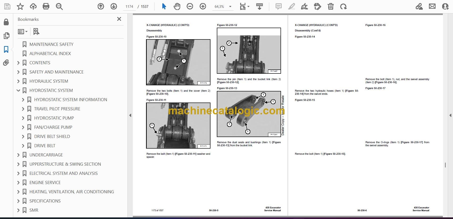
- X-CHANGE (HYDRAULIC)
- Removal And Installation
- Parts Identification
- Disassembly
- Assembly
- COUNTERWEIGHT
- ELECTRICAL SYSTEM AND ANALYSIS
- ELECTRICAL SCHEMATICS
- ELECTRICAL SYSTEM INFORMATION
- Troubleshooting Chart
- Description
- Fuse And Relay Location
- BATTERY
- Servicing
- Removing And Installing The Battery
- Using A Booster Battery (Jump Starting)
- ALTERNATOR
- Engine Accessory Drive Belt
- Removal And Installation
- Alternator Identification
- Charging System Check
- Alternator Voltage Test
- Low Voltage Test
- High Voltage Test
- Rectifier Continuity (Diode) Test
- Alternator Regulator Test
- Parts Identification
- Disassembly
- Stator Continuity Test
- Stator Ground Test
- Rotor Continuity Test
- Rotor Ground Test
- Assembly
- STARTER
- Removal And Installation
- Parts Identification
- Disassembly
- Inspection And Repair
- Assembly
- LIGHTS
- Removal And Installation
- Boom Light Removal and Installation (Earlier Models)
- Boom Light Removal and Installation (Later Models)
- Boom Light Bulb Replacement (Later Models)
- TWO SPEED SWITCH
- FUEL LEVEL SENDER
- Removal And Installation
- Testing
- DIAGNOSTICS SERVICE CODE
- DELUXE INSTRUMENT PANEL SETUP
- Passwords
- Password Entry (For Starting and Operating the Machine)
- Changing The Owner or Operator Password
- Password Lockout Feature
- Job Clock
- RPM
- ENGINE SERVICE
- TROUBLESHOOTING
- MUFFLER
- AIR CLEANER
- RADIATOR
- ENGINE COMPONENTS & TESTING (S/N 562611001 & ABOVE)
- Engine Compression Checking
- Glow Plug Removal And Installation
- Checking The Glow Plug
- Fuel Shut-off Solenoid Removal And Installation
- Fuel Injection Pump Check
- Fuel Injection Pump Removal And Installation
- Fuel Injection Pump Timing
- Fuel Injector Nozzles Removal And Installation
- Fuel Injector Nozzle Check
- Valve Clearance Adjustment
- ENGINE COMPONENTS & TESTING (S/N 562811001 & ABOVE, 563111001 & ABOVE AND 563211001 & ABOVE)
- Engine Compression Checking
- Glow Plug Removal And Installation
- Checking The Glow Plug
- Fuel Shut-off Solenoid Removal And Installation
- Fuel Injection Pump Check
- Fuel Injection Pump Removal And Installation
- Fuel Injection Pump Timing
- Fuel Injector Nozzles Removal And Installation
- Fuel Injector Nozzle Check
- Valve Clearance Adjustment
- ENGINE
- ENGINE FLYWHEEL (EARLY MODELS)
- Removal And Installation
- Hydraulic Pump Coupler
- Flywheel Ring Gear
- ENGINE FLYWHEEL (LATER MODELS)
- Removal And Installation
- Hydraulic Pump Coupler
- Flywheel Ring Gear
- RECONDITIONING THE ENGINE (S/N 562611001 AND ABOVE)
- Cylinder Head Removal And Installation
- Cylinder Head Disassembly And Assembly
- Cylinder Head Servicing
- Cylinder Head Top Clearance
- Valve Guide Checking
- Reconditioning The Valve And Valve Seat
- Valve Spring
- Rocker Arm And Shaft Checking
- Timing Gearcase Cover Removal And Installation
- Idler Gear And Camshaft Removal And Installation
- Camshaft Servicing
- Idler Gear And Shaft Servicing
- Timing Gears Checking Backlash
- Fuel Camshaft Removal And Installation
- Fuel Camshaft Governor
- Crankshaft Gear Removal And Installation
- Oil Pump Removal And Installation
- Oil Pump Service
- Checking Engine Oil Pressure
- Relief Valve
- Piston And Connecting Rod Removal And Installation
- Piston And Connecting Rod Servicing
- Connecting Rod Alignment
- Crankshaft And Bearings Removal And Installation
- Crankshaft And Bearings Servicing
- Cylinder Bore Checking
- Water Pump Removal And Installation
- Water Pump Disassembly And Assembly
- RECONDITIONING THE ENGINE (S/N 562811001 & ABOVE, 563111001 & ABOVE AND 563211001 & ABOVE)
- Cylinder Head Removal And Installation
- Cylinder Head Disassembly And Assembly
- Cylinder Head Servicing
- Cylinder Head Top Clearance
- Valve Guide Checking
- Reconditioning The Valve And Valve Seat
- Valve Spring
- Rocker Arm And Shaft Checking
- Timing Gearcase Cover Removal And Installation
- Idler Gear And Camshaft Removal And Installation
- Camshaft Servicing
- Idler Gear And Shaft Servicing
- Timing Gears Checking Backlash
- Fuel Camshaft Removal And Installation
- Fuel Camshaft Governor
- Crankshaft Gear Removal And Installation
- Oil Pump Removal And Installation
- Oil Pump Service
- Checking Engine Oil Pressure
- Valve Tappets
- Piston And Connecting Rod Removal And Installation
- Piston And Connecting Rod Servicing
- Connecting Rod Alignment
- Crankshaft And Bearings Removal And Installation
- Crankshaft And Bearings Servicing
- Cylinder Bore Checking
- Water Pump Removal And Installation
- Water Pump Disassembly And Assembly
- HEATING, VENTILATION, AIR CONDITIONING
- HEATER COIL (EARLY MODELS)
- HEATER COIL (LATER MODELS)
- Removal And Installation With A/C
- Removal And Installation Without A/C
- BLOWER FAN (EARLY MODELS)
- Removal And Installation
- Disassembly And Assembly
- BLOWER FAN (LATER MODELS)
- Removal And Installation
- Disassembly And Assembly
- Resistor Removal And Installation
- HEATER VALVE
- AIR CONDITIONING SYSTEM FLOW
- COMPONENTS
- SAFETY
- REGULAR MAINTENANCE
- Heater Air Filter
- Engine Accessory Drive Belt
- Cleaning The Condenser
- BASIC TROUBLESHOOTING (EARLY MODELS)
- Poor A/C Performance
- Cleaning The A/C Evaporator Coil & Heater Coil
- Engine Accessory Drive Belt
- Checking The Electrical System
- Engine Coolant By-Passing The Heater Valve
- BASIC TROUBLESHOOTING (LATER MODELS)
- Poor A/C Performance
- Cleaning The A/C Evaporator Coil & Heater Coil
- Engine Accessory Drive Belt
- Checking The Electrical System
- Engine Coolant By-Passing The Heater Valve
- GENERAL AIR CONDITIONING SERVICE GUIDELINES
- Compressor Oil
- Compressor Oil Check
- Component Replacement And Refrigeration Leaks
- SYSTEM TROUBLESHOOTING CHART
- Blower Motor Does Not Operate
- Gauge Pressure Related Troubleshooting
- TEMPERATURE/PRESSURE
- AIR CONDITIONING SERVICE
- SYSTEM CHARGING AND RECLAMATION
- Reclamation Procedure
- Charging Procedure With A Manifold Gauge Set
- COMPRESSOR
- Removal And Installation
- Compressor Clutch Disassembly And Assembly
- CONDENSER
- RECEIVER/DRIER
- PRESSURE RELIEF VALVE
- PRESSURE SWITCH
- EVAPORATOR/HEATER UNIT (EARLY MODELS)
- Removal And Installation
- Disassembly And Assembly
- EVAPORATOR/HEATER UNIT (later MODELS)
- Removal And Installation
- Disassembly And Assembly
- THERMOSTAT (EARLY MODELS)
- THERMOSTAT (LATER MODELS)
- EXPANSION VALVE (EARLY MODELS)
- EXPANSION VALVE (LATER MODELS)
- EVAPORATOR (EARLY MODELS)
- EVAPORATOR (LATER MODELS)
- SPECIFICATIONS
- SPECIFICATIONS
- Excavator Machine Dimensions
- Performance (S/N 562611001 & Above, 562811001 & Above And 563211001 & Above)
- Performance (S/N 563111001 & Above)
- Controls
- Engine
- Hydraulic System
- Hydraulic Cylinders
- Hydraulic Cycle Times
- Drive System (S/N 562611001 & Above, 562811001 & Above And 563211001 & Above)
- Drive System (S/N 563111001 & Above)
- Undercarriage
- Track (S/N 562611001 & Above And 562811001 & Above)
- Track (S/N 563111001 & Above And 563211001 & Above)
- Electrical
- ENGINE SPECIFICATIONS (S/N 562611001 & ABOVE)
- Fuel Injection Nozzles
- Fuel Injection Pump
- Cylinder Head
- Valves
- Valve Springs
- Valve Timing
- Rocker Arms
- Camshaft
- Tappet
- Cylinders
- Piston Rings
- Pistons
- Connecting Rods
- Oil Pump
- Crankshaft
- Timing Gear
- Thermostat
- Engine Bolt Torque
- Crankshaft Re-Grind Data
- ENGINE SPECIFICATIONS (S/N 562811001 & ABOVE, 563111001 & ABOVE AND 563211001 & ABOVE)
- Fuel Injection Nozzles
- Fuel Injection Pump
- Cylinder Head
- Valves
- Valve Springs
- Valve Timing
- Rocker Arms
- Camshaft
- Tappet
- Cylinders
- Piston Rings
- Pistons
- Connecting Rods
- Oil Pump
- Crankshaft
- Timing Gear
- Thermostat
- Engine Bolt Torque
- Crankshaft Re-Grind Data
- TORQUE SPECIFICATIONS
- Torque for General SAE Bolts
- Torque For General Metric Bolts
- HYDRAULIC CONNECTION SPECIFICATIONS
- O-Ring Face Seal Connection
- Straight Thread O-ring Fitting
- Tubelines And Hoses
- Flare Fitting
- O-Ring Flare Fitting
- Port Seal Fitting
- HYDRAULIC FLUID SPECIFICATIONS
- FUEL, COOLANT AND LUBRICANTS
- CONVERSIONS
- Decimal And Millimeter Equivalents
- U.S. To Metric Conversion Chart
- SMR
- 435-1
- 435-2
- 435-3
- 435-4
- 435-5
- 435-6
- 435-7
- 435-8
- 435-9
- 435-10
- 435-11
- 435-12
Bobcat Software
Bobcat PDF Manuals


