The V638 VersaHANDLER TTC is a telescopic handler that spends its life loading trucks, stacking pallets, and running forks or buckets around farms and jobsites. The people who reach for this service manual are the ones actually keeping it moving: shop mechanics, field techs, and owner-operators who are done guessing. They want wiring schematics that are readable, hydraulic test points called out, and step-by-step teardown info so a repair only happens once. If that sounds like your day, this is the type of book you're looking at.
What this manual helps you do
- Diagnose hydraulic issues by checking pressures, test ports, and valve logic on the boom and stabilizer circuits
- Trace and troubleshoot electrical faults using wiring diagrams for lights, safety interlocks, and controls
- Follow teardown and reassembly procedures for the boom, cylinders, axles, steering, and driveline components
- Set and verify adjustments on linkages, brakes, boom sections, and attachment couplers so they're in spec
- Replace major components like pumps, motors, and engine accessories with the right sequences and torque references
Who this is for
This manual is for anyone maintaining or repairing a Bobcat V638 VersaHANDLER TTC in the A8HM11001-A8HM99999 serial range: small contractors, farm shops, rental fleets, and field techs. If you only need basic operating instructions or daily checks, you want the operator's handbook instead, not this service manual.
FAQ
Q: Is this a searchable PDF and are the wiring diagrams readable?
A: Yes, these manuals are typically in searchable PDF format and the wiring diagrams are designed to be zoomed in on-screen without losing clarity.
Q: How do I know if it fits my exact machine?
A: If your telehandler is a Bobcat V638 VersaHANDLER TTC with a serial number between A8HM11001 and A8HM99999, this is the correct service manual range.
Q: Is this what I need for real repairs, not just maintenance checklists?
A: Yes, this is the workshop-level service manual used for diagnostics, teardown, and repair, not the operator's or parts manual.
Bottom line: If your V638's serial number falls in that A8HM range and you're doing your own repairs or running a shop, this is the right manual. If you just want to learn how to drive it, skip this and get the operator's book.
📘 Show Index
Table of Contents:
- CONTENTS
- FOREWORD
- FOREWORD
- SAFETY INSTRUCTIONS
- FIRE PREVENTION
- Maintenance
- Operation
- Electrical
- Hydraulic System
- Fueling
- Starting
- Spark Arrester Exhaust System
- Welding And Grinding
- Fire Extinguishers
- SERIAL NUMBER LOCATION
- VersaHANDLER Serial Number
- Engine Serial Number
- Other Serial Numbers
- DELIVERY REPORT
- BOBCAT VersaHANDLER IDENTIFICATION
- SAFETY & MAINTENANCE
- LIFTING AND BLOCKING THE VERSAHANDLER
- OPERATOR CAB / CANOPY
- TRANSPORTING THE VERSAHANDLER ON A TRAILER
- Loading And Unloading
- Fastening
- TOWING THE VersaHANDLER
- SERVICE SCHEDULE
- AIR CLEANER SERVICE
- Replacing Filter Element(s)
- ENGINE COOLING SYSTEM
- Cleaning The Cooling System
- Checking The Coolant Level
- Replacing The Coolant
- FUEL SYSTEM
- Fuel Specifications
- Filling The Fuel Tank
- Fuel Filter
- ENGINE LUBRICATION SYSTEM
- Checking Engine Oil
- Engine Oil Chart
- Replacing Oil And Filter
- HYDRAULIC / HYDROSTATIC SYSTEM
- Checking And Adding Fluid
- Replacing Hydraulic / Hydrostatic Filter
- Replacing Hydraulic Fluid
- AXLES (FRONT AND REAR)
- Checking Oil Level (Planetary Carrier)
- Draining Oil (Planetary Carrier)
- Checking Oil Level (Rear Differential)
- Draining Oil (Rear Differential)
- Checking Oil Level (Front Differential)
- Draining Oil (Front Differential)
- LUBRICATION
- ATTACHMENT FRAME
- Inspection And Maintenance
- TIRE MAINTENANCE
- Wheel Nuts
- Mounting
- Rotating
- SPARK ARRESTER MUFFLER
- APPROVED BOOM STOP
- Installing The Approved Boom Stop
- Removing The Approved Boom Stop
- ENGINE COVER
- Opening And Closing The Engine Cover
- LATERAL OPERATOR RESTRAINT SYSTEM (LORS)
- System Inspection
- Maintaining
- CHAIN
- Checking And Adjustment Procedure
- Extend / Retract Chain Wear Check
- STOPPING THE ENGINE AND LEAVING THE VERSAHANDLER
- VersaHANDLER STORAGE AND RETURN TO SERVICE
- Storage
- Return To Service
- EMERGENCY EXIT
- HYDRAULIC SYSTEM
- HYDRAULIC / HYDROSTATIC SCHEMATICS
- HYDRAULIC SYSTEM INFORMATION
- Glossary Of Hydraulic / Hydrostatic Symbols
- Troubleshooting Chart
- Tightening Procedures
- LIFT CYLINDER
- Removal And Installation
- Parts Identification
- Disassembly
- Assembly
- BUCKET POSITION CYLINDER
- Removal And Installation
- Removal And Installation (Cont’d)
- Parts Identification
- Disassembly
- Assembly
- EXTENSION CYLINDER
- Cylinder Group Removal And Installation
- Parts Identification
- Disassembly
- Assembly
- TILT CYLINDER
- Removal And Installation
- Parts Identification
- Disassembly
- Assembly
- STEERING CYLINDER (FRONT)
- Removal
- Installation
- Disassembly
- Assembly
- STEERING CYLINDER (REAR)
- Removal
- Installation
- Disassembly
- Assembly
- DRIVE BOX
- Parts Identification
- Disassembly
- Assembly
- Special Tools
- MAIN RELIEF VALVE
- Testing And Adjustment
- Removal And Installation
- QUICK-TACH CYLINDER
- Removal And Installation
- Parts Identification
- Disassembly
- Assembly
- FRAME LEVELING CYLINDER
- Removal And Installation
- Parts Identification
- Disassembly
- Assembly
- STEERING MODE VALVE BLOCK
- Removal And Installation
- Parts Identification
- Disassembly
- Solenoid Testing
- Assembly
- BRAKE VALVE
- Removal And Installation
- Disassembly And Assembly
- GEAR PUMP
- Removal And Installation
- Parts Identification
- Disassembly And Assembly
- FAN MOTOR
- Removal And Installation
- Parts Identification
- Disassembly And Assembly
- HYDRAULIC RESERVOIR
- STEERING VALVE
- Removal And Installation
- Parts Identification
- Disassembly
- Inspection
- Assembly
- HYDRAULIC CONTROL VALVE
- Troubleshooting Chart (Controllers)
- Telescoping Valve Section Troubleshooting
- Auxiliary Valve Section Troubleshooting
- Troubleshooting Chart (Control Valve)
- Removal And Installation
- Parts Identification
- Disassembly And Assembly
- End Housing Disassembly And Assembly
- Lifting Valve Section Disassembly And Assembly
- Tilting Valve Section Disassembly And Assembly
- Telescoping Valve Section Disassembly And Assembly
- Auxiliary / Frame Leveling Valve Section Disassembly And Assembly
- Inlet-Outlet Valve Section Disassembly And Assembly
- PORT RELIEF VALVES
- FLOW CONTROL VALVE
- JOYSTICK
- PARKING BRAKE
- Pressure Switch Removal And Installation
- Pressure Switch Disassembly And Assembly
- Parking Brake Valve Removal And Installation
- Parking Brake Valve Disassembly And Assembly
- PRESSURE REDUCING VALVE
- Testing
- Removal And Installation
- Disassembly And Assembly
- ACCUMULATOR
- TOW VALVE
- Removal And Installation
- Disassembly And Assembly
- STABILIZER CYLINDER
- Removal
- Parts Identification
- Disassembly
- Assembly
- Installation
- STABILIZER CONTROL VALVE
- Parts Identification
- Removal
- Installation
- HYDROSTATIC SYSTEM
- HYDROSTATIC SYSTEM INFORMATION
- Troubleshooting Chart
- Replenishing Valve Function
- OIL COOLER
- HYDROSTATIC DRIVE MOTOR
- Removal And Installation
- Parts Identification
- Disassembly
- Inspection
- Assembly
- HYDROSTATIC PUMP
- Removal And Installation
- Parts Identification
- Disassembly
- Inspection
- Assembly
- DRIVE SYSTEM
- TROUBLESHOOTING
- AXLE AND DIFFERENTIAL (FRONT)
- General Information
- Planetary Carrier Parts Identification
- Planetary Carrier Disassembly
- Steering Knuckle And Drive Axle Parts Identification
- Steering Knuckle Disassembly
- Drive Axle Disassembly
- Brake System Parts Identification
- Brake System Disassembly
- Differential Parts Identification
- Differential Disassembly
- Bevel Pinion Parts Identification
- Bevel Pinion Disassembly
- Bevel Pinion Assembly
- Differential Assembly
- Brake System Assembly
- Drive Axle Assembly
- Steering Knuckle Assembly
- Planetary Carrier Assembly
- Special Tools
- AXLE AND DIFFERENTIAL (REAR)
- General Information
- Planetary Carrier Parts Identification
- Steering Knuckle And Drive Axle Parts Identification
- Steering Knuckle Disassembly
- Differential And Bevel Pinion Parts Identification
- Differential Disassembly
- Bevel Pinion Disassembly
- Bevel Pinion Assembly
- Differential Assembly
- Steering Knuckle Assembly
- Planetary Carrier Assembly
- Special Tools
- FRONT AXLE
- AXLE TOE-IN
- PARKING BRAKE
- Releasing The Brake For Towing
- Re-Activating The Brake
- STEERING ANGLE ADJUSTMENT
- DRIVE SHAFT
- SERVICE BRAKE
- Description
- Bleeding The Brake Circuit
- REAR AXLE
- MAINFRAME
- OPERATOR CAB (S/N A8HM12999 & BELOW)
- OPERATOR CAB (S/N A8HM13000 & ABOVE)
- CANOPY
- OPERATOR SEAT
- FIXED BOOM
- END BOOM
- WEAR PADS (FRONT)
- WEAR PADS (REAR)
- ENGINE COVER
- Gas Cylinder Removal And Installation
- Removal And Installation
- AIR INTAKE COWLING
- FUEL TANK
- QUICK-TACH
- REAR WEIGHTS
- FENDER
- PIVOT LINK
- DASH COVER / STEERING COLUMN COVER (S/N A8HM12999 & BELOW, S/N A8HN12999 & BELOW)
- DASH COVER / STEERING COLUMN COVER (S/N A8HM13000 & ABOVE, S/N A8HN13000 & ABOVE)
- JOYSTICK PANEL (S/N A8HM12999 & BELOW, S/N A8HN12999 & BELOW)
- JOYSTICK PANEL (S/N A8HM13000 & ABOVE, S/N A8HN13000 & ABOVE)
- INTERMEDIATE BOOM
- BOOM TRAY
- STABILIZER FRAME
- ELECTRICAL SYSTEM & ANALYSIS
- ELECTRICAL SCHEMATICS
- ELECTRICAL SYSTEM INFORMATION (S/N A8HM12999 & BELOW, S/N A8HN12999 & BELOW)
- Troubleshooting Chart
- Description
- Fuses, Diodes And Relays
- ELECTRICAL SYSTEM INFORMATION (S/N A8HM13000 & ABOVE, S/N A8HN13000 & ABOVE)
- Troubleshooting Chart
- Description
- Fuses, Diodes And Relays
- BATTERY
- Removal And Installation
- Servicing
- Using A Booster Battery (Jump Starting)
- ALTERNATOR
- Removal And Installation
- Adjusting The Alternator Belt
- STARTER
- Removal And Installation
- Parts Identification
- Disassembly
- Inspection And Repair
- Assembly
- LATERAL OPERATOR RESTRAINT SYSTEM (LORS)
- Restraint Bar Removal And Installation
- Sensor Removal And Installation
- Strut Removal And Installation
- Strut Disassembly And Assembly
- Restraint Bar Bushing Removal And Installation
- Restraint Bar Bumper Removal And Installation
- LIGHTS
- Rear Light Removal And Installation
- Front Light Removal And Installation
- TRAVEL / SIGNAL LEVER (S/N A8HM12999 & BELOW, S/N A8HN12999 & BELOW)
- TRAVEL / SIGNAL LEVER (S/N A8HM13000 & ABOVE, S/N A8HN13000 & ABOVE)
- INSTRUMENT PANEL
- SWITCH PANEL (S/N A8HM12999 & BELOW, S/N A8HN12999 & BELOW)
- Removal And Installation
- Parts Identification
- SWITCH PANEL (S/N A8HM13000 & ABOVE, S/N A8HN13000 & ABOVE)
- Removal And Installation
- Parts Identification
- BRAKE LIGHT SWITCH
- Removal And Installation
- Adjustment
- WIPER MOTOR (FRONT)
- WIPER MOTOR (TOP)
- WIPER MOTOR (REAR)
- PEDAL ASSEMBLY
- Removal And Installation
- Disassembly And Assembly
- INCHING SWITCH
- Removal And Installation
- Adjustment
- SERVICE SOFTWARE
- Connecting The Laptop Computer
- Entering The Service Software
- Monitor Screen
- Warnings Screen
- Calibrate Inch Pedal
- Calibrate Creep Potentiometer
- Program / Update Susmic Controller
- FRAME LEVEL SPEED SWITCH
- Description
- Removal
- Installation
- ENGINE SERVICE
- TROUBLESHOOTING
- ENGINE SPEED CONTROL
- MUFFLER
- AIR CLEANER
- Housing Removal And Installation
- OIL COOLER / RADIATOR
- Removal And Installation
- Disassembly And Assembly
- ENGINE AND ENGINE MOUNTS
- ENGINE COMPONENTS AND TESTING
- Fuel Injection Pump Removal
- Fuel Injection Pump Installation
- Fuel Injector Removal And Installation
- Checking The Fuel Lift Pump
- Fuel Lift Pump Removal And Installation
- Compression Checking
- Glow Plug Checking
- Glow Plugs Removal And Installation
- ENGINE TIMING
- ENGINE / HYDROSTAT ASSEMBLY
- FLYWHEEL AND HOUSING
- Removal And Installation
- Ring Gear Removal
- Ring Gear Installation
- RECONDITIONING THE ENGINE
- Turbocharger Troubleshooting
- Turbocharger Description
- Turbocharger Removal And Installation
- Exhaust Manifold Removal And Installation
- Fuel Injector Cover Removal And Installation
- Rocker Cover Removal And Installation
- Cylinder Head Removal
- Cylinder Head Inspection
- Cylinder Head Installation
- Rocker Shaft Disassembly And Assembly
- Valve Removal
- Valve Springs Checking
- Valve Depth Checking
- Valve Guides Checking
- Valve Guide Removal
- Valve Guide Installation
- Valves Checking
- Cutting A Valve Seat
- Valve Seat Assembly
- Changing Valve Springs (With Cylinder Head Installed)
- Valve Clearance Adjustment
- Timing Case And Drive Assembly Description
- Timing Cover Removal
- Timing Cover Installation
- Crankshaft Pulley Removal And Installation
- Front Oil Seal Removal And Installation
- Timing Case And Gear Removal
- Timing Case And Gear Installation
- Camshaft And Tappets Removal
- Camshaft And Tappets Installation
- Pistons And Connecting Rods Description
- Pistons And Connecting Rods Removal
- Pistons And Connecting Rods Disassembly
- Piston Ring End Gap
- Piston Ring Installation
- Piston Ring Groove Clearance
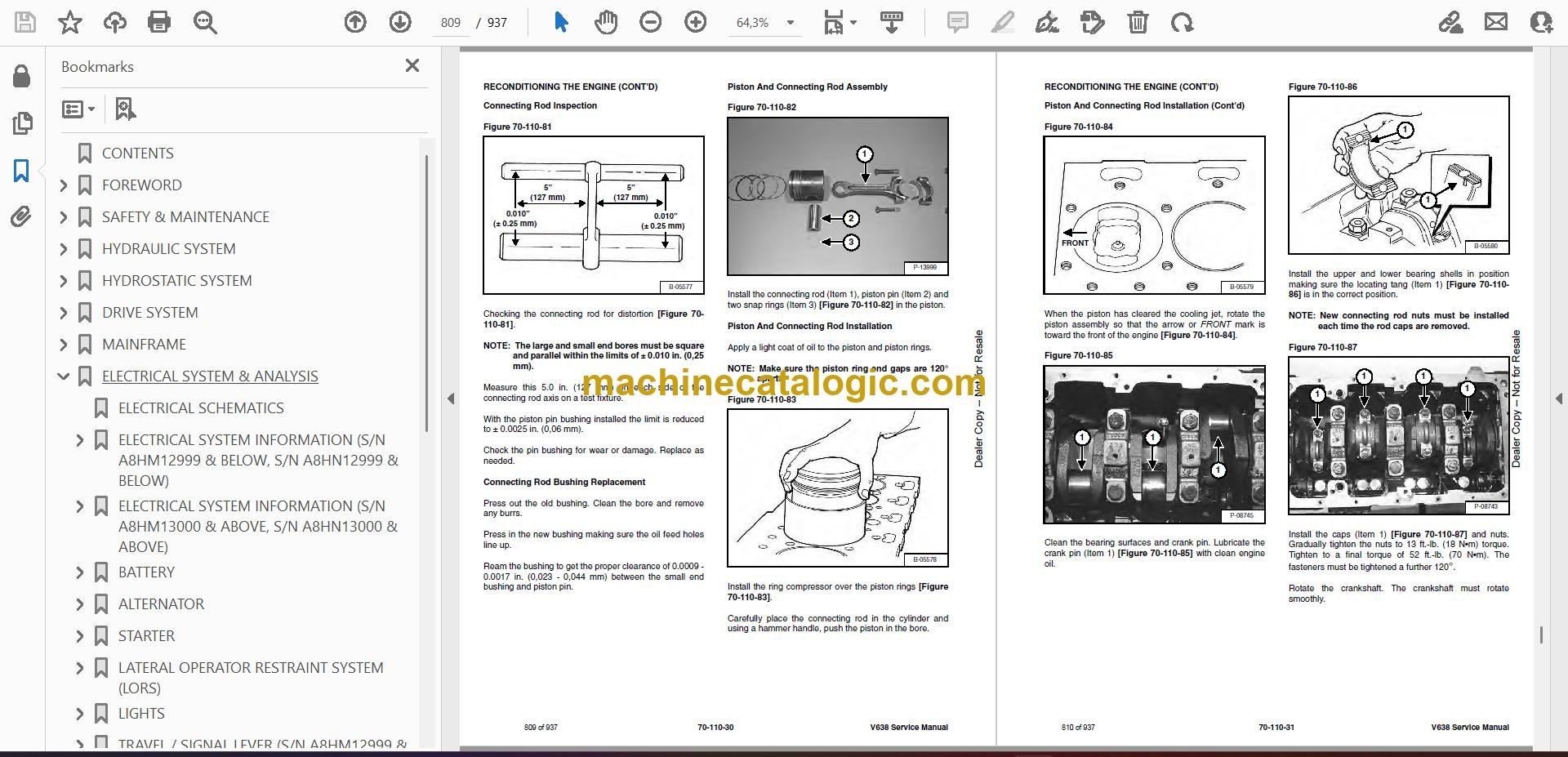
- Connecting Rod Inspection
- Connecting Rod Bushing Replacement
- Piston And Connecting Rod Assembly
- Piston And Connecting Rod Installation
- Checking Piston Height
- Crankshaft And Bearings Description
- Crankshaft And Bearings Removal
- Inspection Of Crankshaft And Bearings
- Crankshaft And Bearings Installation
- Rear Oil Seal Removal
- Rear Oil Seal Housing Positioning
- Rear Oil Seal Installation
- Checking Crankshaft End Play
- Cooling System Description
- Thermostat Removal and Installation
- Thermostat Testing
- Lubricating Oil Cooler Removal And Installation
- Water Pump Removal
- Water Pump Installation
- Engine Lubrication System Description
- Oil Filter Adapter Removal And Installation
- Oil Pan Removal And Installation
- Oil Screen And Pick-up Tube
- Oil Pump Removal
- Oil Pump Installation
- Oil Pump Disassembly And Assembly
- Oil Pressure Relief Valve Disassembly And Assembly
- Engine Block Description
- Engine Block Disassembly And Assembly
- Piston Cooling Jet Removal
- Piston Cooling Jet Installation
- Piston Cooling Jet Alignment
- Inspection
- Cylinder Liner Inspection
- Cylinder Liner Removal
- Cylinder Liner Installation
- HEATING, VENTILATION AND AIR CONDITIONING (HVAC)
- AIR CONDITIONING SYSTEM FLOW
- COMPONENTS
- SAFETY
- REGULAR MAINTENANCE
- Filter Element Removal And Installation
- Compressor Drive Belt Inspection
- Cleaning The Condenser
- BASIC TROUBLESHOOTING
- Poor A/C Performance
- Compressor Drive Belt Inspection
- Checking The Electrical System
- GENERAL AIR CONDITIONING SERVICE GUIDELINES
- Compressor Oil
- Compressor Oil Check
- Component Replacement And Refrigeration Leaks
- SYSTEM TROUBLESHOOTING
- Chart
- Gauge Pressure Related Troubleshooting
- TEMPERATURE / PRESSURE
- AIR CONDITIONING SERVICE
- SYSTEM CHARGING AND RECLAMATION
- Reclamation Procedure
- Charging Procedure With A Manifold Gauge Set
- Charging Procedure
- COMPRESSOR
- Removal And Installation
- Compressor Clutch Disassembly And Assembly
- CONDENSER (S/N A8HM12999 & BELOW)
- CONDENSER (S/N A8HM13000 & ABOVE)
- RECEIVER / DRIER
- PRESSURE SWITCH
- EVAPORATOR / BLOWER UNIT (S/N A8HM12999 & BELOW)
- EVAPORATOR / BLOWER / HEATER UNIT (S/N A8HM13000 & ABOVE)
- EXPANSION VALVE (S/N A8HM12999 & BELOW)
- EXPANSION VALVE (S/N A8HM13000 & ABOVE)
- HEATER ASSEMBLY
- Removal And Installation
- Fan Removal And Installation
- Core Removal And Installation
- SPECIFICATIONS
- VERSAHANDLER SPECIFICATIONS
- Machine Dimensions
- Performance Specifications
- Engine
- Controls
- Drive System
- Tires
- Capacities
- Hydraulic System
- Electrical
- Instrument Panel
- ENGINE SPECIFICATIONS
- General
- Cylinder Head
- Valve Guides
- Exhaust Valves
- Intake Valves
- Valve Springs
- Rocker Shaft, Rockers And Bushings
- Pistons And Piston Rings
- Connecting Rods And Bearings
- Crankshaft
- Crankshaft Re-Grind Data
- Main Bearings
- Thrust Washers
- Camshaft And Thrust Washer
- Cylinder Block
- Cylinder Liners
- Fuel Injection Pump
- Fuel Injectors
- Fuel Lift Pump
- Timing Case And Timing Gears
- Oil Pump, Gear And Relief Valve
- Turbocharger
- Flywheel
- Water Pump And Thermostat
- Engine Torque Component
- MACHINE TORQUE SPECIFICATIONS
- Axle
- Boom
- Drive Box
- Drive Motor
- Engine
- Hydraulic Pump
- TORQUE SPECIFICATIONS FOR BOLTS
- Torque for General SAE Bolts
- Torque For General Metric Bolts
- HYDRAULIC CONNECTION SPECIFICATIONS
- O-ring Face Seal Connection
- Straight Thread O-ring Fitting
- Tubelines And Hoses
- Port Seal Fitting
- HYDRAULIC / HYDROSTATIC FLUID SPECIFICATIONS
- CONVERSIONS
- Decimal And Millimeter Equivalent Chart
- U.S. To Metric Conversion Chart
- ALPHABETICAL INDEX
- SERVICE MANUAL REVISION
Bobcat Software
Bobcat PDF Manuals


