Format: PDF (Printable Document)
File Language: English
File Pages: 713
File Size: 29.25 MB (Speed Download Link)
Brand: BT
Model: C15, VCE150A, 150AC, VCE125ASF, 125ASFC
Part No: 227761-040
Type of Document: Repair Manual
$ 40
1. Table of content
2. General introduction…………………………………………………………………………… 2-1
2.1 Warning symbols ……………………………………………………………………………… 2-1
2.2 Pictograms………………………………………………………………………………………. 2-1
2.2.1 Repairable …………………………………………………………………………… 2-1
2.2.2 Other pictograms………………………………………………………………….. 2-2
3. P2 (T code 712) – C15, VCE150…………………………………………………………….. 3-1
3.1 Preventive maintenance – Maintenance schedule ………………………………… 3-1
3.2 Correct inspection procedure …………………………………………………………….. 3-7
4. P2 (T code 713) – VCE125 ……………………………………………………………………. 4-1
4.1 Preventive maintenance – Maintenance schedule ………………………………… 4-1
4.2 Correct inspection procedure …………………………………………………………….. 4-5
5. P3 (T code 712) – C15, VCE150…………………………………………………………….. 5-1
5.1 Oil and grease specifications……………………………………………………………… 5-1
6. P3 (T code 713) – VCE125 …………………………………………………………………… 6-1
6.1 Oil and grease specification – ……………………………………………………………. 6-1
7. Tools – P4 ………………………………………………………………………………………….. 7-1
7.1 Super Seal contact …………………………………………………………………………… 7-1
7.1.1 AMP connectors …………………………………………………………………… 7-2
7.1.2 Miscellaneous tools ………………………………………………………………. 7-3
8. Chassis – 0000 Truck installation……………………………………………………….. 8-1
8.1 General…………………………………………………………………………………………… 8-1
8.2 Tool list …………………………………………………………………………………………… 8-1
8.3 Unloading the truck…………………………………………………………………………… 8-2
8.3.1 Unloading a standing truck…………………………………………………….. 8-2
Drive the truck off the trailer 8-2
Towing the truck off the trailer 8-3
Unloading with a counterweight truck 8-4
8.3.2 Unloading a truck lying down …………………………………………………. 8-5
Unloading the truck from a lorry using a counter balance truck 8-6
8.3.3 Unloading the truck using cranes ……………………………………………. 8-7
8.3.4 Erecting the truck …………………………………………………………………. 8-9
8.3.5 Final assembly …………………………………………………………………… 8-14
8.3.6 Assembly of the initial mast………………………………………………….. 8-14
8.4 Preparations for commissioning ……………………………………………………….. 8-15
8.5 Installation in narrow aisle ……………………………………………………………….. 8-15
8.5.1 General……………………………………………………………………………… 8-15
8.5.2 Rail-guided truck ………………………………………………………………… 8-16
8.5.3 Wire-guided truck ……………………………………………………………….. 8-16
8.5.4 Support arm collision guards………………………………………………… 8-17
Assembling the guards during truck installation 8-17
9. Frame pivot – 0320……………………………………………………………………………… 9-1
9.1 Removal/reassembly of rear chassis, including bearings……………………….. 9-1
9.1.1 Special tools ………………………………………………………………………… 9-1
9.1.2 Standard hand tools ……………………………………………………………… 9-1
9.1.3 Disassembly ………………………………………………………………………… 9-2
Jack up the truck to prepare for disassembly 9-2
Disassembly of components 9-8
9.1.4 Dismantle the rear chassis …………………………………………………… 9-13
9.2 Replacing the bearing frame links …………………………………………………….. 9-14
9.2.1 Remove the old bearings …………………………………………………….. 9-14
9.2.2 Install new bearings…………………………………………………………….. 9-15
9.2.3 Reinstall the rear chassis …………………………………………………….. 9-18
9.2.4 Reassemble the truck………………………………………………………….. 9-19
9.2.5 Lower the truck to the ground……………………………………………….. 9-20
9.2.6 Final assembly …………………………………………………………………… 9-20
10. General tightening torque – 0400 …………………………………………………….. 10-1
10.1 Galvanised, non-oiled bolts ……………………………………………………………. 10-1
10.2 Untreated, lubricated bolts……………………………………………………………… 10-1
10.3 Tightening torques………………………………………………………………………… 10-2
11. Electric AC pump motor – 1710.1 …………………………………………………….. 11-1
11.1 General……………………………………………………………………………………….. 11-1
11.2 Disassembled pump motor…………………………………………………………….. 11-1
11.3 Disassembly and assembly of the pump motor…………………………………. 11-2
11.3.1 Disassembly …………………………………………………………………….. 11-3
11.3.2 Installation ……………………………………………………………………….. 11-3
11.4 Replacing the ball bearing ……………………………………………………………… 11-4
11.4.1 Disassembly …………………………………………………………………….. 11-4
11.4.2 Installation ……………………………………………………………………….. 11-5
11.5 Assembly instruction for the external temperature sensor ………………….. 11-6
12. Electric DC pump motor – 1710.2 …………………………………………………….. 12-1
12.1 General……………………………………………………………………………………….. 12-1
12.2 Disassembled pump motor…………………………………………………………….. 12-1
12.2.1 Connection ………………………………………………………………………. 12-1
12.3 Disassembly and assembly of the pump motor…………………………………. 12-2
12.3.1 Disassembly …………………………………………………………………….. 12-2
12.3.2 Installation ……………………………………………………………………….. 12-3
12.4 Replacing the ball bearing ……………………………………………………………… 12-4
12.4.1 Disassembly (D side) ………………………………………………………… 12-4
12.4.2 Installation ……………………………………………………………………….. 12-4
12.4.3 Disassembly (N side) ………………………………………………………… 12-5
12.4.4 Assembly (N side) …………………………………………………………….. 12-5
12.4.5 Carbon brushes and carbon brush-rocker…………………………….. 12-5
New carbon brushes must always be smoothed beforehand 12-5
Commutator 12-6
Truing the commutator 12-6
13. Electric drive motor – 1760 ……………………………………………………………… 13-1
13.1 General……………………………………………………………………………………….. 13-1
13.2 Disassembled drive motor ……………………………………………………………… 13-2
13.3 Disassembly and assembly of the drive motor ………………………………….. 13-3
13.3.1 Disassembly of the drive motor …………………………………………… 13-3
Disassemble the gear wheel 13-3
Disassemble the brake 13-3
13.3.2 Assembly of the drive motor……………………………………………….. 13-4
Assemble the brake 13-4
Assemble the gear wheel 13-4
13.4 Replacing the ball bearing ……………………………………………………………… 13-5
13.4.1 Disassembly …………………………………………………………………….. 13-5
N side 13-5
D side 13-5
13.4.2 Installation ……………………………………………………………………….. 13-6
N side 13-6
D side 13-6
13.5 Assembly instruction for the external temperature sensor ………………….. 13-7
© TMHE 1 – 3 T Code(s): 712, 713
Repair manual: Table of content Model(s): C15, VCE150A/150AC, VCE125ASF/125ASFC
Publication Number: 227761-040 Date: 2013-04-30 Valid from Serial Number: 745600FD
14. Drive unit/gear – 2550 ……………………………………………………………………… 14-1
14.1 General……………………………………………………………………………………….. 14-1
14.2 Components/data of the drive unit and gear …………………………………….. 14-1
14.2.1 Component identification……………………………………………………. 14-2
14.2.2 Technical data ………………………………………………………………….. 14-4
14.2.3 Dismantled gear ……………………………………………………………….. 14-4
14.3 Replacing the drive motor/drive gear……………………………………………….. 14-5
14.3.1 Dismantling of drive unit from truck ……………………………………… 14-5
14.3.2 Fitting the drive unit in truck ……………………………………………….. 14-5
14.3.3 Dismantling the drive motor and the gear …………………………….. 14-6
14.3.4 Fitting the drive motor and the gear …………………………………….. 14-6
14.4 Oil level check/replacement……………………………………………………………. 14-7
14.4.1 Checking/refilling the oil …………………………………………………….. 14-7
14.4.2 Oil change ……………………………………………………………………….. 14-7
14.5 Repairs ……………………………………………………………………………………….. 14-8
14.5.1 Replacing the drive axle jointing ring……………………………………. 14-9
14.5.2 Leakage from the top cover………………………………………………. 14-10
14.5.3 Leakage from the lower cover …………………………………………… 14-10
14.5.4 Replacing the wheel bolts ………………………………………………… 14-11
15. Brake system – 3100……………………………………………………………………….. 15-1
15.1 General……………………………………………………………………………………….. 15-1
15.2 Function description ……………………………………………………………………… 15-1
15.2.1 Releasing the accelerator pedal………………………………………….. 15-1
15.2.2 Travel direction selector …………………………………………………….. 15-1
15.2.3 Depressing the brake button ………………………………………………. 15-1
15.2.4 Parking brake …………………………………………………………………… 15-3
15.2.5 Emergency braking …………………………………………………………… 15-3
15.3 Electro-mechanical disc brake, drive motor………………………………………. 15-3
15.3.1 Maintenance schedule and maintenance measures ………………. 15-4
15.4 Replacing the brake unit and dismantling the brake unit for
friction disc replacement……………………………………………………………………….. 15-4
15.4.1 Replacing the brake unit…………………………………………………….. 15-5
15.4.2 Dismantling the brake unit/checking and/or replacing
the brake disc …………………………………………………………………………….. 15-6
15.4.3 Checking/adjusting brake force …………………………………………… 15-7
15.4.4 Clean ………………………………………………………………………………. 15-7
15.4.5 Checking the air gap …………………………………………………………. 15-7
15.4.6 Checking/adjusting brake force …………………………………………… 15-8
15.4.7 Wear……………………………………………………………………………….. 15-9
15.4.8 Troubleshooting………………………………………………………………… 15-9
15.5 Disc brake with multiple discs, support arms…………………………………… 15-10
15.5.1 Checking play/wear …………………………………………………………. 15-10
15.5.2 Disassembly …………………………………………………………………… 15-11
15.5.3 Inspection ………………………………………………………………………. 15-12
15.5.4 Installation ……………………………………………………………………… 15-12
15.5.5 Maintenance…………………………………………………………………… 15-12
15.5.6 Adjustment of play…………………………………………………………… 15-13
16. Wheels – 3500…………………………………………………………………………………. 16-1
16.1 Drive wheel – 3530……………………………………………………………………….. 16-1
16.1.1 General……………………………………………………………………………. 16-1
16.1.2 Disassemble the drive wheel………………………………………………. 16-1
16.1.3 Assembling the drive wheel………………………………………………… 16-1
16.1.4 Available wheel grades ……………………………………………………… 16-2
16.2 Support arm wheels – 3550……………………………………………………………. 16-2
16.2.1 Dismantling the wheel ……………………………………………………….. 16-2
16.2.2 Assembling the wheel ……………………………………………………….. 16-4
16.2.3 Dismantling/assembling the wheel bearings …………………………. 16-5
16.2.4 Support arm wheel axle……………………………………………………… 16-7
16.2.5 Available wheel grades ……………………………………………………… 16-7
17. Steering system – 4000 …………………………………………………………………… 17-1
17.1 General……………………………………………………………………………………….. 17-1
17.1.1 Steering components ………………………………………………………… 17-3
17.1.2 Hydraulic diagram, steering system …………………………………….. 17-4
17.2 Function description ……………………………………………………………………… 17-6
17.2.1 Electrical System………………………………………………………………. 17-6
Wire-guidance mode 17-8
17.2.2 Hydraulic system ………………………………………………………………. 17-9
17.2.3 Temperature and voltage compensation………………………………. 17-9
17.3 Troubleshooting………………………………………………………………………….. 17-10
17.3.1 Operations/repair, hydraulics ……………………………………………. 17-10
18. Steering cylinder – 4160…………………………………………………………………… 18-1
18.1 Instructions for checking for internal leaks ……………………………………….. 18-1
18.1.1 Check in conjunction with 2000-hour service ………………………… 18-1
18.1.2 If wear is suspected…………………………………………………………… 18-1
18.2 Recommended procedure ……………………………………………………………… 18-1
18.3 Corrective action…………………………………………………………………………… 18-3
18.3.1 Procedure………………………………………………………………………… 18-3
18.4 Removing the steering cylinder from the truck ………………………………….. 18-4
18.5 Installing the steering cylinder in the truck………………………………………… 18-6
19. Wire guidance system – 4500 ………………………………………………………….. 19-1
19.1 Wire guidance………………………………………………………………………………. 19-1
19.1.1 General……………………………………………………………………………. 19-1
Abbreviations 19-1
Definitions 19-2
19.2 Wire guidance components ……………………………………………………………. 19-3
19.3 Functional description, General………………………………………………………. 19-6
Narrow aisle type 19-7
19.3.1 Travel speeds…………………………………………………………………… 19-8
19.3.2 Function description ………………………………………………………… 19-10
Run mode 19-10
Wire guidance, state in Run mode 19-10
Automatic steering control 19-13
19.4 Best practice for adjusting wire guidance. ………………………………………. 19-17
19.4.1 Set-up procedure…………………………………………………………….. 19-17
Battery check 19-17
Check antenna heights. 19-17
Learn steering valves 19-17
Set the chassis straight and learn the pivot angle. 19-17
Check the waist pot voltage with TruckCom. 19-18
Learn wire guidance frequency 19-18
Learn the wire 19-18
Fine-adjustment of straight articulated centre 19-19
Battery setting 19-19
19.5 Parameters ………………………………………………………………………………… 19-20
19.5.1 General wire guidance parameters ……………………………………. 19-20
19.5.2 Learned calibration values, steering…………………………………… 19-20
19.5.3 Learned calibration data, wire guidance……………………………… 19-20
19.6 Warning and error codes ……………………………………………………………… 19-20
© TMHE 1 – 5 T Code(s): 712, 713
Repair manual: Table of content Model(s): C15, VCE150A/150AC, VCE125ASF/125ASFC
Publication Number: 227761-040 Date: 2013-04-30 Valid from Serial Number: 745600FD
20. Electrical system – 5000………………………………………………………………….. 20-1
20.1 General……………………………………………………………………………………….. 20-1
20.1.1 Terminology……………………………………………………………………… 20-3
20.1.2 Truck firmware applications………………………………………………… 20-3
20.1.3 Communication ………………………………………………………………… 20-3
20.2 Main Computer Unit, MCU (A5)………………………………………………………. 20-4
20.2.1 General……………………………………………………………………………. 20-4
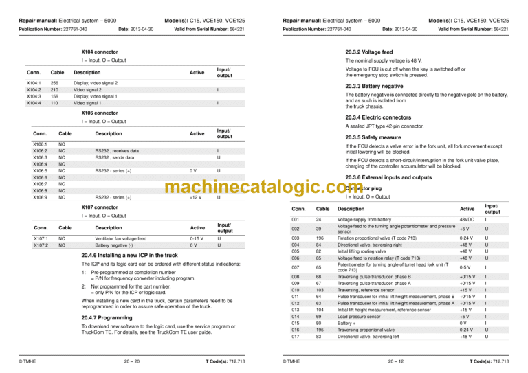
20.2.2 Voltage feed …………………………………………………………………….. 20-6
20.2.3 Battery negative ……………………………………………………………….. 20-6
20.2.4 Electric connectors ……………………………………………………………. 20-6
20.2.5 Internal status monitoring …………………………………………………… 20-6
20.2.6 Resetting the battery indicator…………………………………………….. 20-7
20.2.7 External inputs and outputs………………………………………………… 20-7
X130 connector 20-7
X131 connector 20-8
X132 connector 20-9
20.2.8 Installing a new card in the truck ……………………………………….. 20-10
20.2.9 Programming the MCU…………………………………………………….. 20-10
20.3 Fork computer unit, FCU (A4) ………………………………………………………. 20-11
20.3.1 General………………………………………………………………………….. 20-11
20.3.2 Voltage feed …………………………………………………………………… 20-12
20.3.3 Battery negative ……………………………………………………………… 20-12
20.3.4 Electric connectors ………………………………………………………….. 20-12
20.3.5 Safety measure ………………………………………………………………. 20-12
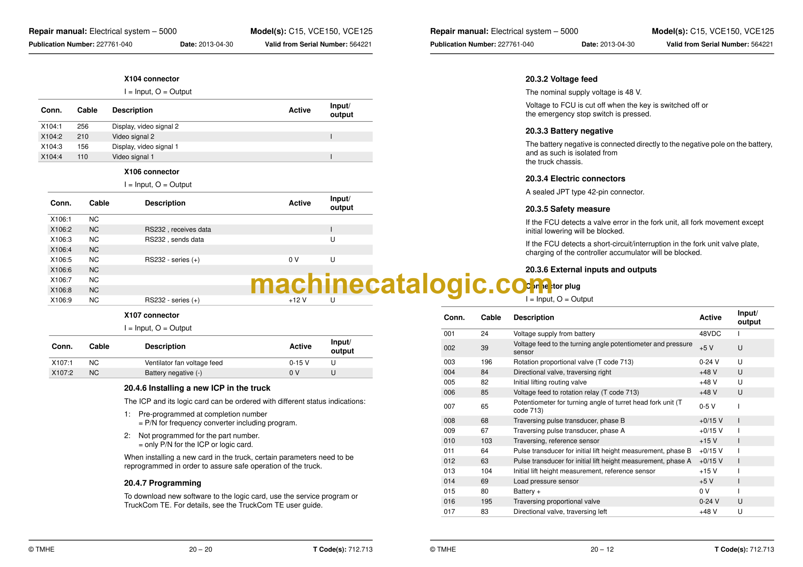
20.3.6 External inputs and outputs………………………………………………. 20-12
Connector plug 20-12
20.3.7 Installing a new card in the truck ……………………………………….. 20-13
20.3.8 Programming………………………………………………………………….. 20-13
20.4 Integrated Control Panel, ICP (A16)………………………………………………. 20-14
20.4.1 General………………………………………………………………………….. 20-14
20.4.2 ICP modules…………………………………………………………………… 20-16
20.4.3 Voltage feed …………………………………………………………………… 20-17
20.4.4 Battery negative ……………………………………………………………… 20-17
20.4.5 External inputs and outputs………………………………………………. 20-18
X100 connector 20-18
X101 connector 20-18
X102 connector 20-19
X103 connector 20-19
X104 connector 20-20
X106 connector 20-20
X107 connector 20-20
20.4.6 Installing a new ICP in the truck ………………………………………… 20-20
20.4.7 Programming………………………………………………………………….. 20-20
20.5 AC regulators, ACTL (A1), ACTR (A31) and ACH (A2)…………………….. 20-21
20.5.1 General………………………………………………………………………….. 20-21
20.5.2 Connection terminal and terminal pillars …………………………….. 20-22
20.5.3 Technical data ………………………………………………………………… 20-22
20.5.4 Installing a new frequency converter in the truck …………………. 20-23
20.5.5 Programming………………………………………………………………….. 20-23
20.5.6 Maintenance…………………………………………………………………… 20-23
20.5.7 Safety ……………………………………………………………………………. 20-23
20.5.8 Cleaning ………………………………………………………………………… 20-24
20.6 DC regulator, DCHI (A32)…………………………………………………………….. 20-24
20.6.1 General description …………………………………………………………. 20-24
20.6.2 Connection terminal and terminal pillars …………………………….. 20-25
20.6.3 Technical data ………………………………………………………………… 20-25
20.6.4 Installing a new transistor panel ………………………………………… 20-25
20.7 Parameters ………………………………………………………………………………… 20-26
20.8 Diagnostics and troubleshooting …………………………………………………… 20-26
20.8.1 Maintenance…………………………………………………………………… 20-28
20.8.2 Safety ……………………………………………………………………………. 20-28
20.8.3 Cleaning ………………………………………………………………………… 20-28
20.9 Hand-held terminal 1307 ……………………………………………………………… 20-29
20.9.1 Using the hand-held terminal ……………………………………………. 20-31
20.9.2 Viewing and adjusting parameters …………………………………….. 20-32
20.9.3 SPECIAL PROGRAM MODE……………………………………………. 20-33
20.9.4 Using the TEST mode……………………………………………………… 20-33
20.9.5 Using the DIAGNOSTICS MODE………………………………………. 20-33
20.9.6 SPECIAL DIAGNOSTICS MODE………………………………………. 20-34
20.10 Electric system, overview …………………………………………………………… 20-35
20.11 Symbol list and electric wiring diagram ………………………………………… 20-40
20.11.1 List of symbols………………………………………………………………. 20-40
20.11.2 Wiring diagram VCE150A (T code 712) ……………………………. 20-42
20.11.3 Wiring diagram VCE125ASF (T code 713) ……………………….. 20-73
20.12 Component List ………………………………………………………………………. 20-103
20.13 Component location…………………………………………………………………. 20-109
20.13.1 Cabling contacts………………………………………………………….. 20-118
20.14 Functional description, General…………………………………………………. 20-120
20.15 Functional description, starting, driving, steering and braking………… 20-121
20.15.1 Battery connected, truck switched off……………………………… 20-121
20.15.2 Log-in / Start-up…………………………………………………………… 20-121
20.15.3 Log-out / Switch-off ……………………………………………………… 20-124
20.15.4 Presence check…………………………………………………………… 20-125
20.15.5 Selecting the drive direction / Driving ……………………………… 20-126
20.15.6 Emergency driving mode………………………………………………. 20-128
20.15.7 Travel speeds……………………………………………………………… 20-129
20.15.8 Steering ……………………………………………………………………… 20-133
20.15.9 Braking ………………………………………………………………………. 20-134
20.16 Electrical description of the hydraulic functions……………………………. 20-139
20.16.1 Allowed combined functions………………………………………….. 20-139
20.16.2 Monitoring and functional limitations ………………………………. 20-140
20.16.3 Slack chain guard………………………………………………………… 20-141
20.16.4 Height measurement ……………………………………………………. 20-142
20.16.5 Cabin lifting…………………………………………………………………. 20-144
20.16.6 Special height (lift limiter function)………………………………….. 20-146
20.16.7 Cab lowering ………………………………………………………………. 20-147
20.16.8 Special function with cab lifting/lowering and
forks set straight ahead ……………………………………………………………. 20-149
20.17 Turret head unit (T code 712)……………………………………………………. 20-149
20.17.1 Auto rotation ……………………………………………………………….. 20-158
20.17.2 Miscellaneous electrical functions ………………………………….. 20-160
Warning lamp 20-160
Personal protection system (PPS) 20-160
20.17.3 Narrow aisle ID system ………………………………………………… 20-161
20.17.4 Alternative “narrow aisle systems” …………………………………. 20-162
© TMHE 1 – 7 T Code(s): 712, 713
Repair manual: Table of content Model(s): C15, VCE150A/150AC, VCE125ASF/125ASFC
Publication Number: 227761-040 Date: 2013-04-30 Valid from Serial Number: 745600FD
20.18 Shuttle fork unit (T code 713) ……………………………………………………. 20-163
20.18.1 Fork reach ………………………………………………………………….. 20-163
Function description 20-163
20.18.2 Fork lifting/lowering ……………………………………………………… 20-165
20.19 Display…………………………………………………………………………………… 20-168
20.19.1 Normal mode………………………………………………………………. 20-168
20.19.2 Information mode ………………………………………………………… 20-170
21. Parameters – 5700…………………………………………………………………………… 21-1
21.1 General……………………………………………………………………………………….. 21-1
21.2 Accessing parameters …………………………………………………………………… 21-2
21.2.1 Operator parameters (service key not inserted)…………………….. 21-2
Operator parameters (operators 1-10) 21-3
21.3 Truck parameters …………………………………………………………………………. 21-4
21.3.1 MCU parameters ………………………………………………………………. 21-6
Basic parameters 21-6
Wire guidance parameters and other new parameters 21-21
Learned calibration values, steering 21-27
Learned calibration data, wire guidance 21-30
21.3.2 FCU parameters, turret head fork unit (T code 712) …………….. 21-31
Basic parameters, turret head fork unit 21-31
Learned calibration data, turret head fork unit 21-35
21.3.3 FCU parameters, shuttle fork unit (T code 713) …………………… 21-39
21.3.4 ICP parameters ………………………………………………………………. 21-40
22. Calibration – 5700 …………………………………………………………………………… 22-1
22.1 General……………………………………………………………………………………….. 22-1
22.1.1 Accessing calibration mode………………………………………………… 22-1
22.1.2 Menu navigation ……………………………………………………………….. 22-2
22.2 Calibration of the ICP controls – “CONTROLS” …………………………………. 22-3
22.3 Calibration of steering – “STEERING”………………………………………………. 22-4
22.3.1 Calibration of the articulated centre potentiometer…………………. 22-4
22.3.2 Calibration of the control valves ………………………………………….. 22-5
22.4 Calibration of wire guidance – “WIRE” ……………………………………………… 22-6
22.4.1 “Learn Offset” …………………………………………………………………… 22-6
22.4.2 Learn frequency ……………………………………………………………….. 22-6
22.5 Calibration of the turret head fork unit functions – “FORKS”
(T code 712) ……………………………………………………………………………………….. 22-7
22.5.1 Counter-clockwise rotation …………………………………………………. 22-7
22.5.2 Clockwise rotation …………………………………………………………….. 22-7
22.5.3 Calibration of traversing/lifting, “TRAV/LIFT”…………………………. 22-8
22.5.4 Fork lowering – “LOWER” …………………………………………………… 22-9
22.6 Calibration of Shuttle fork
(T code 713) ……………………………………………………………………………………… 22-10
22.6.1 Calibration of traversing/lifting, “TRAV/LIFT”……………………….. 22-10
22.6.2 Fork lowering – “LOWER” …………………………………………………. 22-10
22.7 Calibration of weight indication – “WEIGHT”……………………………………. 22-11
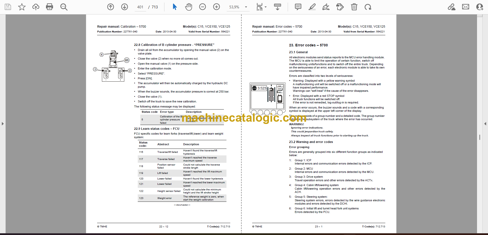
22.8 Calibration of B cylinder pressure – “PRESSURE” …………………………… 22-12
22.9 Learn status codes – FCU……………………………………………………………. 22-12
23. Error codes – 5700 ………………………………………………………………………….. 23-1
23.1 General……………………………………………………………………………………….. 23-1
23.2 Warning and error codes ……………………………………………………………….. 23-1
23.2.1 Safety logics …………………………………………………………………….. 23-2
23.3 Warning and error codes, description………………………………………………. 23-4
23.3.1 ICP, code group 1 …………………………………………………………….. 23-4
ICP warning codes 23-4
ICP error codes 23-9
23.3.2 MCU, code group 2 …………………………………………………………. 23-12
MCU warning codes 23-12
MCU error codes 23-14
23.3.3 Drive system, code group 3………………………………………………. 23-20
Drive system – warning codes 23-20
Drive system – error codes 23-22
23.3.4 Cabin lift system, code group 4 …………………………………………. 23-28
Cabin lift system – warning codes 23-28
Cabin lifting system error codes 23-33
23.3.5 Steering system, code group 5………………………………………….. 23-34
Steering system – warning codes 23-34
Steering system error codes 23-47
23.3.6 Initial lift and turret head fork unit systems, code group 6
(T code 712) …………………………………………………………………………….. 23-54
Initial lift and turret head fork unit systems – warning codes 23-54
23.3.7 Shuttle fork unit system, code group 6 (T code 713)…………….. 23-61
Initial lift and shuttle fork unit systems – warning codes 23-61
23.4 Extra logging functions ………………………………………………………………… 23-64
External log unit 23-64
24. Hydraulic system – 6000 …………………………………………………………………. 24-1
24.1 General……………………………………………………………………………………….. 24-1
24.2 Hydraulic cleanliness…………………………………………………………………….. 24-1
24.2.1 Washing ………………………………………………………………………….. 24-1
24.2.2 Packaging………………………………………………………………………… 24-1
24.2.3 Handling ………………………………………………………………………….. 24-2
24.2.4 Storage……………………………………………………………………………. 24-2
24.2.5 Work procedures ………………………………………………………………. 24-2
24.2.6 Inspection measures …………………………………………………………. 24-2
Inspection 24-2
24.3 Symbols………………………………………………………………………………………. 24-3
24.4 Cabin lifting………………………………………………………………………………….. 24-5
24.4.1 General……………………………………………………………………………. 24-5
24.4.2 Cabin lifting – S44 closed……………………………………………………. 24-5
24.4.3 Cabin lowering – S70 closed……………………………………………….. 24-5
24.4.4 AC hydraulic unit, components……………………………………………. 24-6
24.4.5 Hydraulic flow diagram, cabin lifting …………………………………….. 24-8
24.4.6 B cylinder system ……………………………………………………………… 24-9
© TMHE 1 – 9 T Code(s): 712, 713
Repair manual: Table of content Model(s): C15, VCE150A/150AC, VCE125ASF/125ASFC
Publication Number: 227761-040 Date: 2013-04-30 Valid from Serial Number: 745600FD
24.5 Fork units and steering ………………………………………………………………… 24-11
24.5.1 General………………………………………………………………………….. 24-11
24.5.2 Hydraulic flow diagram, DC system (T code 712) ……………….. 24-12
24.5.3 Hydraulic diagram (T code 713) ………………………………………… 24-13
Steering valve 24-15
Turret head fork unit valve (T code 712) 24-15
Shuttle fork valve blocks (T code 713) 24-16
24.5.4 Fork rotation (T code 712)………………………………………………… 24-16
24.5.5 Side-shift movement………………………………………………………… 24-17
24.5.6 Fork lifting………………………………………………………………………. 24-17
24.5.7 Fork lowering………………………………………………………………….. 24-18
24.5.8 Steering …………………………………………………………………………. 24-18
24.6 Extra hydraulic function (T code 712)…………………………………………….. 24-18
24.6.1 Valves used for the extra hydraulic functions………………………. 24-18
24.6.2 Hydraulic diagram, extra hydraulic function (T code 712) ……… 24-20
24.7 Operations/repair………………………………………………………………………… 24-21
24.7.1 General………………………………………………………………………….. 24-21
Work on hydraulic components 24-21
24.7.2 Filter ……………………………………………………………………………… 24-22
Overview 24-22
Filter replacement (air and oil) 24-23
24.7.3 Hydraulic hoses:……………………………………………………………… 24-25
Routing 24-25
24.7.4 Hydraulic connections ……………………………………………………… 24-27
Conical hose couplings with O–ring 24-27
Quick change connector 24-28
Assembling the quick change connector 24-28
Dismantling the quick change connector 24-29
Hydraulic couplings, for valve unit 24-30
Pipe couplings 24-31
Valves 24-32
24.7.5 General repair instructions, valves …………………………………….. 24-33
Replacing the pressure sensor 24-33
Replacing the valve assembly 24-34
Replacing a valve section 24-35
Composition of valve unit 24-36
Replacing valve insert, routing valves 24-38
Installing the valve in the truck 24-40
Tightening torque 24-42
Replacing the non-return valve in the control valve 24-43
25. Hydraulic tank – 6110 ………………………………………………………………………. 25-1
25.1 Replace the hydraulic oil ……………………………………………………………….. 25-1
25.1.1 Emptying the tank……………………………………………………………… 25-1
25.1.2 Filling the tank ………………………………………………………………….. 25-2
25.2 Replacing the tank………………………………………………………………………… 25-2
25.3 Installing a new tank ……………………………………………………………………… 25-6
26. Hydraulic pump – 6140 ……………………………………………………………………. 26-1
26.1 General……………………………………………………………………………………….. 26-1
26.2 Bleeding the hydraulic pump ………………………………………………………….. 26-3
26.2.1 Bleeding the hydraulic pump for steering and fork hydraulics (B)26-3
26.2.2 Bleeding the hydraulic pump for main lift (A1, A2) …………………. 26-4
26.3 Replacing the hydraulic pump for main lift (A1, A2) …………………………… 26-4
26.3.1 Disassembly …………………………………………………………………….. 26-4
26.3.2 Installation ……………………………………………………………………….. 26-6
26.4 Replacing the hydraulic pump for steering and fork hydraulics (B) ………. 26-8
26.4.1 Disassembly …………………………………………………………………….. 26-8
26.4.2 Installation ……………………………………………………………………… 26-10
26.5 Troubleshooting internal leakage in the hydraulic pump for
steering and fork hydraulics (B)……………………………………………………………. 26-12
27. Accumulators – 6280 ………………………………………………………………………. 27-1
27.1 Charging of the lifting and steering accumulators ……………………………… 27-1
27.1.1 Preparations …………………………………………………………………….. 27-2
27.1.2 Measuring the pressure in the lifting accumulator………………….. 27-3
27.1.3 Charging the lifting accumulator………………………………………….. 27-6
27.1.4 Order numbers for country-specific adapter kits. …………………… 27-7
27.2 Measuring the pressure in the steering accumulator………………………….. 27-8
27.2.1 Charging the steering accumulator ……………………………………. 27-10
28. Main lift cylinder – 6610…………………………………………………………………… 28-1
28.1 Replacing the seal in the B cylinder ………………………………………………… 28-1
29. Main mast and mast – 7100……………………………………………………………… 29-1
29.1 Setting the cab and mast stoppers ………………………………………………….. 29-1
29.1.1 Cab stoppers ……………………………………………………………………. 29-1
29.1.2 Setting the cab stoppers…………………………………………………….. 29-2
29.1.3 Mast stoppers…………………………………………………………………… 29-5
30. Main lift chain system – 7120…………………………………………………………… 30-1
30.1 General……………………………………………………………………………………….. 30-1
30.2 Checking the chain setting …………………………………………………………….. 30-1
30.3 Checking the chain ……………………………………………………………………….. 30-1
30.3.1 Noise ………………………………………………………………………………. 30-1
30.3.2 Surface rust ……………………………………………………………………… 30-1
30.3.3 Rusty links ……………………………………………………………………….. 30-1
30.3.4 Stiff links ………………………………………………………………………….. 30-2
30.3.5 Bolt rotation ……………………………………………………………………… 30-2
30.3.6 Loose bolts ………………………………………………………………………. 30-2
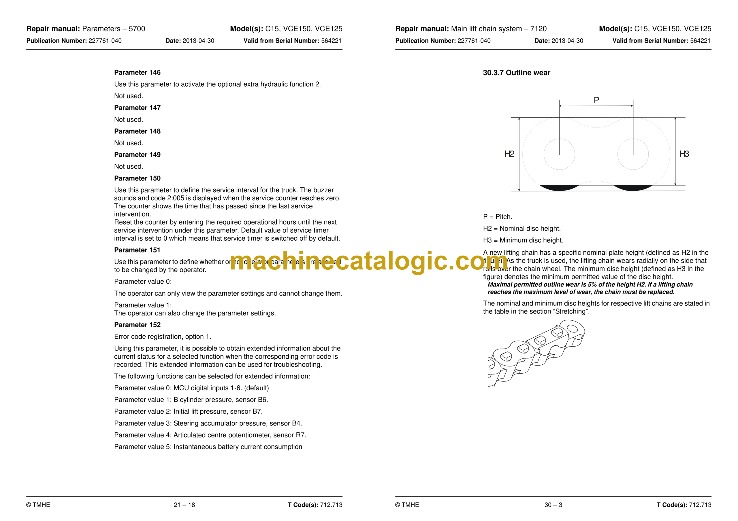
30.3.7 Outline wear …………………………………………………………………….. 30-3
30.3.8 Stretching ………………………………………………………………………… 30-4
30.3.9 Damage…………………………………………………………………………… 30-4
30.3.10 Damaged discs……………………………………………………………….. 30-5
30.3.11 Damaged bolts ……………………………………………………………….. 30-5
30.3.12 Dirty chain ……………………………………………………………………… 30-5
30.4 Cleaning ……………………………………………………………………………………… 30-5
30.5 Lubrication …………………………………………………………………………………… 30-6
30.6 Adjusting chains …………………………………………………………………………… 30-7
30.6.1 Tool list ……………………………………………………………………………. 30-7
30.6.2 Main lift chain adjustment…………………………………………………… 30-7
30.6.3 Cabin chain adjustment……………………………………………………… 30-9
30.6.4 Initial mast chain adjustment ………………………………………………. 30-9
31. Initial mast/Turret head fork unit – 7200 (T code 712) ……………………….. 31-1
31.1 General description ………………………………………………………………………. 31-1
31.2 Assembly/disassembly of the initial mast …………………………………………. 31-2
31.2.1 Mast assembly …………………………………………………………………. 31-2
31.2.2 Installation of belts on a new truck ………………………………………. 31-6
31.2.3 Installing the hydraulic hose and electric cabling …………………… 31-8
31.2.4 Mast disassembly……………………………………………………………… 31-9
© TMHE 1 – 11 T Code(s): 712, 713
Repair manual: Table of content Model(s): C15, VCE150A/150AC, VCE125ASF/125ASFC
Publication Number: 227761-040 Date: 2013-04-30 Valid from Serial Number: 745600FD
31.3 Inspection and replacement of belts used for fork traversing …………….. 31-10
31.3.1 Check ……………………………………………………………………………. 31-10
31.3.2 Replacing the belt……………………………………………………………. 31-10
31.3.3 Checking belt tensioning ………………………………………………….. 31-13
31.4 Friction plate adjustment ……………………………………………………………… 31-15
31.5 Parallel adjustment of forks ………………………………………………………….. 31-16
31.5.1 Measuring fork parallelism ……………………………………………….. 31-17
32. Shuttle fork – 7800 (T code 713) ……………………………………………………… 32-1
32.1 Assembly of the shuttle fork …………………………………………………………… 32-1
32.2 Maintenance ………………………………………………………………………………… 32-4
32.2.1 Maintenance schedule ………………………………………………………. 32-4
32.2.2 Lubrication……………………………………………………………………….. 32-6
Oil and lubricant specification 32-6
32.2.3 Chain adjustment ……………………………………………………………… 32-6
32.3 Replacing the shuttle forks …………………………………………………………….. 32-9
32.4 Measures…………………………………………………………………………………… 32-12
32.4.1 Shuttle forks coming loose from the fork carriage holders …….. 32-12
33. Magnet installation in narrow aisle – 8100 ………………………………………… 33-1
33.1 General……………………………………………………………………………………….. 33-1
33.2 Magnetic Sensor Switch Positions ………………………………………………….. 33-3
33.3 Standard Magnet Positions – Rail and Wire Guided ………………………….. 33-4
33.3.1 Number of magnet positions required per aisle……………………… 33-5
33.4 Aisle indication – method of operation ……………………………………………… 33-5
33.5 Aisle End Brake ……………………………………………………………………………. 33-6
33.5.1 How the AEB works…………………………………………………………… 33-6
33.5.2 AEB Magnet Positions……………………………………………………….. 33-7
34. Wire guidance equipment – 8200 …………………………………………………….. 34-1
34.1 General……………………………………………………………………………………….. 34-1
34.2 Generator ……………………………………………………………………………………. 34-2
34.2.1 Technical data ………………………………………………………………….. 34-2
35. Height preselection – 9390………………………………………………………………. 35-1
35.1 General……………………………………………………………………………………….. 35-1
35.2 Parameters ………………………………………………………………………………….. 35-1
35.2.1 MCU parameters ………………………………………………………………. 35-1
35.3 Programming ……………………………………………………………………………….. 35-2
35.3.1 Programming a level …………………………………………………………. 35-3
35.3.2 Operation/Automatic operations………………………………………….. 35-4
36. Appendix A: Technical update…………………………………………………………. 36-1
36.1 AC pump motor, C code 1710, main lift……………………………………………. 36-2
36.1.1 Description ………………………………………………………………………. 36-2
36.1.2 Replacing the temperature sensor ………………………………………. 36-4
36.1.3 Replacing the speed sensor……………………………………………….. 36-5
36.1.4 Replacing bearings……………………………………………………………. 36-7
36.2 AC drive motor, C code 1760 ……………………………………………………….. 36-12
36.2.1 Description …………………………………………………………………….. 36-12
36.2.2 Replacing the temperature sensor …………………………………….. 36-13
36.2.3 Replacing the speed sensor……………………………………………… 36-13
36.2.4 Disassembly …………………………………………………………………… 36-14
36.2.5 Replacing bearings………………………………………………………….. 36-17
36.2.6 Assembly……………………………………………………………………….. 36-1
36.3 Motor controllers, C code 5460, ACTL (A1), ACTR (A31) and
ACH (A2) generation 5 ……………………………………………………………………….. 36-21
36.3.1 General………………………………………………………………………….. 36-21
36.3.2 ACT regulators, A1/A31 …………………………………………………… 36-22
Technical data, ACT regulators 36-23
36.3.3 ACH regulator, A2 …………………………………………………………… 36-24
Technical data, ACH regulator 36-25
36.3.4 Troubleshooting………………………………………………………………. 36-26
Troubleshooting chart, motor controller 36-27
36.3.5 Connection of power cables ……………………………………………… 36-37
36.3.6 Installing a new frequency converter in the truck …………………. 36-37
36.3.7 Programming………………………………………………………………….. 36-37
36.3.8 Maintenance…………………………………………………………………… 36-38
36.3.9 Safety ……………………………………………………………………………. 36-38
36.3.10 Cleaning ………………………………………………………………………. 36-38
36.4 New pivot point/steering potentiometer for C15, VCE150A and
VCE125ASF ……………………………………………………………………………………… 36-39
36.4.1 General information…………………………………………………………. 36-39
36.4.2 Replacing the potentiometer …………………………………………….. 36-40
The potentiometer’s voltage can be read via TruckCom 36-40
The potentiometer’s voltage cannot be read via TruckCom 36-40
36.5 Wiring diagram VCE150 (T code 712)
from serial number 6213314………………………………………………………………… 36-41
36.6 Wiring diagram VCE125ASF (T code 713)
from serial number 6213314………………………………………………………………… 36-71
37. Index………………………………………………………………………………………………. 37


