Format: PDF (Printable Document)
File Language: English
Brand: BT
Model: HT60W Hand Pallet
Type of Document: Maintenance, Operator and Parts Manual
$ 70
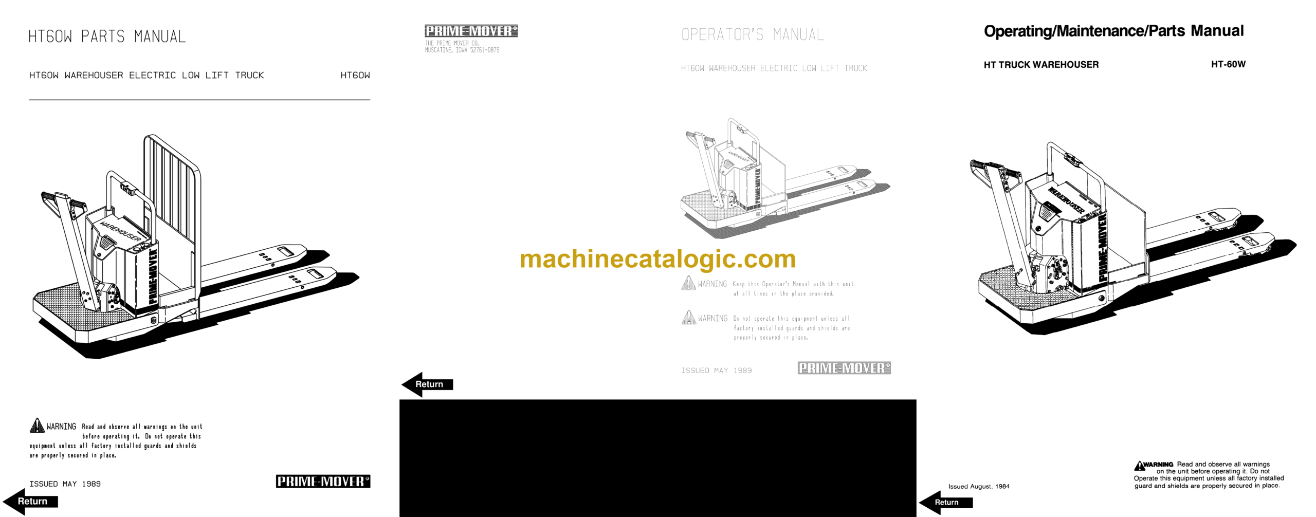
BT HT60W Hand Pallet Maintenance, Operator and Parts Manual
Front Cover
Parts Ordering Instructions
Field Modifications
General Information
Alphabetical Index
Figure # 0.1 Decals and Parts Assembly
Figure # 0.2 Parts List and Service Reference Index
Figure # 1.1 Transmission and Handle Assembly
Figure # 1.2 Handle Assembly
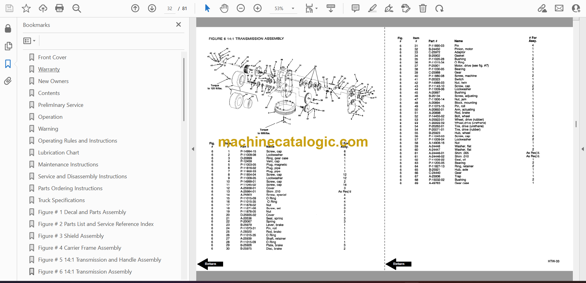
Figure # 1.3 Part 1 14:1 Transmission Assembly
Figure # 1.4 Part 2 14:1 Transmission Assembly
Figure # 2.1 Resistor Master Control Switch
Figure # 2.2 EV-100/EV-1 SCR Master Control Switch
Figure # 2.3 Resistor Electrical Schematic
Figure # 2.4 Resistor Electrical Schematic Symbols
Figure # 2.5 Resistor Control Wiring Harness Assembly
Figure # 2.6 Third Speed Control Wiring
Figure # 2.7 Third Speed Power Component Wiring
Figure # 2.8 Resistor Control Panel Assembly
Figure # 2.9 Contactor Assembly
Figure # 2.10 Forward & Rearward Contactor Assembly
Figure # 2.11 Third Speed Contactor Panel Assembly
Figure # 2.12 Fourth Speed Control Wiring
Figure # 2.13 Fourth Speed Power Component Wiring
Figure # 2.14 Fourth Speed Contactor Panel Assembly
Figure # 2.15 Contactor Assembly
Figure # 2.16 EV-100 SCR Trucks Electrical Schematic
Figure # 2.17 EV-100 SCR Truck Electrical Schematic Symbols
Figure # 2.18 EV-100 SCR Control Wiring
Figure # 2.19 EV-100 SCR Third Speed Power Component Wiring
Figure # 2.20 EV-100 SCR Contactor Panel Assembly
Figure # 2.21 EV-100 SCR Forward & Rearward Contactor Assembly
Figure # 2.22 EV-100 1A Contactor Assembly
Figure # 2.23 EV-100 SCR Third Speed Pump Contactor Panel Assembly
Figure # 2.24 EV-100 SCR Fourth Speed Power Component Wiring
Figure # 2.25 EV-100 SCR Fourth Speed Contactor Panel Assembly
Figure # 2.26 EV-100 SCR Third & Fourth Speed Control Panel
Figure # 2.27 Power Connector Assembly
Figure # 2.28 Hydraulic Pump Motor Assembly
Figure # 2.29 Drive Motor Assembly
Figure # 2.30 Wiring Assembly for Cold Storage
Figure # 3.1 Hydraulic Schematic
Figure # 3.2 Hydraulic Schematic Symbols
Figure # 3.3 Hydraulic System
Figure # 3.4 Pump and Motor Assembly
Figure # 3.5 Lift Cylinder Assembly
Figure # 4.1 Shielding Assembly
Figure # 4.2 Carrier Frame Assembly
Figure # 4.3 Caster Assembly
Figure # 4.4 Lift Frame Assembly
Figure # 4.5 Pallet Entry Rollers
Figure # 4.6 Skid Adapter and Package Guard Assembly
Figure # 4.7 Removable Load Backrest
Figure # 6.1 Special Tools and Lubrications
Numerical Index
Back Cover
Front Cover
Warranty
New Owners
Contents
PrelimInary Service
Operation
Warning
Operating Rules and Instructions
Lubrication Chart
Maintenance Instructions
Service and Disassembly Instructions
Parts Ordering Instructions
Truck Specifications
Figure # 1 Decal and Parts Assembly
Figure # 2 Parts List and Service Reference Index
Figure # 3 Shield Assembly
Figure # 4 Carrier Frame Assembly
Figure # 5 14:1 Transmission and Handle Assembly
Figure # 6 14:1 Transmission Assembly
Figure # 7 14:1 Motor Assembly
Figure # 8 Handle Assembly
Figure # 9 Master Control Switch Assembly
Figure # 10 Master Control Switch Assembly
Figure # 11 Spring Loaded Caster Assembly
Figure # 12 Electrical Schematic Symbols
Figure # 13 Resistor Truck Electrical Schematic
Figure # 14 Control Wiring Harness Assembly
Figure # 15 Third Speed Riding Control Wiring
Figure # 16 Third Speed Power Component Wiring
Figure # 17 Control Panel Assembly
Figure # 18 GE Contactor Assembly
Figure # 19 GE Contactor Assembly
Figure # 20 Third Speed Panel Assembly
Figure # 21 Fourth Speed Control Wiring
Figure # 22 Fourth Speed Power Component Wiring
Figure # 23 Fourth Speed Contactor Panel Assembly
Figure # 24 Contactor Assembly
Figure # 25 EV-1 SCR Electrical Schematic
Figure # 26 Control Wiring Harness Assembly
Figure # 27 EV-1 Bracket Assembly
Figure # 28 EV-1 Power Component Wiring
Figure # 29 EV-1 Contactor Panel Assembly
Figure # 30 GE Contactor Assembly
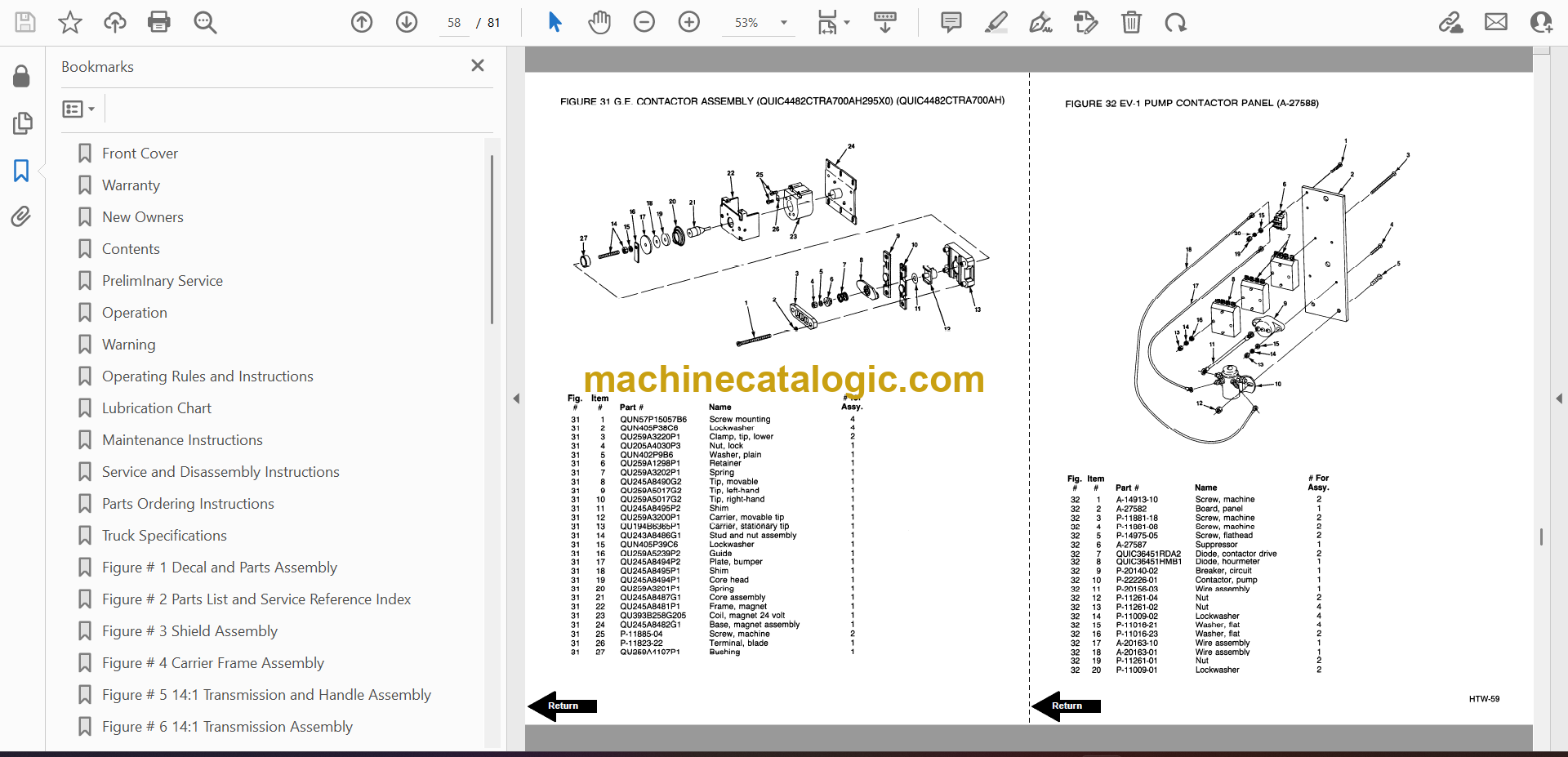
Figure # 31 GE Contactor Assembly
Figure # 32 EV-1 Pump Contactor Panel
Figure # 33 EV-1 SCR Control
Figure # 34 Transformer Assembly
Figure # 35 Rectifier Heat Sink Assembly
Figure # 36 Power Connector Assembly
Figure # 37 Cold Storage of Master Control Switch
Figure # 38 Dynamic Brake Assembly
Figure # 39 Hydraulic Schematic
Figure # 40 Hydraulic Schematic Symbols
Figure # 41 Hydraulic System
Figure # 42 Hydraulic Pump and Motor Assembly
Figure # 43 Motor Assembly
Figure # 44 Cylinder Assembly
Figure # 45 Lift Frame Assembly
Figure # 46 Pallet Entry Rollers
Figure # 47 Skid Adapter and Package Guard Assembly
Figure # 48 Removable Load Backrest
Service Guide
Back Cover


