Format: PDF (Printable Document)
File Language: English
Brand: BT
Model: HX80 Forklift
Type of Document: Operator and Parts Manual
$ 70
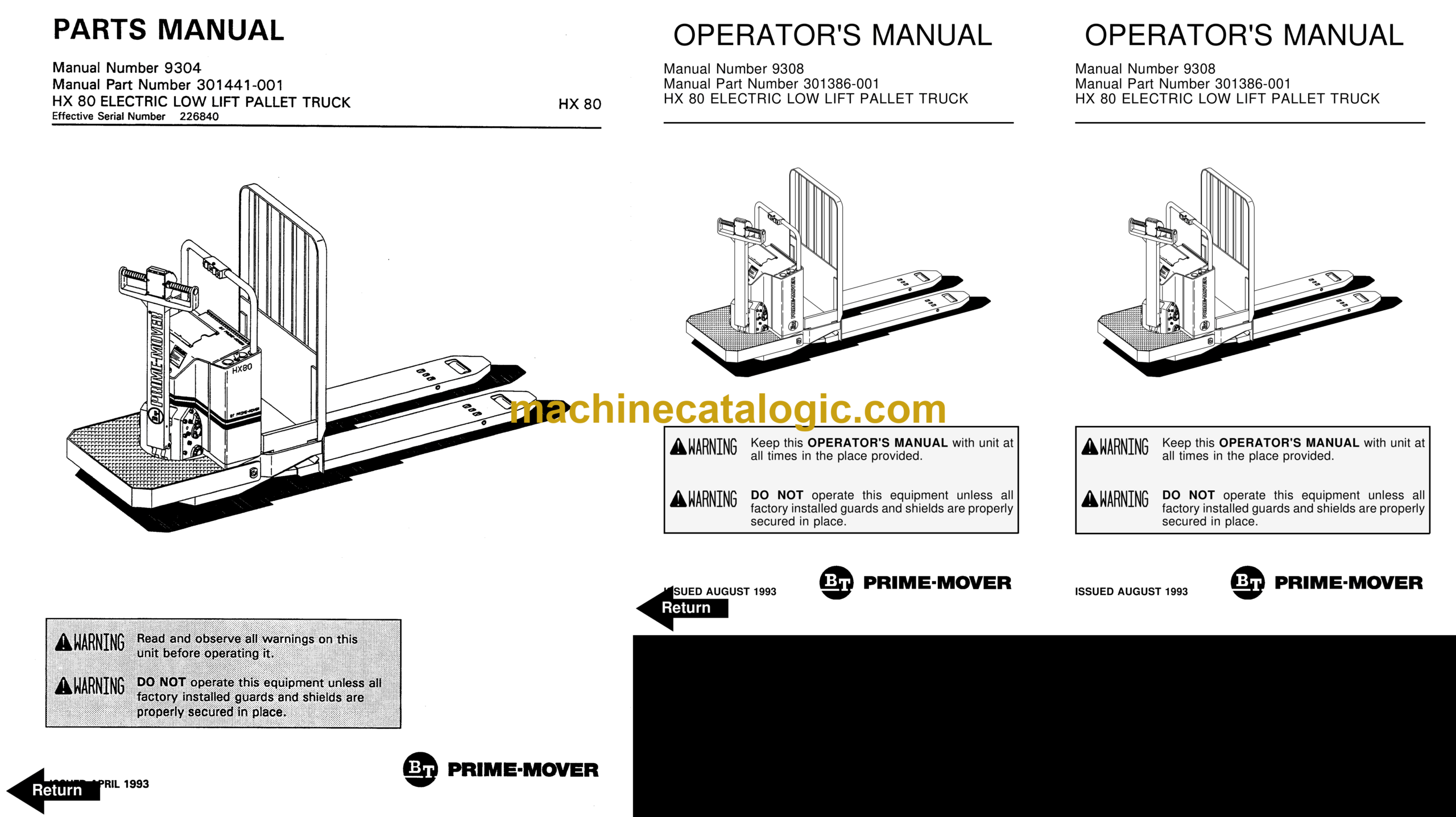
BT HX80 Forklift Operator and Parts Manual
Front Cover
Parts Ordering Instructions
Field Modifications
General Information
Alphabetical Index
Figure # 0.1 Decals and Parts Assembly
Figure # 0.2 Parts List Index
Figure # 1.1 Transmission and Handle Assembly
Figure # 1.2 Twist Grip Resistor & Transistor Control Handle Assembly
Figure # 1.3 Thumb Control Resistor & Transistor Control Handle Assembly
Figure # 1.4 Part 1 Transmission Assembly
Figure # 1.5 Part 2 Transmission Assembly
Figure # 2.1 Resistor Electrical Schematic
Figure # 2.2 Resistor Electrical Schematic Symbols
Figure # 2.3 Resistor Control Wiring Harness Assembly
Figure # 2.4 Resistor Third Speed Control Wiring
Figure # 2.5 Resistor Third Speed Power Component Wiring
Figure # 2.6 Resistor Control Panel Assembly, 24 Volt
Figure # 2.7 Contactor Assembly, 24 Volt
Figure # 2.8 Forward & Rearward Contactor Assembly, 24 Volt
Figure # 2.9 Third Speed Contactor Panel Assembly
Figure # 2.10 Fourth Speed Control Wiring
Figure # 2.11 Fourth Speed Power Component Wiring
Figure # 2.12 Fourth Speed Contactor Panel Assembly
Figure # 2.13 Contactor Assembly
Figure # 2.14 Resistor Power Connector Assembly
Figure # 2.15 Transistor Electrical Schematic
Figure # 2.16 Transistor Electrical Schematic Symbols
Figure # 2.17 Transistor Control Wiring Harness Assembly
Figure # 2.18 Transistor Power Component Wiring
Figure # 2.19 Control Panel Assembly, 24 Volt
Figure # 2.20 Forward & Rearward Contactor Assembly, 24 Volt
Figure # 2.21 1A Contactor Assembly, 24 Volt
Figure # 2.22 High Speed Contactor Assembly, 24 Volt
Figure # 2.23 Transistor Power Connector Assembly
Figure # 2.24 Pump Motor Assembly, 24 Volt
Figure # 2.25 Drive Motor Assembly
Figure # 3.1 Hydraulic Schematic
Figure # 3.2 Hydraulic Schematic Symbols
Figure # 3.3 Resistor Hydraulic System
Figure # 3.4 Transistor Hydraulic System
Figure # 3.5 Pump and Motor Assembly
Figure # 3.6 Lift Cylinder Assembly
Figure # 4.1 Shielding Assembly
Figure # 4.2 Carrier Frame Assembly
Figure # 4.3 Caster Assembly
Figure # 4.4 Lift Frame Assembly
Figure # 4.5 Pallet Entry Rollers
Figure # 4.6 Skid Adapter and Package Guard Assembly
Figure # 4.7 Removable Load Backrest
Figure # 10.1 Special Tools and Lubrications
Numerical Index
Back Cover
Front Cover
Important Notice
Foreword
Table of Contents
Drive Safely
Introduction
Preliminary Service
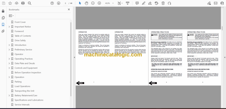
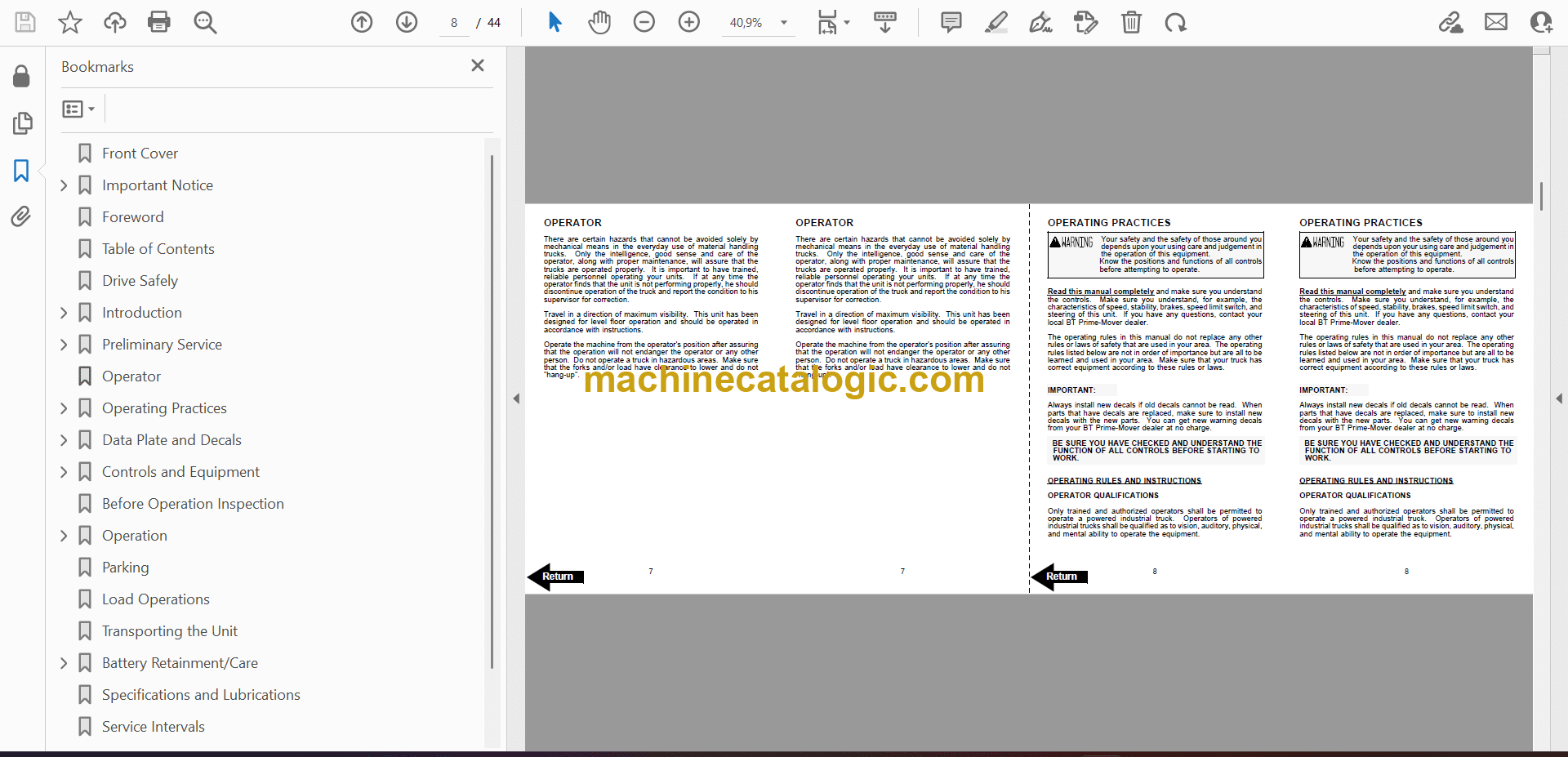
Operator
Operating Practices
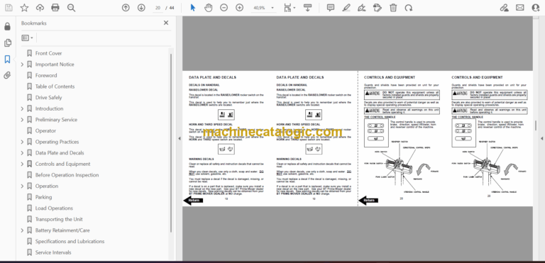
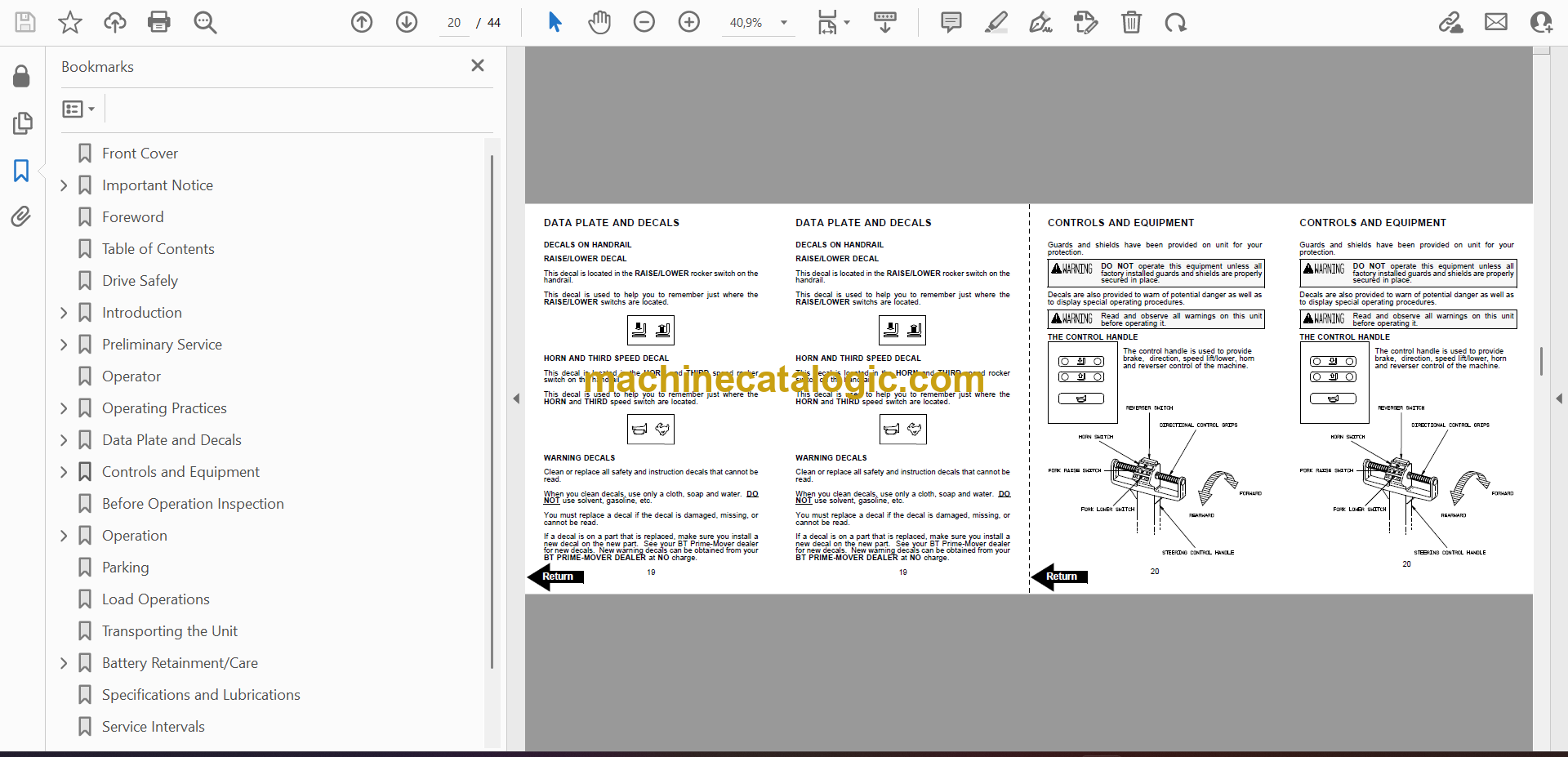
Data Plate and Decals
Controls and Equipment
Before Operation Inspection
Operation
Parking
Load Operations
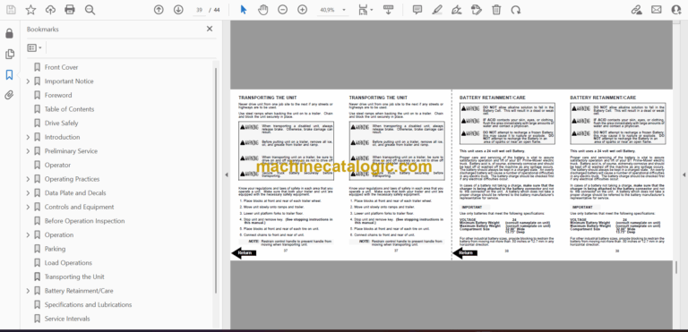
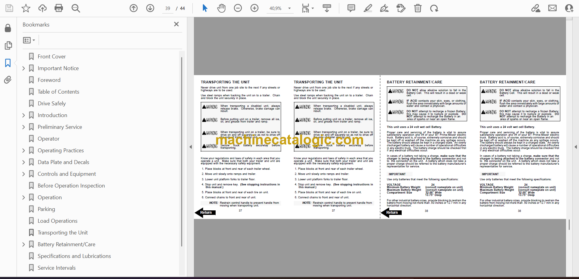
Transporting the Unit
Battery Retainment/Care
Specifications and Lubrications
Service Intervals
Field Modifications
Back Cover
