Format: PDF (Printable Document)
File Language: English
File Pages: 1070
File Size: 55.36 MB (Speed Download Link)
Brand: BT
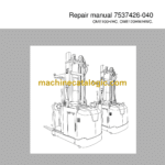
Model: OME100H, OME100HC, OME120HW, OME120HWC
Part No: 7537426-040
Type of Document: Repair Manual
$ 40
1. Table of contents
2. General introduction
2.1 How to use this manual
2.2 Warning symbols
2.3 Pictograms
3. General safety rules
3.1 Work safety
3.2 Electrical system
3.3 Safe lifting
3.4 Truck modifications
4. Chassis C0000
4.1 Overview
4.2 Description
4.3 Inspection covers C0340
4.4 Battery compartment C0390
4.5 Cab C0560
4.6 Cab walls C0520
4.7 Side gates C0550
4.8 Seat mountings C0610
4.9 Operator’s seat C0620
4.10 Operator controls (mechanical) C0640
4.11 Wall/floor covering C0670
4.12 Interior fittings C0680
4.13 Design plate
4.14 Mirrors C0740
4.15 Safety equipment C0800
4.16 Overhead guard/roof C0810
4.17 Finger guards C0820
4.18 Signs, warnings, labels C0850
5. Motors C1000
5.1 Overview
5.2 Description
5.3 Pump motor C1710
5.4 Steering servo motor C1730
5.5 Fan motors C1740
5.6 Drive motor, C1760
6. Transmission/drive gear C2000
6.1 Overview
6.2 Drive gear C2550
7. Brake system/Wheels C3000
7.1 Overview
7.2 Brake system C3100
7.3 Parking brake C3300
7.4 Parking brake C3370
7.5 Emergency brake release
7.6 Wheels C3500
7.7 Wheel track C3510
7.8 Drive wheel C3530
7.9 Support arm wheel C3550
7.10
7.11 Side guide wheel C3580 (option)
8. Steering system C4000
8.1 Electric steering system C4300
8.2 Electric steering wheel C4310
8.3 Steering unit C4330
8.4 Steering harness C4340
8.5 Steering angle reference sensor C4350
8.6 Steering bearing C4380
8.7 Wire guidance C4510
8.8 Wire guidance, antennas C4540
8.9 Wiring harness for wire/rail guidance C4550
8.10 Rail guidance C4510
8.11 Wire guidance, antenna C4540
8.12 Wire guidance, wiring harness C4550
9. Electrical system C5000
9.1 Cabling C5100
9.2 Battery C5110
9.3 Lighting C5120
9.4 Sound and light signals C5160
9.5 Main contactor C5190.
9.6 Central Information Display – CID C5200
9.7 Height indicator/preselector (Option)
9.8 Speed control C5330
9.9 Output control
9.10 Pump motor – ACH C5660
9.11 Function control C5510
9.12 Main processor – MCU C5710
9.13 Fuse panels C5790
9.14 Sending units and sensors C5800
9.15 Position sensor, lift/lowering C5820
9.16 Safety sensor C5830
9.17 Narrow aisle sensor C5840
9.18 Positioning sensor C5850
10. § Hydraulic system C6000
10.1 Hydraulic cleanliness
10.2 Hydraulic unit C6100
10.3 Filter C6130
10.4 Main valve C6210
10.5 Hydraulic hoses C6230
10.6 Hydraulic cylinders C6600
11. Mast C7000
11.1 Available combinations
11.2 Cab lift C7100
11.3 Cab lift chain system C7120
11.4 Damper C7150
11.5 Initial lift C7160
11.6 Main mast mountings C7190
11.7 Forks C7410
12. Peripherals C8000
12.1 Magnet layout
12.2 Photocell layout
13. Options/Extra equipment C9000
13.1 Radio equipment C9330
13.2 Extra lighting C9360
13.3 Other extra equipment C9500
14. Operation and connection sequences
14.1 Battery is connected
14.2 Logging in
14.3 Basic control criteria
14.4 Driving outside narrow aisle
14.5 Driving in narrow aisle
14.6 Braking in neutral
14.7 Reverse braking
14.8 Brake operation via controls
14.9 Steering
14.10 Initial lift up
14.11 Initial lift down
14.12 Cab lift up
14.13 Cab lift down
14.14 Logout
14.15 Emergency lowering
15. Parameters
15.1 Definition of cab height
15.2 Display/change parameters
15.3 Operator parameters
15.4 General service parameters
15.5 Service parameters, travel functions
15.6 Service parameters, hydraulics
15.7 Service parameters, CID
15.8 Service parameters, VNA
15.9 General factory parameters
15.10 Factory parameters, narrow aisle
15.11 Factory parameters, activation of options
15.12 Parameter 1119 – Lockable side gates, cab
15.13 Parameter 1120 – Lockable side gates, platform
15.14 Parameter 1121 – Lockable front gates, platform
15.15 Parameter 1122 – Lockable front gates, cab
15.16 Factory parameters, calibration
16. Installation
16.1 Transporting the truck
16.2 Taking into operation
17. Maintenance
17.1 Introduction
17.2 Safety precautions for maintenance work
17.3 Maintenance instructions
17.4 Symbols
17.5 Safety check
17.6 First service – 250 h
17.7 Periodic maintenance
18. Troubleshooting
18.1 Auxiliary functions
18.2 Initial troubleshooting
18.3 Troubleshooting using blocking symbol
18.4 Troubleshooting using error codes
18.5 Troubleshooting without an error code
19. Chassis C0000
19.1 Frame/Chassis C0300
19.2 Floor C0330
19.3 Hoods and covers C0340
19.4 Battery compartment parts C0390
19.5 Frame/chassis components C0400
19.6 Cab anchorage C0510
19.7 Cab walls C0520
19.8 Side gates C0550
19.9 Cab C0560
19.10 Seat mountings C0610
19.11 Operator’s seat C0620
19.12 Operator controls C0640
19.13 Wall/floor covering C0670
19.14 Interior fittings C0680
19.15 Mirrors C0740
19.16 Safety equipment C0800
19.17 Overhead guard C0810
19.18 Finger guards C0820
19.19 Signs, warnings and adhesive labels C0850
20. Motors C1000
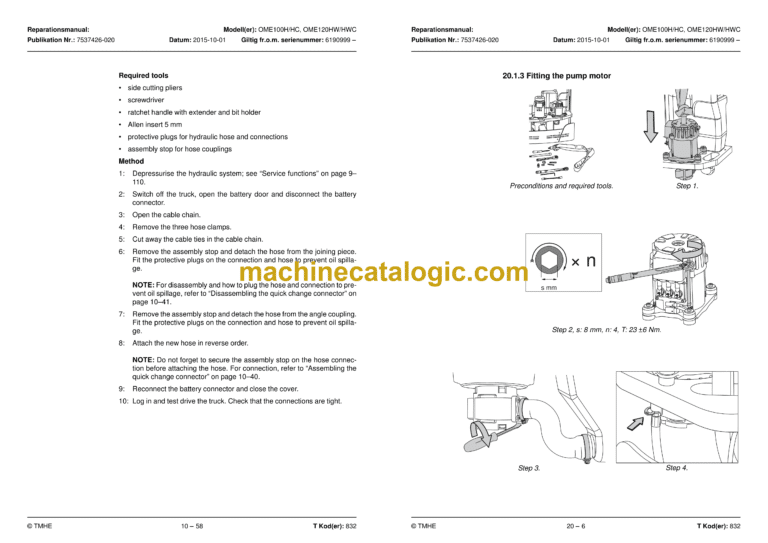
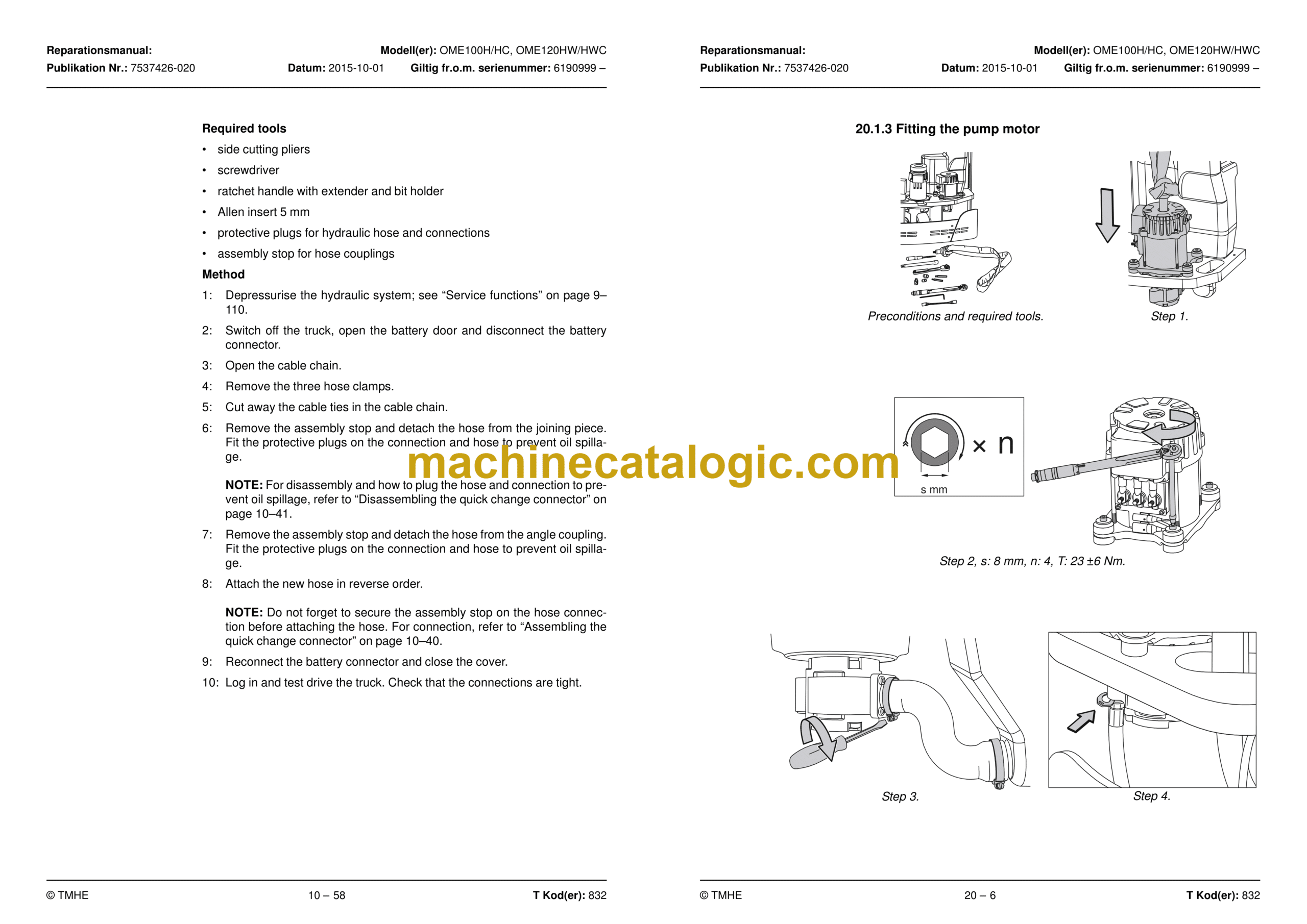
20.1 Pump motor C1710
20.2 Steering servo motor C1730
20.3 Fan motor C1740
20.4 Drive motor, C1760
21. Drive gear C2000
21.1 Drive gear C2550
22. Brake/wheel systems C3000
22.1 Support arm brake C3180
22.2 Parking brake C3370
22.3 Emergency brake release
22.4 Drive wheel C3530
22.5 Support arm wheel C3550
22.6 Side guide wheel C3580 (option)
23. Steering system C4000
23.1 Electric steering system C4300
23.2 [B17] Steering angle reference sensor C4350
23.3 Steering bearing C4380
23.4 Wire guidance C4510
23.5 Wire guidance, antennas C4540
23.6 Wiring harness for wire/rail guidance C4550
24. Electrical system C5000
24.1 Cabling C5100
24.2 Battery C5110
24.3 Lighting C5120
24.4 Sound and light signals (alarms) C5160
24.5 [Q10] Main contactor C5190
24.6 Information displays CID/LID – C5200
24.7 Speed control C5330
24.8 Senders and sensors C5380
24.9 Output control – Drive motor (ACT) C5460
24.10 Function control C5510
24.11 Output control, pump motor (ACH) C5660
24.12 Main processor MCU C5710
24.13 Fuse panel C5790
24.14 Position sensor C5820
24.15 Safety sensor C5830
24.16 Aisle identification sensor C5840
24.17 Positioning sensor C5850
24.18 Parameter settings
24.19 Calibrations
25. Hydraulic system C6000
25.1 Hydraulic cleanliness
25.2 Hydraulic unit C6100
25.3 Main valve C6210
25.4 Hydraulic hoses C6230
25.5 Hydraulic cylinders C6600
26. Mast/Lift system C7000
26.1 Cab lift C7100
26.2 Cab lift C7110
26.3 Cab lift chain system C7120
26.4 Damping C7150
26.5 Initial lift C7160
26.6 Main mast mountings C7190
26.7 Forks C7410
27. Peripherals C8000
28. Options/Extra equipment C9000
28.1 Extra electrical equipment C9300
28.2 Extra electrical equipment C9400
28.3 Other extra equipment C9500
Appendix A – Instructions for disposal
0.1 General
0.2 Marking of plastics
0.3 Pressure vessels
0.4 Sorting categories
Appendix B – Wiring diagram
0.5 Components
0.6 Overview
0.7 Detailed diagrams
Appendix C – Hydraulics schematics
0.8 Components
0.9 Truck with initial lift
0.10 W model
Appendix D – Tools
0.11 AMP contacts
0.12 MQS contacts
0.13 CPC contacts
0.14 Other tools
Appendix E – Service data and grease specifications
0.15 General tightening torques
0.16 Oil and grease specification
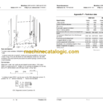
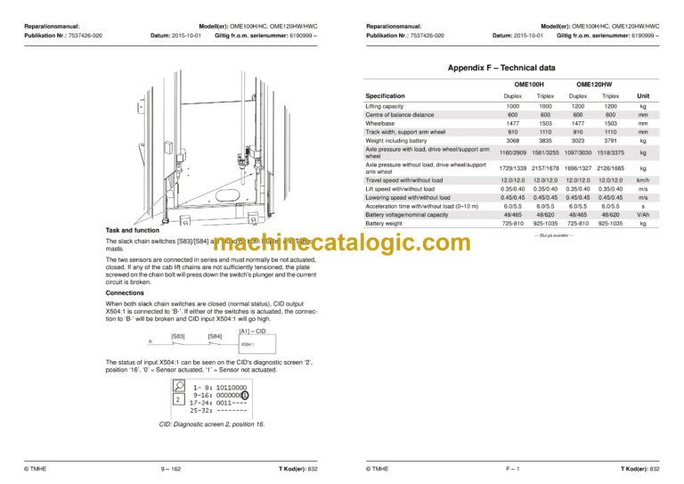
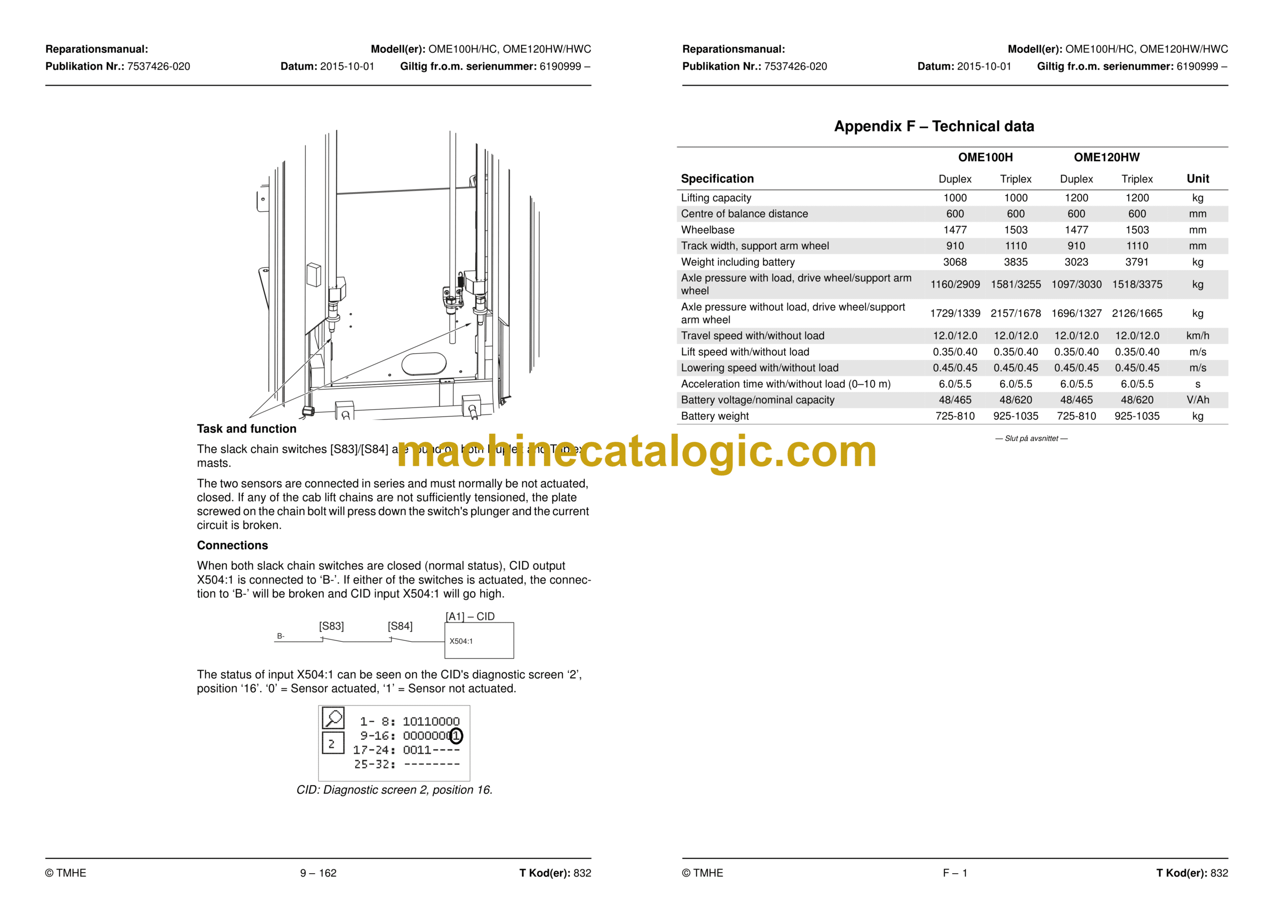
Appendix F – Technical data
Bilaga G – Index
