Format: PDF (Printable Document)
File Language: English
File Pages: 226
File Size: 9.19 MB (Speed Download Link)
Brand: BT
Model: Opus OL25, OL25P Electric Pallet Truck
Type of Document: Master Service Manual
$ 40
1- Table of contents
2- Technical data – M4
2.1 Tightening torques
2.2 General tightening torques
2.3 Truck dimensions
3- Destruction instructions – M6
3.1 General
3.2 Procedure
3.3 Abbreviations
3.4 Sorting
3.5 Hoods, hatches (0340)
3.6 Hoods, hatches (0340)
3.7 Frame/chassis (0300) and forkframe (0380)
3.8 Seat, cushions (0620)
3.9 Wall/floor covering (0670)
3.10 Internal fittings (0680)
3.11 Driver protection (0840)
3.12 Electric motors (1700)
3.13 Drive assembly/gear (2550)
3.14 Wheels (3500)
3.15 Steering arm (4110)
3.16 General electronic equipment (5100)
3.17 Battery cut out connector/ contactor (5190)
3.18 Extra I/O module (5730)
3.19 Hydraulic unit (6100)
3.20 Hydraulic lines chassis (6230) and main lift cylinders (6610)
3.21 Charger adaptor (9380)
3.22 Terminal on board (9410)
3.23 Other extra equipment, tuck log device (9420)
3.24 Other extra equipment, load support (9500)
3.25 Other extra equipment, writing table (9500)
3.26 Other extra equipment, writing table (9500)
3.27 Other extra equipment, support (9500)
3.28 Other extra equipment, collision protection (9500)
3.29 Other extra equipment, working cage (9130)
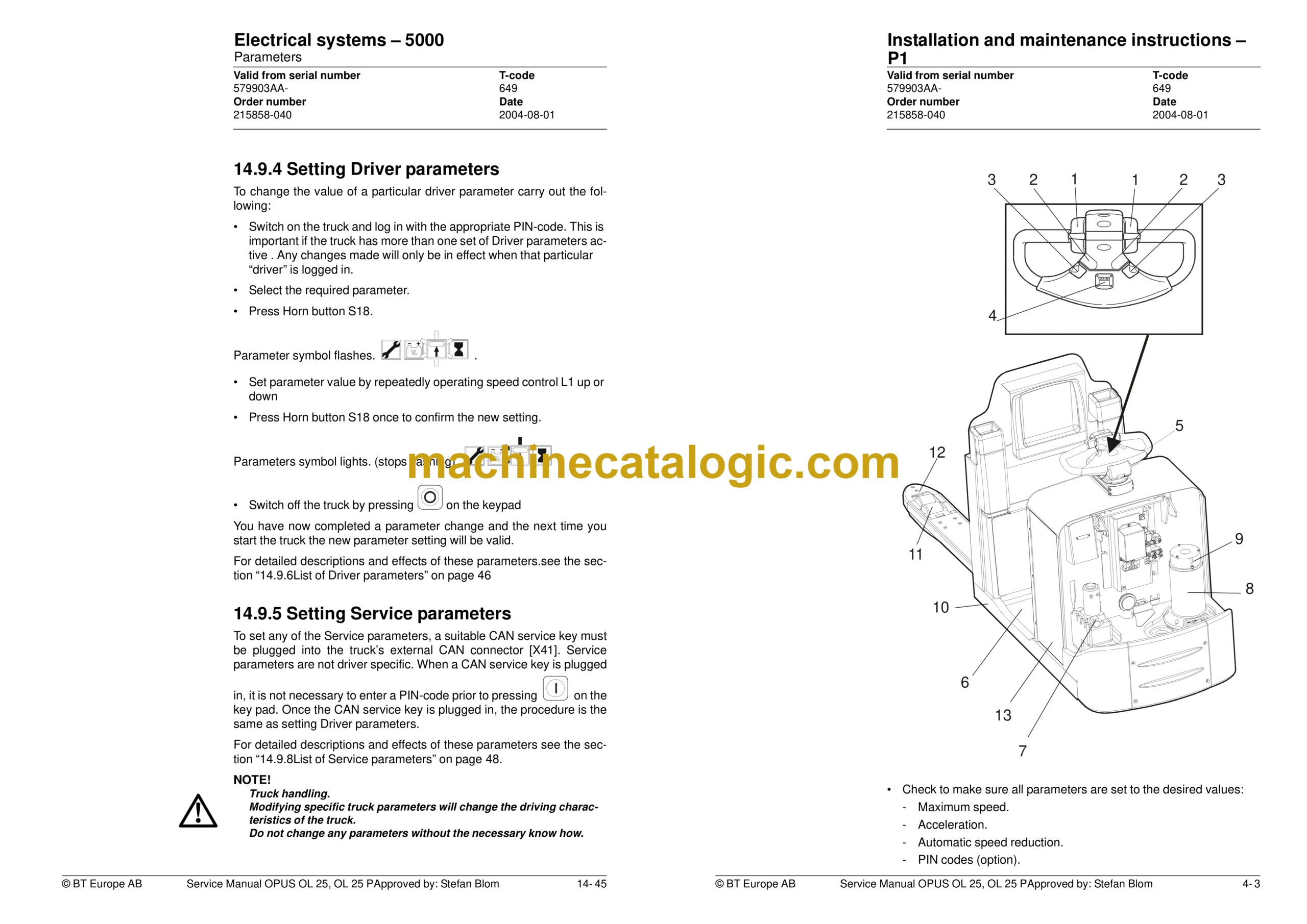
4- Installation and maintenance instructions – P1
4.1 Truck installation
4.2 Introduction, maintenance
4.3 Cleaning and washing
4.4 Safe lifting
5- Maintenance, lubrication schedule – P2
5.1 Test drive
5.2 Maintenance schedule
5.3 Lubrication schedule
6- Oil and lubricant specifications – P3
7- Tools – P4
7.1 Super Seal connectors
7.2 AMP connectors
7.3 Molex connectors
7.4 Other tools
8- Fork carriage – 0380
8.1 Included components
8.2 Disassembly of the fork carriage
8.3 Roller replacement
9- Electric drive motor – 1760
9.1 Included components
9.2 General
9.3 Mechanical design
9.4 Disassembly of the motor from the truck
9.5 Assembly of the motor in the truck
9.6 Service and repairs
9.7 Technical data
10- Driving unit/gear – 2550
10.1 Included components
10.2 Disassembly/Assembly Leakage from top cover
10.3 Replacing the drive axle jointing ring
10.4 Replacing the wheel bolt
11- Electromagnetic brake – 3370
11.1 Included components
11.2 Disassembly
11.3 Assembly
11.4 Manual release of the brake
11.5 Adjustment
12- Swivel wheel – 3540
12.1 General
12.2 Main component of swivel wheel
12.3 Maintenance
13- Electrical steering system – 4300
13.1 General
13.2 Electrical steering servo
13.3 Steering servo components
13.4 Adjustment
13.5 Steering unit
13.6 Disassembly/assembly of buttons
13.7 Replacing the potentiometer
13.8 Inspection and replacement of the steering unit’s steel belt (Ergo version)
13.9 Replacing the inductive brake sensor
13.10 Replacing the viscous damper
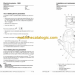
14- Electrical systems – 5000
14.1 Electrical equipment overview
14.2 Equipment list and electrical diagram
14.3 Extra I/O module
14.4 Functional description
14.5 Speed limitation
14.6 Hour meter and battery condition
14.7 Diagnostic and troubleshooting
14.8 Part numbers
14.9 Parameters
14.10 Technical specifications – Curtis 1243
15- Hydraulic system – 6000
15.1 OL 25
15.2 OL 25 P
16- Main lift chain system OL 25 P – 7120
16.1 General
16.2 Checking the chain setting
16.3 Chain inspection
16.4 Cleaning
16.5 Lubrication
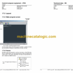
17- Control/computer equipment – 8700
17.1 General
17.2 Connection
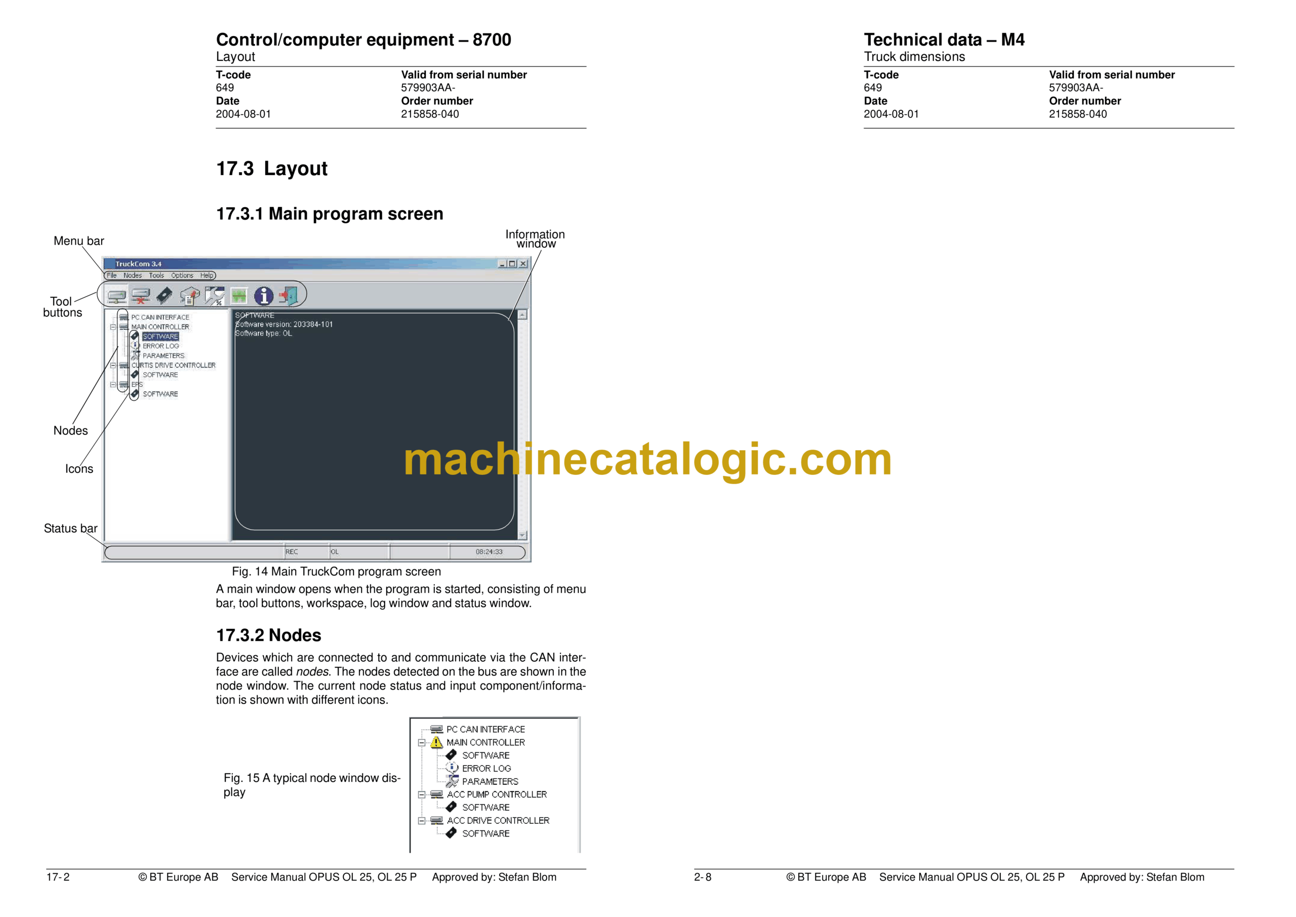
17.3 Layout
17.4 Connection function
17.5 Disconnection function
17.6 Downloading program function
17.7 Truck report function
17.8 Parameters function
17.9 Diagnostics function
17.10 Other menu functions
17.11 Specifications
17.12 Installation
18- Operator’s cabin, cabin lifting OL 25 P – 9130
18.1 General
18.2 Operator cabin details
18.3 Adjustment
18.4 Outer side guide


