Format: PDF (Printable Document)
File Language: English
File Pages: 320
File Size: 10.31 MB (Speed Download Link)
Brand: BT
Model: OSE100, OSE100W Order Picker
Type of Document: Repair Manual
$ 40
1. Contents
2. General introduction
2.1 How to use this manual
2.2 Warning symbols
2.3 Pictograms
3. General safety rules
3.1 Work safety
3.2 Electrical system
3.3 Safe lifting
3.4 Truck modifications
4. Operation and connection sequences
Symbols on keypad and display
4.1 Battery is connected
4.2 Logging in
4.3 Basic conditions for driving
4.4 Driving in fork direction
4.5 Driving in the drive wheel direction
4.6 Braking in neutral
4.7 Reverse braking
4.8 Brake operation via controls
4.9 Steering
4.10 Initial fork lift up
4.11 Initial fork lift down
4.12 Platform up
4.13 Platform down
5. Parameters, menu navigation and calibration
5.1 General
5.2 Parameter settings
5.3 Calibration
6. Installation and commissioning
6.1 Transporting the truck
6.2 Transporting the mast
6.3 Safe lifting
6.4 Battery installation
6.5 Using PIN codes
6.6 Setting parameters
6.7 Function check
7. Maintenance
7.1 Introduction
7.2 Maintenance instructions
7.3 Checking normal truck function
7.4 Safety check
7.5 First service
7.6 Maintenance schedule
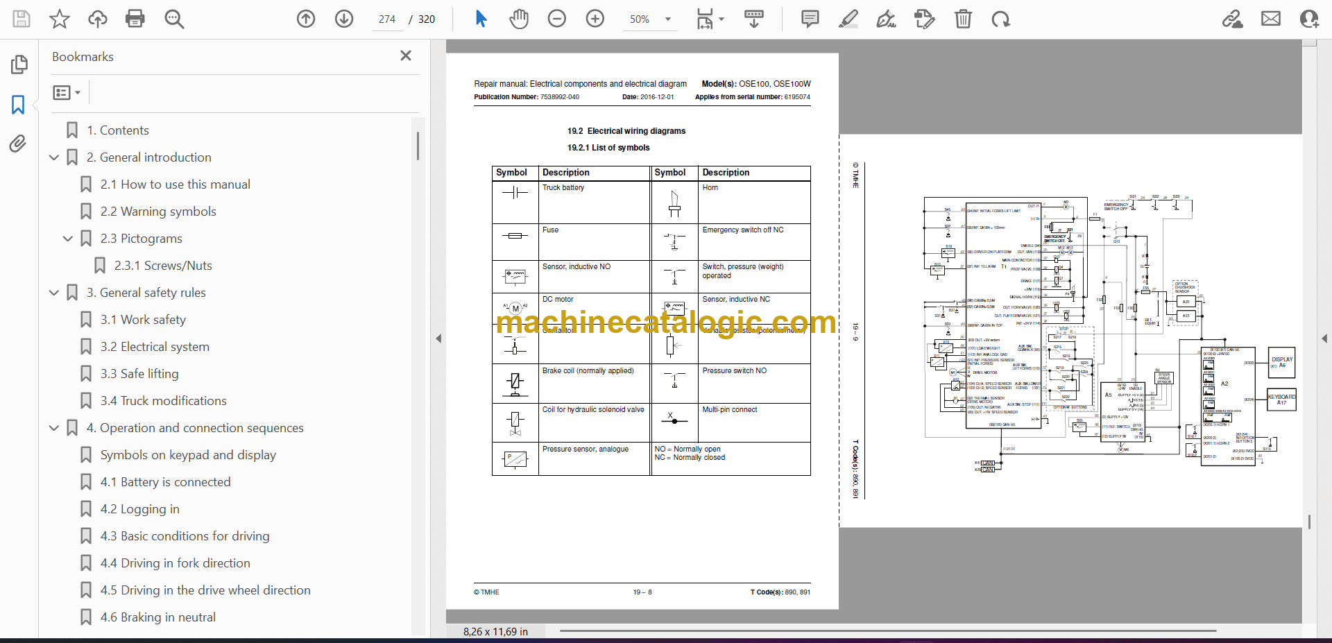
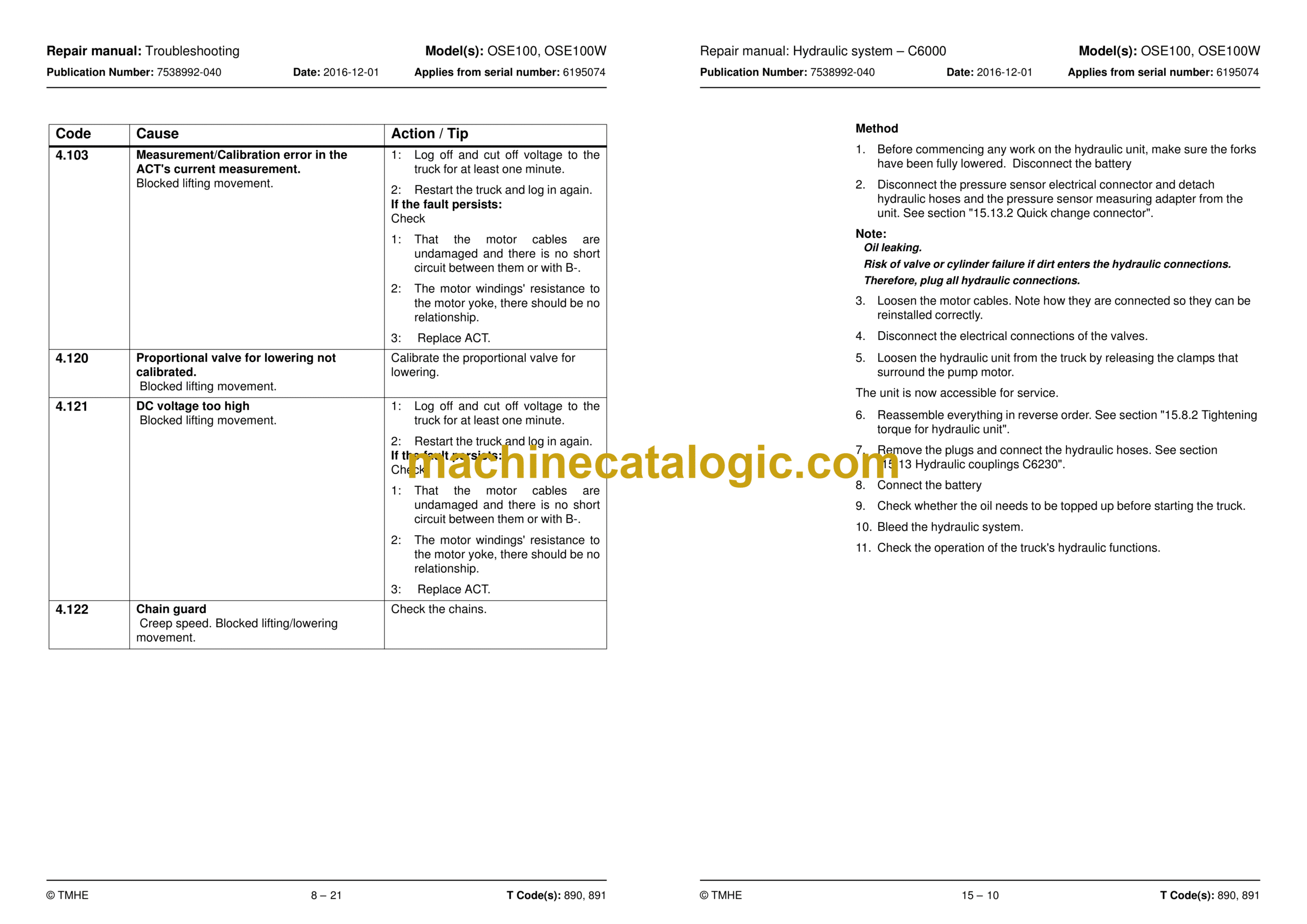
8. Troubleshooting
8.1 Towing a defective truck
8.2 Auxiliary functions
8.3 Error code system
8.4 Error codes
8.5 Built-in test function for the tiller arm
8.6 Built-in test function
8.7 Digital input/output status
9. Chassis – C0000
9.1 Signs, warnings, labels – C0850
10. Motors – C1700
10.1 Pump motor – C1710
10.2 Steering motor – C1730 (steering servo assembly)
10.3 Drive motor – C1760
11. Drive gear – C2000
11.1 General
11.2 Component overview – drive gear
11.3 Service and repairs with the drive gear in the truck
11.4 Repairs with transmission removed
12. Brake system/Wheels – C3000
12.1 General
12.2 Parking brake – C3370
12.3 Drive wheel – C3530
12.4 Support arm wheels – C3550
12.5 Wheel wear
13. Steering system – C4000
13.1 General
13.2 Component overview
13.3 Steering unit – C4110
13.4 Reference sensor – C4350
13.5 Steering bearing – C4380
14. Electrical system – C5000
14.1 Battery C5110
14.2 Contactor C5190
14.3 ACT/ACC regulators C5460
15. Hydraulic system – C6000
15.1 General
15.2 Hydraulic cleanliness
15.3 Component overview – Hydraulic system
15.4 Operating pressure
15.5 Pressure limiting valve
15.6 Hose rupture valve
15.7 Pressure sensor
15.8 Hydraulic unit – C6100
15.9 Removing/installing the hydraulic unit
15.10 Adjusting the pressure limiting valve
15.11 Hydraulic calibration
15.12 Hydraulic system, bleeding
15.13 Hydraulic couplings C6230
16. Mast/Lift system – C7000
16.1 Main lifting chain system C7120
16.2 Fork carriage – 7420
16.3 Fork carriage – 7420
16.4 Forks C7410
17. Option – C9000
17.1 Spider expansion unit
17.2 T.W.I.S Toyota Wireless Information System
17.3 E-bar
17.4 Overview
18. Instructions for disposal
18.1 General
18.2 Marking of plastics
18.3 Pressure vessels
18.4 Sorting categories
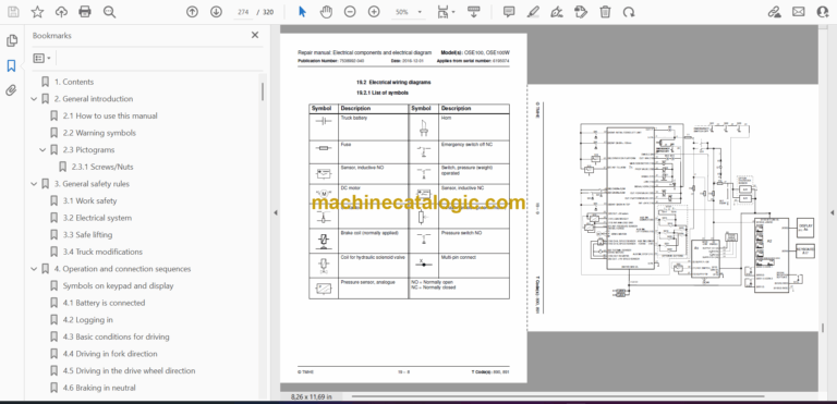
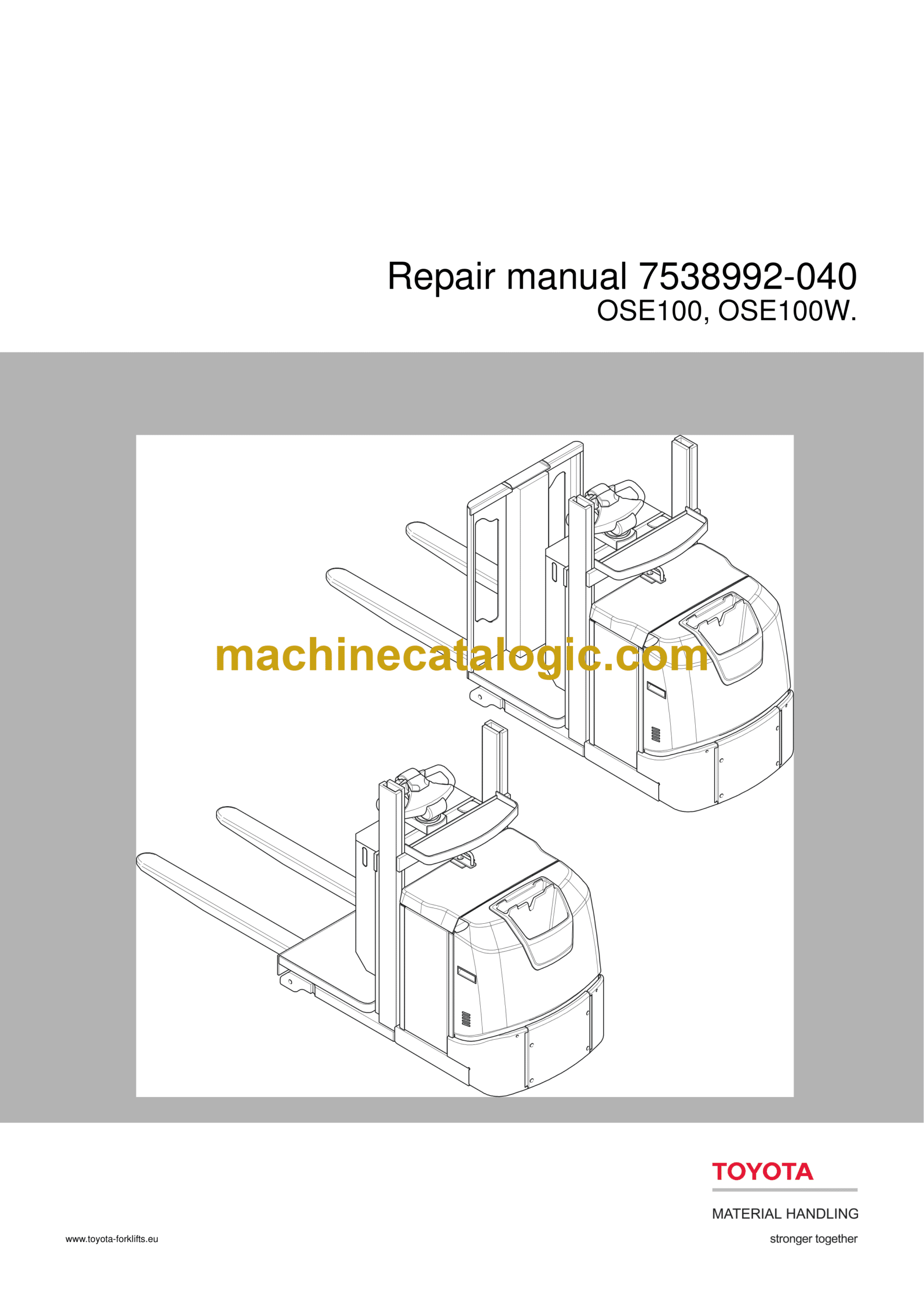
19. Electrical components and electrical diagram
19.1 Electric components
19.2 Electrical wiring diagrams
20. Hydraulics schematics
20.1 OSE100
20.2 OSE100W
21. Tools
21.1 Super Seal connectors
21.2 AMP connectors
21.3 AMP connectors, Multilock series 040
21.4 Molex connectors
21.5 CPC contacts
21.6 MQS contacts
21.7 Grease guns
21.8 Other tools
22. Service data and grease specifications
22.1 General tightening torques
22.2 Lubrication chart
22.3 Oil and grease specification
23. Technical data
23.1 Basic data
23.2 Speed limitation
