Format: PDF (Printable Document)
File Language: English
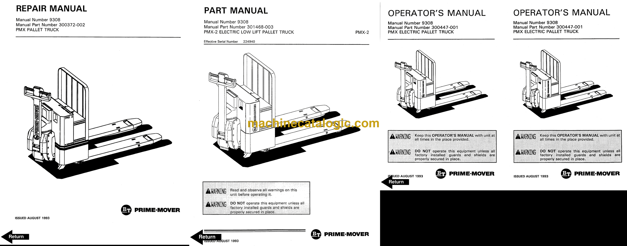
Brand: BT
Model: PMX-2 Powered Pallet Truck
Type of Document: Full Manual (Service, Parts and Operators Manual)
$ 70
Front Cover
Parts Ordering Instructions
Field Modifications
Safety Messages
Grease Points
Fill Points
Planned Maintenance Procedures
Adjustments
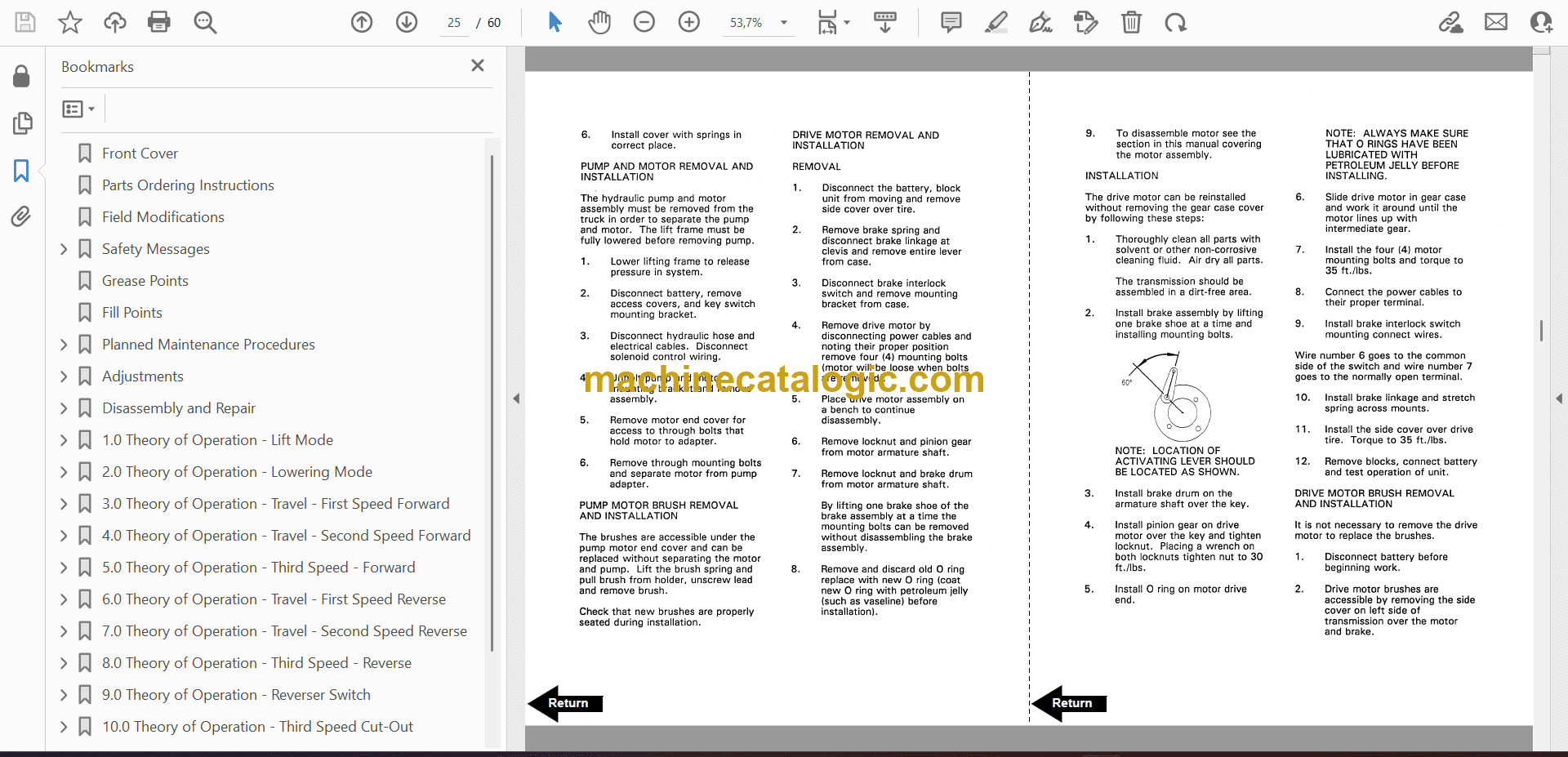
Disassembly and Repair
1.0 Theory of Operation – Lift Mode
2.0 Theory of Operation – Lowering Mode
3.0 Theory of Operation – Travel – First Speed Forward
4.0 Theory of Operation – Travel – Second Speed Forward
5.0 Theory of Operation – Third Speed – Forward
6.0 Theory of Operation – Travel – First Speed Reverse
7.0 Theory of Operation – Travel – Second Speed Reverse
8.0 Theory of Operation – Third Speed – Reverse
9.0 Theory of Operation – Reverser Switch
10.0 Theory of Operation – Third Speed Cut-Out
PMX Trouble Shooting Index
Battery Pack Schematic
Back Cover
Front Cover
Parts Ordering Instructions
Field Modifications
General Information
Alphabetical Index
Figure # 0.1 Decals and Parts List Assembly
Figure # 0.2 Parts List Index
Figure # 1.1 Handle and Transmission Installation
Figure # 1.2 Resistor Twist Control Handle Assembly
Figure # 1.3 Transistor Twist Control Handle Assembly
Figure # 1.4 Resistor Thumb Control Handle Assembly
Figure # 1.5 Transistor Thumb Control Handle Assembly
Figure # 1.6 Transmission Assembly
Figure # 2.1 Resistor Electrical Schematic
Figure # 2.2 Resistor Electrical Schematic Symbols
Figure # 2.3 Resistor Control Wiring Assembly
Figure # 2.4 Resistor Power Component Assembly
Figure # 2.5 Resistor Control Panel Assembly
Figure # 2.6 Resistor Forward and Rearward Contactor Assembly
Figure # 2.7 Resistor High Speed Contactor Assembly
Figure # 2.8 Transistor Electrical Schematic
Figure # 2.9 Transistor Electrical Schematic Symbols
Figure # 2.10 Transistor Control Wiring Assembly
Figure # 2.11 Transistor Power Component Assembly
Figure # 2.12 Transistor Control Panel Assembly
Figure # 2.13 Transistor Forward & Rearward Contactor Assembly
Figure # 2.14 Power Connector Assembly
Figure # 2.15 12 Volt, Drive Motor Assembly
Figure # 2.16 24 Volt, Drive Motor Assembly
Figure # 2.17 Pump Motor Assembly
Figure # 3.1 Hydraulic Schematic
Figure # 3.2 Hydraulic Schematic Symbols
Figure # 3.3 Hydraulic System Assembly
Figure # 3.4 Lift Cylinder Assembly & Cold Storage Lift Cylinder Assembly
Figure # 3.5 Hydraulic Pump and Motor Assembly
Figure # 4.1 Shielding Assembly
Figure # 4.2 Lift Frame and Carrier Frame Assembly
Figure # 5.1 Battery Pack
Figure # 5.2 Battery Pack Cable Assembly
Figure # 5.3 Battery Pack Connector Assembly
Figure # 5.4 Battery Blocks
Figure # 10.1 Special Tools and Lubrications
Numerical Index
Back Cover
Front Cover
Important Notice
Foreword
Table of Contents
Drive Safely
Introduction
Preliminary Service
Operator
Operating Practices
Data Plate and Decals
Controls and Equipment
Before Operation Inspection
Operation
Parking
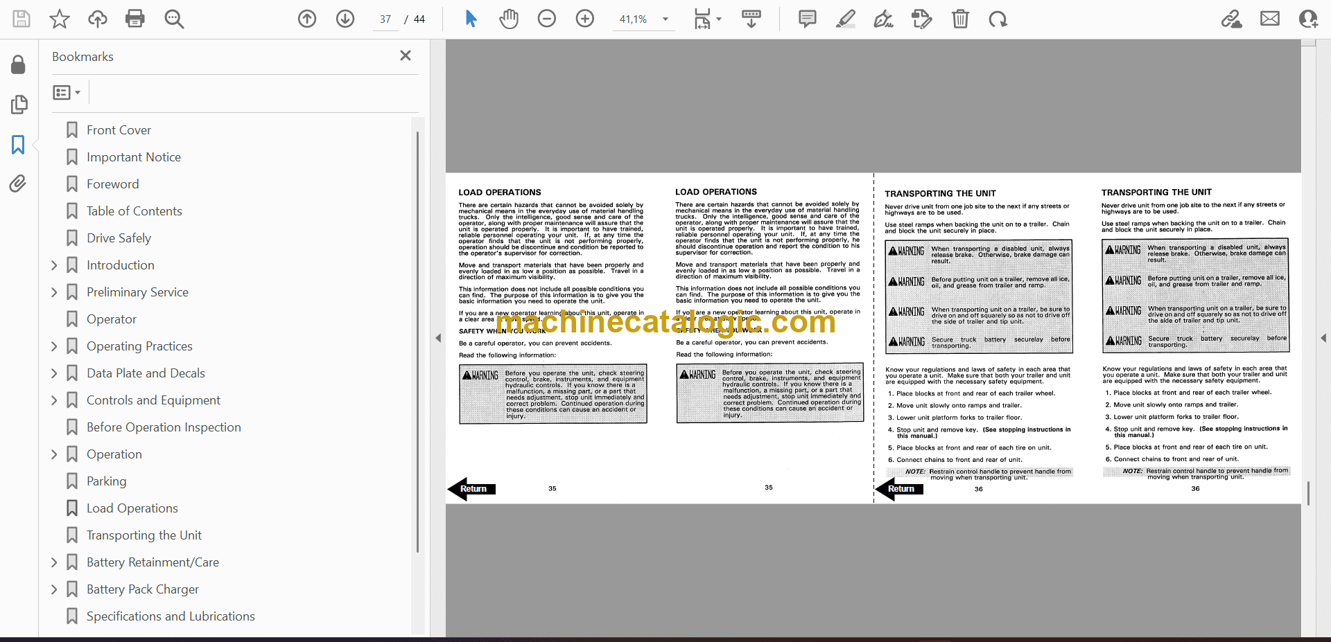
Load Operations
Transporting the Unit
Battery Retainment/Care
Battery Pack Charger
Specifications and Lubrications
Service Intervals
Field Modifications
Back Cover


