Format: PDF (Printable Document)
File Language: English
File Pages: 514
File Size: 20.40 MB (Speed Download Link)
Brand: BT
Model: Reflex RR B,E RR B,E CC
Part No: 713962- and 930971-
Type of Document: Master Service Manual
$ 40
1- Table of contents
2- General product information – M2
2.1 Presentation of the reach trucks
2.2 Truck data
2.3 Truck dimensions
2.4 Identification plate, truck
2.5 Main components RR B/E 1-8
2.6 Main components RR B/E 2-8 CC
2.7 Warning and information plates and symbols RR B/E 1-8
2.8 Warning and information plates and symbols RR B/E 2-8 CC
3- Technical data – M4
3.1 General tightening torque
4- Introduction, maintenance – P1
4.1 Safety regulations during maintenance work
4.2 Cleaning and washing
4.3 Safe lifting
4.4 Opening motor compartment
4.5 Cab tilting
5- Preventive maintenance – P2
5.1 Maintenance Schedule
6- Oil and grease specification – P3
7- Tools – P4
7.1 Super Seal connector
8- Cab heating/ventilation – 0630
8.1 General
8.2 Air conditioning unit
9- Driver protection – 0840
9.1 General
9.2 Tilt Stops
10- Electric pump motor -1710
10.1 General
10.2 Dismantling the pump motor
10.3 Dismantling and assembling the pump motor
10.4 Bearing replacement
10.5 Installation instructions for external temperature sensor
11- Electric steering motor – 1730
11.1 General
11.2 Replacing the steering motor
11.3 Dismantling and assembling the carbon brushes
12- Electric drive motor – 1760
12.1 General
12.2 Dismantling the drive motor
12.3 Dismantling and assembling the drive motor
12.4 Bearing replacement
12.5 Installation instructions for external temperature sensor
13- Mechanical drive gear unit – 2550
13.1 General
13.2 Components/data for the drive assembly/transmission
13.3 Replacing the drive motor/drive transmission
13.4 Checking/replacing the oil
13.5 Repairs
14- Travel brake system – 3100.1
Without support arm brakes
14.1 General
14.2 Operating description
14.3 Electromechanical disc brake, drive motor
14.4 Maintenance
15- Travel brake system – 3100.2
With support arm brake
15.1 General
15.2 Operating description
15.3 Electromechanical disc brake, drive motor
15.4 Maintenance
15.5 Multiple disc brake, support arm
15.6 Maintenance
16- Drive wheel – 3530
16.1 General
16.2 Dismantling the drive wheel
16.3 Assembling the drive wheel
17- Fork/support arm wheel – 3550.1
17.1 General
17.2 Dismantling the wheel
17.3 Assembling the wheel
17.4 Dismantling/assembling the wheel bearings
18- Fork/support arm wheel – 3550.2
18.1 General
18.2 Dismantling the wheel
18.3 Assembling the drive wheel
18.4 Dismantling the wheel bearing
18.5 Assembling the wheel bearing
19- Mechanical steering system – 4100
19.1 General
19.2 Replacing the steering generator
20- Steering angle sensor – 4350
20.1 General
20.2 Procedure
21- Electrical system – 5000
21.1 General
21.2 Symbol list and wiring diagrams
21.3 Component list
21.4 Functional description
22- Battery – 5110
22.1 Battery dimensions
22.2 Setting the battery parameters on RR trucks fitted with Hawker Evolution gel batteries
23- Transistor panel – 5460
23.1 Frequency converter
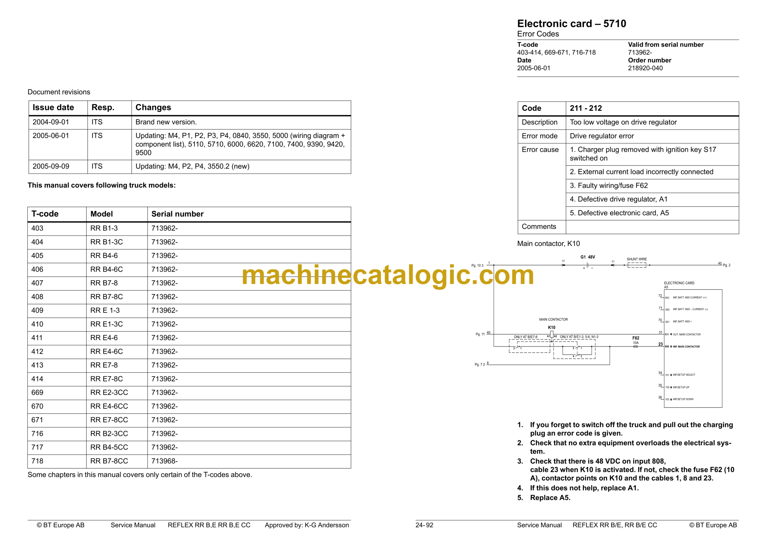
24- Electronic card – 5710
24.1 General description
24.2 Terminal connections and voltages on A5
24.3 Adjusting the lowering speed
24.4 Displaying and programming
24.5 Parameter setting of all parameters
24.6 Operating hours
24.7 Warning codes
24.8 Error Codes
24.9 Warning Codes without registration
24.10 Warning codes with registration
24.11 Error Codes
25- Keypad
25.1 General
25.2 Display
25.3 Function
25.4 Programming
26- Hydraulics – 6000
26.1 General
26.2 Symbols
26.3 List of symbols
26.4 Adjusting fork lowering
26.5 Adjusting the maximum lifting capacity
27- Hydraulic pump – 6140
27.1 General
27.2 Replacing the hydraulic pump
28- Hydraulic connections – 6230
28.1 General
28.2 Tightening torque for hydraulic connections
29- Mast mounted hose reel – 6370
29.1 General
29.2 Assembling
29.3 Check after assembly
30- Main lift cylinder – 6610
30.1 General
30.2 Tools
30.3 Dismantling the lift cylinders from the mast
30.4 Dismantling the cylinder
30.5 Assembling the cylinder
31- Free lift cylinder – 6620
31.1 General
31.2 Tools
31.3 Dismantling
31.4 Dismantle the rod seal and support ring
31.5 Dismantling the piston
31.6 Dismantling and assembling the hose rupture valve
31.7 Assembling the cylinder
31.8 Assembly
32- Reach cylinder – 6650
32.1 General
32.2 Assembling and dismantling the reach cylinder
32.3 Dismantling
32.4 Assembling
33- Tilt cylinder – 6660.1
33.1 General
33.2 Mast with valve on the fork carriage
33.3 Mast without valve on the fork carriage
34- Tilt cylinder – 6660.2
34.1 General
34.2 Dismantling the cylinder from the truck
34.3 Dismantling and assembling the cylinder
34.4 Refitting the cylinder in the truck
35- Main mast -7100
35.1 General
35.2 List of tools
35.3 Transporting the truck
35.4 Assembling the mast
35.5 Dismantling the mast
35.6 Adjusting the play
35.7 Assembly
36- Main lift chain system – 7120
36.1 General
36.2 Checking the chain setting
36.3 Chain inspection
36.4 Cleaning
36.5 Lubrication
37- Lifting devices – 7400
37.1 General
37.2 Checking the fork carriage’s wearing strips
37.3 Fork spread unit
37.4 Telescopic forks
37.5 Maintenance
37.6 Troubleshooting
37.7 Extended forks
38- Battery charger – 8340
38.1 General
38.2 Installation
38.3 Functional description
38.4 Service and maintenance
39- Control/computer equipment – 8700
39.1 General
39.2 Connection
39.3 Layout
39.4 Function for connection
39.5 Function for disconnecting
39.6 Function for program downloading
39.7 Function for truck report
39.8 Function for parameters
39.9 Function for diagnostics
39.10 Other menu functions
39.11 Specifications
39.12 Installation
40- Extra warning lights/alarm – 9370
40.1 General
41- Positioning equipment – 9390
41.1 General
41.2 Height indication
41.3 Function
41.4 Display
41.5 Height pre-set
41.6 Function
41.7 Display
41.8 Assembly of height pre-set
41.9 Programming
41.10 Automatic driving
41.11 Parameters
41.12 Programming parameters
41.13 Error codes
42- TV equipment – 9390
42.1 General
42.2 Camera mounted on fork
43- Truck log system, code lock – 9420
43.1 General
43.2 SD 16
43.3 Components
43.4 I/O Module
44- Extra equipment – 9500
44.1 Dry powder extinguisher
45- Instructions for destruction
45.1 General
45.2 Procedure
45.3 Abbreviations
45.4 Sorting
45.5 Frame/chassis (0300)
45.6 Operator’s seat, cushion (0620)
45.7 Cab heating/ventilation (0630)
45.8 Driver controls (0640)
45.9 Interior fittings RR-B (0680)
45.10 Interior fittings RR-E (0680)
45.11 Interior fittings RR-B-CC (0680)
45.12 Interior fittings RR-E-CC (0680)
45.13 Rollover guard/head guard (0810)
45.14 Finger protectors (0820)
45.15 Finger/foot protectors (0820)
45.16 Finger/foot protectors (0820)
45.17 Electric motors (1700)
45.18 Electric fan motor (1740)
45.19 Drive unit, final gear (2500)
45.20 Wheels (3500)
45.21 Electric steering system (4300)
45.22 General electric equipment (5100)
45.23 Manöversystem, körfunktion (5300)
45.24 Power system, drive function (5400)
45.25 Control system, operation function (5500)
45.26 Steering/protective electronics (5700)
45.27 Hydraulic unit (6100)
45.28 Hydraulic system, fitted on the chassis (6200)
45.29 Hydraulic system, fitted on the mast (6300)
45.30 Hydraulcylindrar (6600)
45.31 Main mast (7100)
45.32 Lift fork (7410)
45.33 Optional electric equipment (9300)
45.34 Radio/CD player (9330)
45.35 Extra work light (9360)
45.36 Optional electric equipment (9400)
45.37 Optional electric equipment (9400)


