Format: PDF (Printable Document)
File Language: English
File Pages: 711
File Size: 22.97 MB (Speed Download Link)
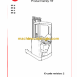
Brand: BT
Model: RR N, RR B, RR E, RR M
Part No: 171522-040
Type of Document: Master Service Manual
$ 40
Contents Master Service Manual (MSM)
1 Document list
Introduction to BT’s Service Manual
Contents, M
1 Truck information
Operator’s manual
1 General
1.1 Issued operator’s manuals
2 Year of introduction
General product information
1 Presentation of BT’s reach trucks
1.1 Application areas for BT’s reach trucks
1.2 Prohibited applications for BT’s reach trucks
2 Truck data
3 Truck dimensions
4 Identification plate, truck
5 Capacity plate
6 Modification plate
7 Identification plate, mast
8 Main components
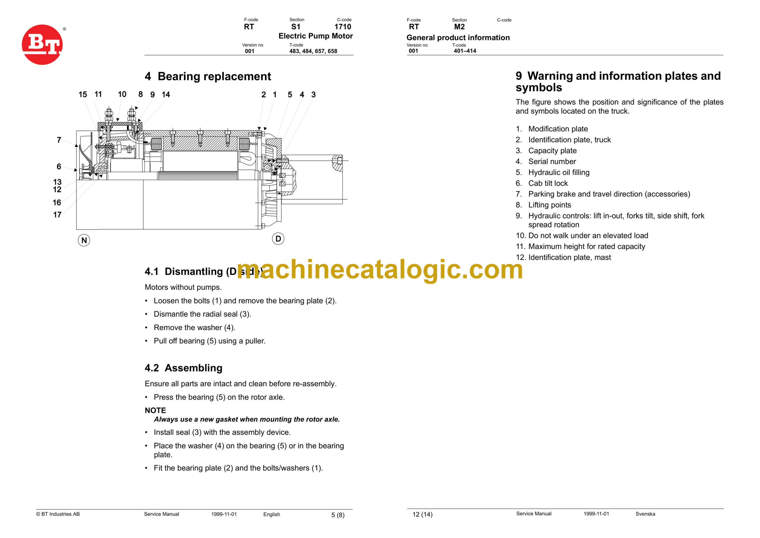
9 Warning and information plates and symbols
General product information
1 Presentation of BT’s reach trucks
1.1 Application areas for BT’s reach trucks
1.2 Prohibited applications for BT’s reach trucks
2 Truck data
3 Truck dimensions
4 Identification plate, truck
5 Capacity plate
6 Modification plate
7 Identification plate, mast
8 Main components
9 Warning and information plates and symbols
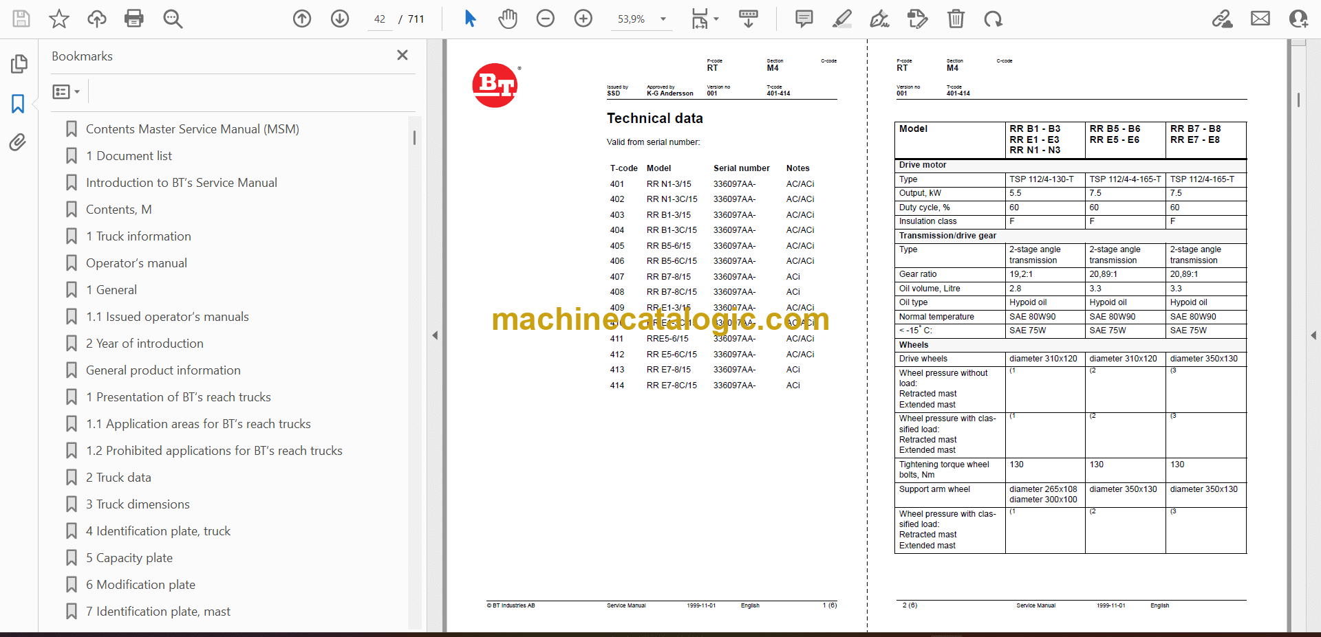
Technical data
Technical data
Instructions for destruction
2 Procedure
3 Abbreviations
4 Sorting
2 Dismantling
3 Material handling
2 Dismantling
3 Material handling
2 Dismantling
3 Material handling
2 Dismantling
3 Material handling
2 Dismantling
3 Material handling
2 Dismantling
3 Material handling
2 Dismantling
3 Material handling
2 Dismantling
3 Material handling
2 Dismantling
3 Material handling
2 Dismantling
3 Material handling
2 Dismantling
3 Material handling
2 Dismantling
3 Material handling
2 Dismantling
3 Material handling
2 Dismantling
3 Material handling
2 Dismantling
3 Material handling
2 Dismantling
3 Material handling
2 Dismantling
3 Material handling
2 Dismantling
3 Material handling
2 Dismantling
3 Material handling
2 Dismantling
3 Material handling
2 Dismantling
3 Material handling
2 Dismantling
3 Material handling
2 Dismantling
3 Material handling
2 Dismantling
3 Material handling
2 Dismantling
3 Material handling
2 Dismantling
3 Material handling
Quality Parts
1 Issued Quality Parts
Recommended Spare Parts (RSP)
1 Issued RSP
Contents, P
1 Preventive Maintenance
Introduction, maintenance
1 Safety regulations with maintenance work
2 Cleaning and washing
2.1 External cleaning
2.2 Cleaning the motor compartment
2.3 Electrical components
3 Safe lifting
4 Tilting the cab
Preventive Maintenance
1 Maintenance schedule
Preventive Maintenance
1 Maintenance schedule
Oil and grease specification
Tools
Contents, S
1 Service instructions
Cab heating/ventilation
1 General
2 Air conditioning
2.1 Ventilation
2.2 Main heater
2.3 Auxiliary heater
2.4 Temperature
2.5 Air direction
2.6 Fuses
Emergency exit (12)
2.7 Lighting
3 Circuit diagram
4 List of components
Driver Protection
1 General
2 Tilt Stops
2.2 Removing the tilt stops
Electric pump motor
2 Dismantling the pump motor
3 Dismantling and assembling the pump motor
3.2 Truck with tilting cabs
3.3 Dismantling
3.4 Assembling
3.5 Truck with tilting cabs
3.6 Trucks without tilting cabs
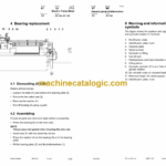
4 Bearing replacement
4.1 Dismantling
4.2 Assembling
5 Installation instructions for external temperature sensor
Electric Pump Motor
1 General
2 Dismantling the Pump Motor
2.1 Connection
3 Removing and Replacing the Pump Motor
3.1 Dismantling
3.2 Assembling
4 Bearing replacement
4.1 Dismantling (D side)
4.2 Assembling
4.3 Dismantling (N side)
4.4 Assembling (N side)
4.5 Carbon brushes and brush holders
4.5.2 Commutator
4.5.3 Machining the commutator
Electric Steering Motor
1 General
2 Replacing the Steering Motor
2.2 Truck with tilting cabs
2.3 Dismantling
2.4 Assembling
3 Removing and Replacing the Carbon Brushes
3.1 Trucks with Tilting Cabs, Cold Store
3.2 Trucks without Tilting Cabs
Electric drive motor
1 General
2 Dismantling the drive motor
3 Dismantling and assembling the drive motor
3.2 Truck with tilting cabs
3.3 Dismantling the drive motor
3.3.1 Removing the gear wheel
3.3.2 Removing the brakes
3.4 Assembling the drive motor
3.4.2 Assembling the gear wheel
3.5 Truck with tilting cabs
3.6 Trucks without tilting cabs
4 Bearing replacement
4.1 Dismantling
4.1.2 D-side
4.2 Assembling
4.2.1 N-side
4.2.2 D-side
5 Installation instructions for external temperature sensor
Mechanical drive gear unit
1 General
2 Components/data for the drive assembly/transmission
2.1 Component placement
2.2 Technical data
2.3 Dismantling the transmission
3 Replacing the drive motor/drive transmission
3.2 Dismantling the drive transmission
3.3 Assembling the transmission
3.4 Installing the drive motor
3.4.1 Assembling the gear wheel
4 Checking/replacing the oil
4.1 Checking/refilling the oil
4.2 Changing the Oil
5 Repairs
5.1 Replacing the drive shaft sealing ring
5.1.1 Dismantling
5.1.2 Assembling
5.2 Leakage from the upper cover
5.3 Leakage from the lower cover
5.4 Replacing wheel bolts
Travel brake system
1 General
2 Operating description
2.1 Releasing the accelerator
2.2 Travel direction selector
2.3 Pressing down the brake pedal
2.4 Parking brake
2.5 Emergency brake
3 Electromechanical disc brake, drive motor
3.1 Assembling
3.2 Dismantling
3.3 Inspection
3.4 Assembling
4 Maintenance
4.1 Adjusting the play
4.2 Wear
4.3 Check the braking force
Travel brake system
1 General
2 Operating description
2.1 Releasing the accelerator
2.2 Travel direction selector
2.3 Pressing down the brake pedal
2.4 Parking brake
2.5 Emergency braking
3 Electromechanical disc brake, drive motor
3.1 Assembling
3.2 Dismantling
3.3 Inspection
3.4 Assembling
4 Maintenance
4.1 Adjusting the play
4.2 Wear
4.3 Check the braking force
5 Multiple disc brake, support arm
5.1 Assembling
5.2 Dismantling
5.3 Inspection
5.4 Assembling
6 Maintenance
6.1 Adjusting the play
Drive wheel
1 General
2 Dismantling the drive wheel
3 Assembling the drive wheel
Fork/support arm wheel
1 General
2 Dismantling the wheel
3 Assembling the wheel
4 Dismantling/assembling the wheel bearings
4.1 265 mm wheel and 300 mm wheels without brakes.
4.1.1 Dismantling the bearing
4.1.2 Assembling the bearing
4.2 300 mm wheel with brake and 350 mm wheel
4.2.1 Dismantling the bearing
4.2.2 Assembling the bearing
Fork/support arm wheel
1 General
2 Dismantling the wheel
3 Assembling the drive wheel
4 Dismantling the wheel bearing
5 Assembling the wheel bearing
Mechanical steering system
1 General
2 Replacing the steering generator
2.1 Dismantling
2.2 Assembling
Steering angle sensor
Applies to:
2 Procedure
2.2 Adjustment of the steering angle sensor
Electrical system
1 General
1.1 Electrical panel
2 Symbols and electrical diagrams
2.1 List of symbols
2.2 Electrical diagram 1/11
2.3 Electrical diagram 2/11
2.4 Electrical diagram 3/11
2.5 Electrical diagram 4/11
2.6 Electrical diagram 5/11
2.7 Electrical diagram 6/11
2.8 Electrical diagram 7/11
2.9 Electrical diagram 8/11
2.10 Electrical diagram 9/11
2.11 Electrical diagram 10/11
2.12 Electrical diagram 11/11
2.13 List of components
2.14 Diagram 1
2.15 Diagram 2
2.16 Diagram 3
2.17 Diagram 4
2.18 Diagram 5
2.19 Diagram 6
2.20 Diagram 7
2.21 Diagram 8
3 Description of function
3.1 Ignition key in the 0 position
3.2 Ignition key in 1 position
3.3 Selection of travel direction
3.3.1 With the steering console
3.3.2 With the left-hand handle
3.3.3 With the speed control
3.4 Driving
3.5 Steering
3.6 Steering wheel indicator
3.7 Braking
3.7.1 Auto plug braking
3.7.2 Motor brake (electric)
3.7.3 Foot brake
3.7.4 Parking brake
3.8 Fork lift
3.9 Maximum height
3.10 Maximum height
3.11 Fork lowering
3.12 Mast out/in
3.13 Fork tilt up/down
3.14 Hydraulic function 4
3.15 Hydraulic function 5
3.16 Cabin tilt
3.17 Height indication
3.18 Height selection
3.19 Weight measurement
3.20 Operator – ID
3.20.1 With pin code
3.20.2 With pin code
Electrical System
1 General
2 Symbol List and Electrical Diagrams
2.2 Electrical diagram (1/9)
2.3 Electrical diagram (2/9)
2.4 Electrical diagram (3/9)
2.5 Electrical diagram (4/9)
2.6 Electrical diagram (5/9)
2.7 Electrical diagram (6/9)
2.8 Electrical diagram (7/9)
2.9 Electrical diagram (8/9)
2.10 Electrical diagram (9/9)
2.11 Component List
2.12 Figure 1
2.13 Figure 2
2.14 Figure 3
2.15 Figure 4
2.16 Figure 5
2.17 Figure 6
2.18 Figure 7
2.19 Figure 8
3 Functional Description
3.1 Key in Position 0
3.2 Key in Position I
3.3 Choice of travel direction
3.3.1 On the control console
3.3.2 On the accelerator
3.4 Driving
3.5 Steering
3.6 Steering wheel indicator
3.7 Braking
3.7.1 Auto-brakes
3.7.2 Motor brakes (electric)
3.7.3 Foot brakes
3.7.4 Parking brake
3.8 Fork lifting
3.9 Maximum Height
3.10 Fork lowering
3.11 Mast out/in
3.12 Fork tilt up/down
3.13 Hydraulic function 4
3.14 Hydraulic function 5
3.15 Driver identification
3.15.1 Without pin code
3.15.2 With pin code
Battery
1 Battery dimensions
Transistor panel
1 Frequency converter
1.2 Terminal connections and pole bolts
1.3 Technical Data
1.4 Installation of New Frequency Converter on Truck
1.5 Programming
Power electronics panel
1 General description
1.1 Terminal connections and pole bolts
1.2 Technical Data
1.3 Installing a new transistor panel
2 Parameter
3 Diagnostics and trouble shooting
3.1 Displaying error codes, logging errors
3.2 Error codes, trouble shooting
3.3 Resetting an error
4 Maintenance
4.1 Safety
4.2 Cleaning
5 Hand terminal 1307
6 Using the hand terminal
6.1 Check and adjust parameters
6.1.1 Use MORE INFO in PROGRAM MODE
6.2 SPECIAL PROGRAM MODE
6.3 Using TEST mode
6.4 Using DIAGNOSTICS MODE
6.5 SPECIAL DIAGNOSTICS MODE
Electronic card
1 General description
2 Terminal connections and voltages on A5
2.1 10X
2.2 20X
2.3 30X
2.4 40X
2.5 50X
2.6 60X
2.7 70X
2.8 80X
2.9 90X
3 Adjusting the lowering speed
4 Show
5 Programming
5.2 Driver parameters (1-7)
6 Warning Codes
7 Error Codes
7.1 Error mode
7.2 Safety logic
7.3 Warning Codes without registration
8 Warning codes with registration
9 Error Codes
9.1 Error codes with registration
10 Operating Time
11 Parameter Settings
11.1 Parameter 1
11.2 Parameter 2
11.3 Parameter 3
11.4 Parameter 4
11.5 Parameter 5
11.6 Parameters 6 and 7
11.7 Parameter 10
11.8 Parameter 11
11.9 Parameter 12
11.10 Parameters 13 to 14
11.11 Parameters 15 and 16
11.12 Parameters 17 and 18
11.13 Parameter 19
11.14 Parameter 20
11.15 Parameter 21
11.16 Parameter 22
11.17 Parameter 23
11.18 Parameter 24
11.19 Parameter 25
11.20 Parameter 26
11.21 Parameter 27
11.22 Parameter 28
11.23 Parameter 29
11.24 Parameter 37
11.25 Parameter 38
11.26 Parameter 39
11.27 Parameters 40 to 42
11.28 Other parameters
11.29 Installing a new card in the truck
Electronic card
1 General description
2 Terminal connections and voltages on A5
2.1 10X
2.2 20X
2.3 30X
2.4 40X
2.5 50X
2.6 60X
2.7 70X
2.8 80X
2.9 90X
3 Adjusting the lowering speed
4 Show
5 Programming
5.2 Driver parameters (1-7)
6 Warning Codes
7 Error Codes
7.2 Safety logic
7.3 Warning Codes without registration
8 Warning codes with registration
9 Error Codes
9.1 Error codes with registration
10 Running Time
11 Parameter Settings
11.1 Parameter 1
11.2 Parameter 2
11.3 Parameter 3
11.4 Parameter 4
11.5 Parameter 5
11.6 Parameter 10
11.7 Parameter 11
11.8 Parameter 12
11.9 Parameters 13 to 14
11.10 Parameters 15 and 16
11.11 Parameter 20
11.12 Parameter 21
11.13 Parameter 23
11.14 Parameter 24
11.15 Parameter 25
11.16 Parameter 26
11.17 Parameter 27
11.18 Parameter 28
11.19 Parameter 38
11.20 Parameter 39
11.21 Parameters 40 to 42
11.22 Other parameters
11.23 Installing a new card in the truck
Hydraulic system
1 General
2 Symbols
2.2 Hydraulic chart 2 (4)
2.3 Hydraulic chart 3 (4)
2.4 Hydraulic chart 4 (4)
3 List of symbols
3.2 Component placement 2 (3)
3.3 Component placement 3(3)
4 Adjusting fork lowering
5 Setting the maximum lifting capacity
Hydraulic system
1 General
2 Symbols
2.1 Hydraulic chart 1 (3)
2.2 Hydraulic chart 2 (3)
2.3 Hydraulic chart 3 (3)
3 List of symbols
3.1 Component placement 1 (2)
3.2 Component placement 2 (2)
4 Adjusting fork lowering
5 Setting the max lifting capacity
Hydraulic pump
1 General
2 Replacing the hydraulic pump
2.1 Dismantling
2.2 Assembling
Mast mounted hose reel
1 General
2 Assembling
3 Check after assembly
Hydraulic cylinder
1 General
2 Duplex mast
2.2 Dismantling the cylinder
2.3 Dismantling the rod seal, guide ring, guide ring holder and locking ring in lift cylinder
2.4 Assembling the locking ring, rod seal, guide ring and guide ring holder in the lift cylinder
2.5 Dismantling and assembling the lower brake valve
2.6 Assembling the cylinder
2.7 Assembling the cylinder in the mast
3 Triplex mast
3.1 Dismantling the free lift cylinder from the mast
3.2 Dismantling the mast lift cylinders from the mast
4 Cylinder seals
5 Replacing wear parts in the cylinder
5.2 Dismantling the cylinder
5.3 Replacing the lower support ring
5.4 Replacing the O-ring on the top sleeve
5.5 Replacing the internal wear parts in the top sleeve
5.6 Assembling the cylinder
5.7 Assembling the free lift cylinder in the mast
5.8 Assembling the mast lift cylinder
Main lift cylinder
1 General
2 Tools
3 Dismantling the lift cylinders from the mast
4 Dismantling the cylinder
4.1 Dismantling the rod seal, guide ring, guide ring holder and locking ring in lift cylinder
4.2 Fit the locking ring, rod seal, guide ring and guide ring holder in the lift cylinder
4.3 Dismantling and assembling the hose rupture valve
5 Assembling the cylinder
5.1 Assembling the cylinder in the mast
Free lift cylinder
1 General
2 Tools
3 Dismantling
3.1 Dismantling the cylinder
4 Dismantle the rod seal and the support ring.
4.1 Assembling the rod seal and the support ring.
5 Dismantling the ram
5.1 Assembling the ram in the free lift cylinder
6 Dismantling and assembling the hose rupture valve
7 Assembling the cylinder
8 Assembling
Reach cylinder
1 General
2 Assembling and dismantling the reach cylinder
3 Dismantling
3.1 Dismantling the cylinder
3.2 Dismantle the rod seal and the support ring.
3.3 Assembling the rod seal and the support ring.
3.4 Dismantling the ram
3.5 Assembling the ram
3.6 Assembling the cylinder
4 Assembling
Reach cylinder
1 General
2 Assembling and dismantling the reach cylinder
2.1 Dismantling the cylinder
2.2 Dismantling the rod
2.3 Dismantle the to sleeve seals.
2.4 Assembling the top sleeve
2.5 Fit the ram seal
2.6 Dismantling the rod
2.7 Assembling the cylinder
3 Assembling
Tilt cylinder
1. General
2 Mast with valve on the fork carriage
2.2 Dismantling the cylinder
2.3 Dismantling the rod seal
2.4. Dismantling the ram
2.5 Assembling the ram
2.6 Assembling the rod seal
2.7 Assembling the cylinder
2.8 Assembling the fork carriage
3 Mast without valve on the fork carriage
3.1 Dismantling the fork carriage
3.2 Dismantling the cylinder
3.3 Dismantling the rod seal
3.4 Dismantling the ram
3.5 Assembling the ram
3.6 Assembling the rod seal
3.7 Assembling the cylinder
3.8 Assembling the fork carriage
Tilt cylinder
1. General
2. Dismantling the cylinder from the truck
3. Dismantling and assembling the cylinder
3.1. Dismantling the cylinder
3.2. Dismantle the seals and the support ring
3.3. Assembling the rod seal and the support ring
3.4. Dismantling the ram
3.5. Assembling the ram
3.6. Assembling the cylinder
4. Refitting the cylinder in the truck
Tilt cylinder
1 General
2 Assembling and dismantling the tilt cylinder
2.2 Dismantling the rod
2.3 Dismantling the ram seals
2.4 Dismantle the top sleeve seals
2.5 Assembling the top sleeve
2.6 Assembling the ram seal
2.7 Dismantling the rod
2.8 Assembling the cylinder
3 Assembling
Main mast
1 General
2 List of tools
3 Transporting the truck
4 Assembling the mast
5 Dismantling the mast
6 Adjust the play
6.1 Adjusting the mast play.
6.1.1 Lateral play
6.2 Radial play
7 Assembling
Main mast
1 General
2 List of tools
3 Transporting the truck
4 Assembling the mast
5 Dismantling the mast
5.1 Chains, cylinders and hoses
5.2 Dismantling the runner
5.3 Inner guide
6 Assembling Duplex mast
6.2 Inner guide
6.3 Chains, cylinders and hoses
6.4 Fork carriage
6.5 Docking the mast in the truck
7 Assembling the Triplex mast
7.2 Inner guide
7.3 Chains, cylinders and hoses
7.4 Fork carriage
Main mast
1 General
2 List of tools
3 Transporting the truck
4 Assembling the mast
5 Dismantling the mast
6 Adjust the play
6.1 Adjusting the mast play.
6.1.1 Lateral play
6.2 Radial play
7 Assembling
Main lift chain system
1 General
2 Checking the chain setting
3 Chain inspection
3.1 Noise
3.2 Surface rust
3.3 Rusty links
3.4 Stiff links
3.5 Bolt rotation
3.6 Loose bolts
3.7 Outline wear
3.8 Stretching
3.9 Damage
3.10 Damaged discs
3.11 Damaged bolts
3.12 Dirty chain
4 Cleaning
5 Lubrication
Battery charger
1 General
2 Installation
3 Functional description
3.2 Charging process
3.3 Shutdown conditions
3.4 Delayed power on and charging
3.5 Extra charging
3.6 Equalised charging
3.7 Current and voltage characteristics
3.8 Safety shutdowns
3.9 Display and keyboard
3.9.1 Reading of analogue measurement values
3.9.2 Error indication and error messages
3.9.3 Reading statistics from the previous charge
3.9.4 Reading of long term statistics
3.9.5 Storing parameters
3.9.6 Reading parameters
3.9.7 Battery specific parameters
3.9.8 Charger specific parameters
3.9.9 Mains voltage codes
3.9.10 Other functions
3.9.11 Changing parameters
3.10 Acid circulation
3.10.2 BTM with acid circulation
3.10.3 Pump type APE, VPM
3.10.4 Pump type API
4 Service and maintenance
4.2 Resetting the statistics, code 31
4.3 Calibrating the measurement value
4.3.1 Calibrating the current’s zero value and temperatures, code 21
4.3.2 Calibrating the battery voltage’s measurement value, code 20
4.3.3 Calibrating the charging current, code 25
4.3.4 Calibrating the mains voltage display, code 26
4.4 Calibrating and programming API
4.4.2 Calibrating the pressure
4.4.3 Programming the alarm limits
4.4.4 Programming the API function
4.5 Adjusting the charging characteristics
4.6 Trouble shooting
4.6.1 Error message, analysis and action
4.6.2 Errors without indication
4.7 Trouble shooting acid circulation
4.8 Service measures
4.8.1 Switching to the timer charger
4.8.2 Replacing the display card
4.8.3 Replacing the computer board
4.8.4 Replacing the mother board
4.8.5 Replacing the diodes
4.9 Preventive maintenance
Control/computer equipment
2 Connection
3 Layout
3.1 Main window
3.2 Nodes
3.3 Tool buttons
3.4 Information window
3.5 Status bar
4 Function
4.1 Connection
4.2 Disconnection
4.3 Downloading program
4.3.2 Downloading in old versions of logic card
4.3.3 Emergency downloading
4.4 Truck report
4.5 Parameters
4.6 Diagnostics
4.6.2 Temperature
4.6.3 Digital
4.7 Other functions
4.7.2 Download from file
4.7.3 Reset CAN adapter
4.7.4 Delete error code log
4.7.5 Reset hour meter
4.7.6 Read error code log
4.7.7 Adjust date and time
4.7.8 Adjusting the hour meter on older cards
4.8 Help
4.9 Exit
5 Specifications
5.2 Installation
5.3 To uninstall
Extra hazard warning lights/alarm
2 Assembling
3 Setting
Position sensors/TV-Equipment
1. General
2. Height indication
3. Operation
4. Display
5. Preset height
6. Operation
7. Display
7.1. Description of the display symbols
8. Assembly of height preset
9. Programming
9.1. Programming a level
9.1.1. Collection level
9.1.2. Leaving level
9.2. Erasing programmed levels
10. Automatic operations
10.1 Collect load
10.2 Leaving a load
10.3 Control
11. Parameters
11.1 Parameter 1
11.2 Parameter 2
11.3 Parameter 3
11.4 Parameter 4
11.5 Parameter 5
11.6 Parameter 7
11.7 Parameter 8
11.8 Parameter 9
12. Programming parameters
13. Error codes
Position sensors/TV-Equipment
2 Camera fitted to the forks
2.1 Camera A51
2.2 Monitor A50
2.3 Voltage converter A10
2.4 Wiring diagram
3 Camera fitted on the mast.
3.2 Camera
3.3 Monitor
3.3.2 Single monitor with camera switching
3.4 Wiring diagram 1(3)
3.5 Wiring diagram 2(3)
3.6 Wiring diagram 3(3)
Truck Logging System, code lock
2 TL1
2.2 Logout
3 Code card
3.1 Login by card
3.2 Logout
3.3 Login with error reporting
3.4 Circuit diagram
4 TL5
4.2 Logout
4.3 Login with error reporting (5+1)
4.4 Login with extra code (5+3 digit)
4.5 Login with extra code and error reporting (5+3+1 digit)
4.6 Changing the personal three digit code
4.7 Circuit diagram (1/2) without collision sensor
4.8 Circuit diagram (2/2) without collision sensor
5 Collision sensor
5.1 Circuit diagram (1/3) with collision sensor
5.2 Circuit diagram (2/3) with collision sensor
5.3 Circuit diagram (3/3) with collision sensor
6 EV 1 and EV 16 Keyboard version
6.1 Login using a code (5 digit)
6.2 Logout
6.3 Login with fault reporting (5+1 digit)
Login
6.4 Login with extra code (5+3 digit)
6.5 Login with extra code and fault reporting (5+3+1 digit)
6.6 Changing the personal three digit code
7 EV 1 and EV 16 code card version
7.1 Login
7.2 Logout
7.3 Circuit diagram (1/2)
7.4 Circuit diagram (2/2)
7.5 Circuit diagram (1/2)
7.6 Circuit diagram (2/2)
8 Collision sensor
8.1 Circuit diagram (1/3)
8.2 Circuit diagram (2/3)
8.3 Circuit diagram (3/3)
9 Trouble shooting
9.1 EV 1
9.2 EV 16
