Format: PDF (Printable Document)
File Language: English
Brand: BT
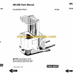
Model: RR30B Rider Truck
Type of Document: Full Manual (Service, Parts and Operators Manual)
$ 70
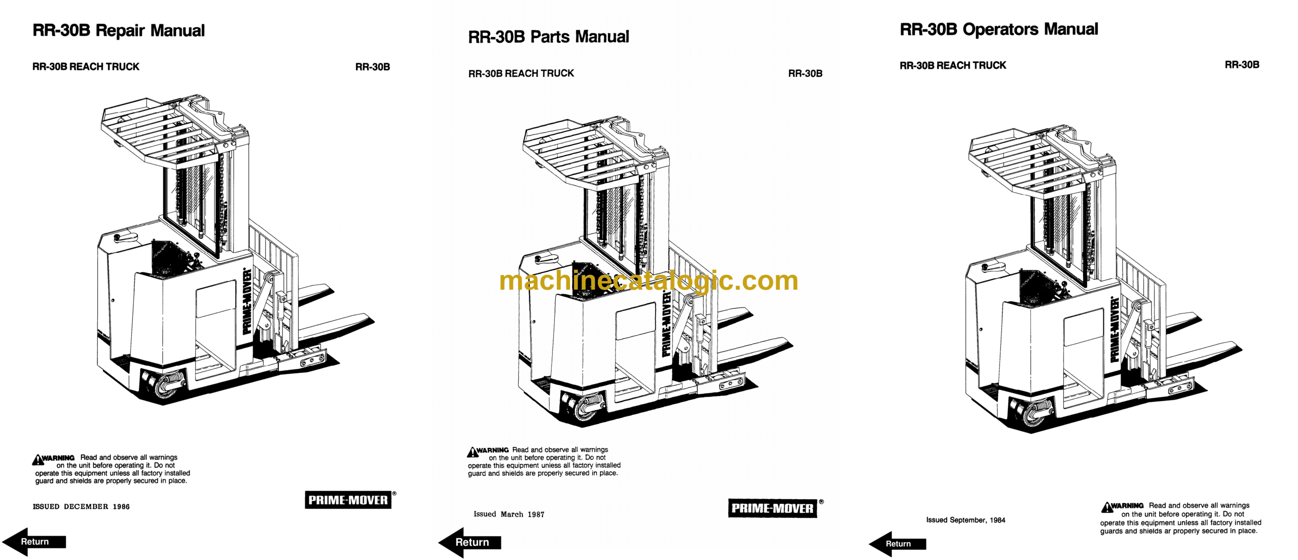
BT RR30B Rider Truck Full Manual (Service, Parts and Operators Manual)
Front Cover
Introduction
Important Notice
Preliminary Service
Index
Warning
Operating Rules and Instructions
Parts Ordering Instructions
Field Modifications
Dealers Owners Record
Frame Index
Instruments and Dash Controls Index
Transmission Index
Electrical System Index
Hydraulic Index
Tires Index
Shielding Index
Jacking and Hoisting Index
Mast System Index
Specification Tables and Charts Index
Troubleshooting Index
Back Cover
Front Cover
Warranty
Parts Ordering Instructions
General Information
Figure 1 Parts List and Service Reference Index
Figure 2 Decal and Part Assembly
Figure 3 Shielding Assembly
Figure 4 Emergency Disconnect Assembly
Figure 5 Auxiliary Control Assembly
Figure 6 Hand Lift and Speed Assembly
Figure 7 Master Control Switch Assembly
Figure 8 Steering Assembly
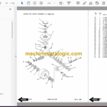
Figure 9 Torque Generator Assembly
Figure 10 Auxiliary Pump and Motor Assembly
Figure 11 Auxiliary Pump Assembly
Figure 12 Auxiliary Motor Assembly
Figure 13 Transmission and Drive Motor Insulation
Figure 14 Drive Motor and Brake Assembly
Figure 15 Drive Motor Assembly
Figure 16 Transmission Assembly
Figure 17 Electrical Schematic
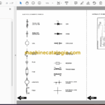
Figure 18 Electrical Schematic Symbols
Figure 21 Wiring Harness Assembly
Figure 22 Wiring Assembly for Cold Storage
Figure 23 2 Stage Mast Cable Assembly
Figure 24 3 Stage Mast Cable Assembly
Figure 25 Reach Cable Assembly
Figure 26 Power Component Wiring
Figure 27 SCR and Contactor Panel Assembly
Figure 28 EV-1 SCR Control
Figure 29 Transformer Assembly
Figure 30 Rectifier Heat Sink Assembly
Figure 31 GE Contactor Assembly
Figure 32 GE Contactor Assembly
Figure 33 Contactor Assembly
Figure 34 Connector Assembly
Figure 35 Warning Light Assembly
Figure 36 Hydraulic Schematic
Figure 37 Hydraulic Schematic Symbols
Figure 38 Auxiliary Pump and Reservoir Assembly
Figure 39 Hydraulic Reservoir Assembly
Figure 40 Lift Pump and Motor Assembly
Figure 41 Lift Pump and Motor Assembly
Figure 42 Lift Motor Assembly
Figure 43 24 Volt Lift Pump Assembly
Figure 44 36 Volt Lift Pump Assembly
Figure 45 Lift Control Valve Assembly
Figure 46 Torque Generator and Filter Assembly
Figure 47 Tube and Hose Assembly
Figure 48 Auxiliary Control Valve Assembly
Figure 49 2 Stage Cylinder and Reservoir Assembly
Figure 50 2 Stage Cylinder Assembly
Figure 51 3 Stage Cylinders and Reservoir Assembly
Figure 52 3 Stage Staging Cylinder Assembly
Figure 53 3 Stage Freelift Cylinder Assembly
Figure 54 2 Stage Mast Hydraulic Hose Assembly
Figure 55 3 Stage Mast Hydraulic Hose Assembly
Figure 56 Standard Reach Hose Assembly
Figure 57 Flow Divider Assembly
Figure 58 Reach and Tilt Cylinder Assembly
Figure 59 Reach with Tilt Hose Assembly
Figure 60 Reach with Tilt Manifold Valve Assembly
Figure 61 Sideshifter Hose Assembly
Figure 62 Sideshifter Cylinder Assembly
Figure 63 Sideshifter Manifold Valve Assembly
Figure 64 Deep Reach, Valve and Hose Assembly
Figure 65 Deep Reach, Reach Cylinder and Hose Assembly
Figure 66 Deep Reach, Manifold Valve Assembly
Figure 67 Deep Reach, Reach Cylinder Assembly
Figure 68 Deep Reach, Tilt Cylinder and Hose Assembly
Figure 69 Deep Reach, Tilt Cylinder Assembly
Figure 70 Deep Reach, Sideshifter Hose Assembly
Figure 71 2 Stage Mast Insulation Assembly
Figure 72 2 Stage Inner Column Assembly
Figure 73 2 Stage Outer Column Assembly
Figure 74 2 Stage Cylinder Assembly and Related Parts
Figure 75 Single Reach Assembly
Figure 76 Single Reach Standard Front Frame Assembly
Figure 77 Single Reach Tilt Front Frame Assembly
Figure 78 Deep Reach Assembly
Figure 79 Sideshifter Assembly
Figure 80 Fork Assembly
Figure 81 3 Stage Mast Insulation Assembly
Figure 82 3 Stage Outer Column Assembly
Figure 83 3 Stage Intermediate Column Assembly
Figure 84 3 Stage Inner Column Assembly
Figure 85 3 Stage Freelift Cylinder Assembly and Related Parts
Figure 86 Main Frame and Load Wheel Assembly
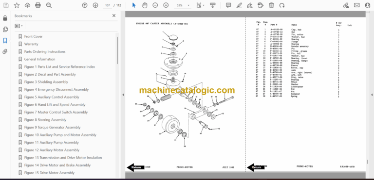
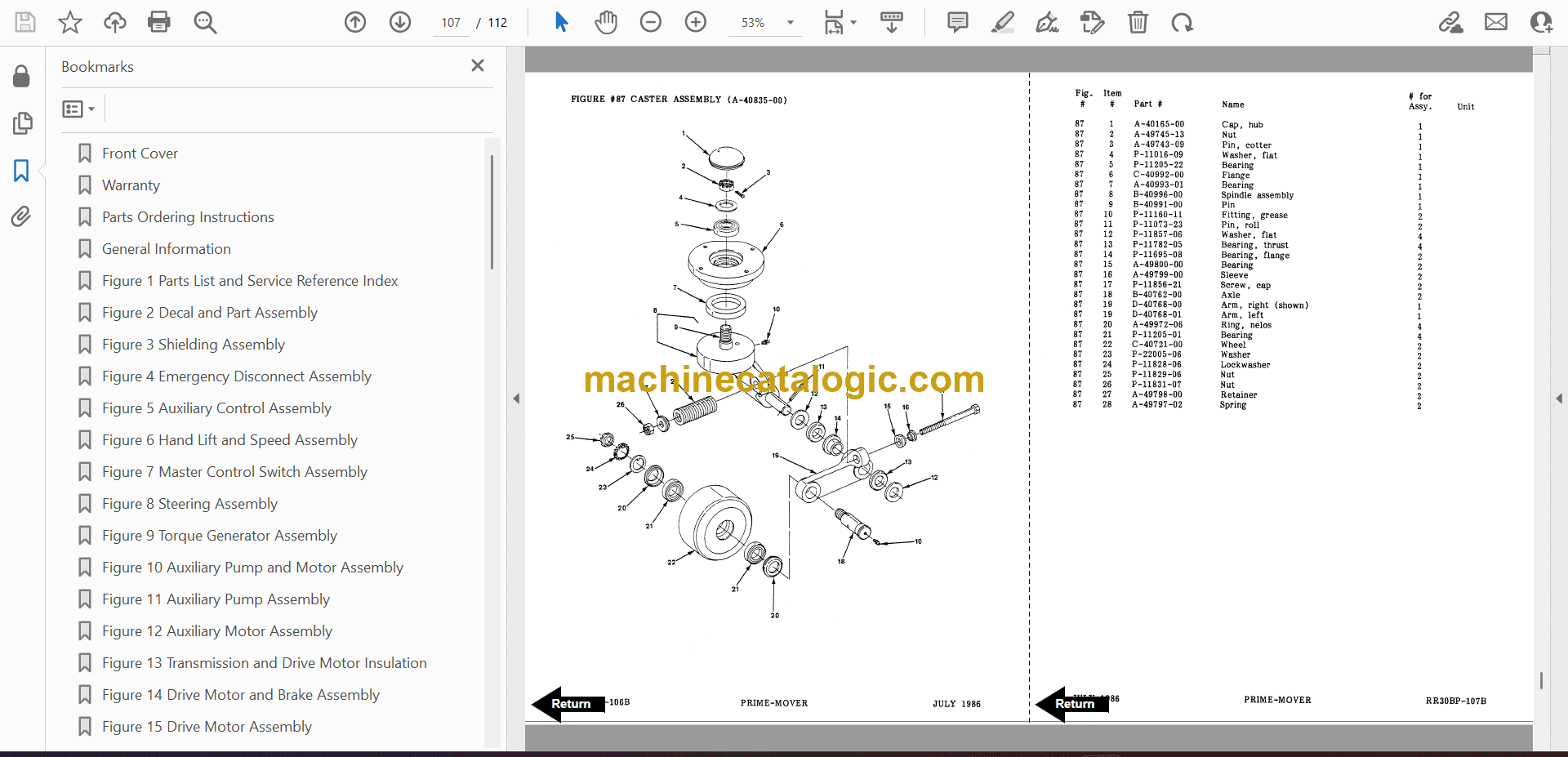
Figure 87 Caster Assembly
Figure 88 Single Load Wheel Assembly
Figure 89 4 Inch High Outriggers Articulating Load Wheel Assembly
Figure 90 Articulating Load Wheel Assembly
Back Cover
Front Cover
Warranty
To New Prime-Mover Owners
Contents
Preliminary Service
Operation
Operating Rules and Instructions
Data Plate and Decals
Controls and Safety Equipment
Periodic Maintenance Chart
Lubrication Chart
Before Operation
Operation
Parking
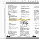
Maintenance Instructions
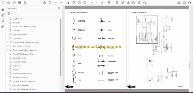
Electrical Schematic
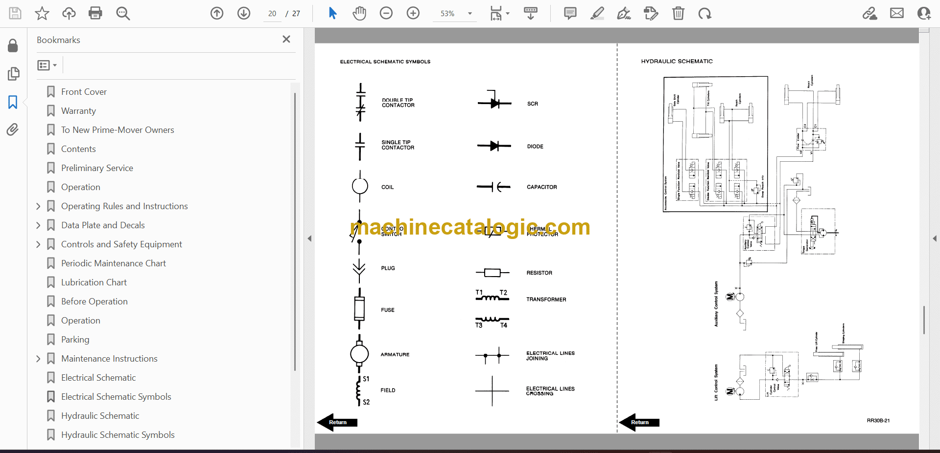
Electrical Schematic Symbols
Hydraulic Schematic
Hydraulic Schematic Symbols
Parts Ordering Instructions
RR30B Electric Reach Truck Specifications
Service Guide
Back Cover
