Format: PDF (Printable Document)
File Language: English
Brand: BT
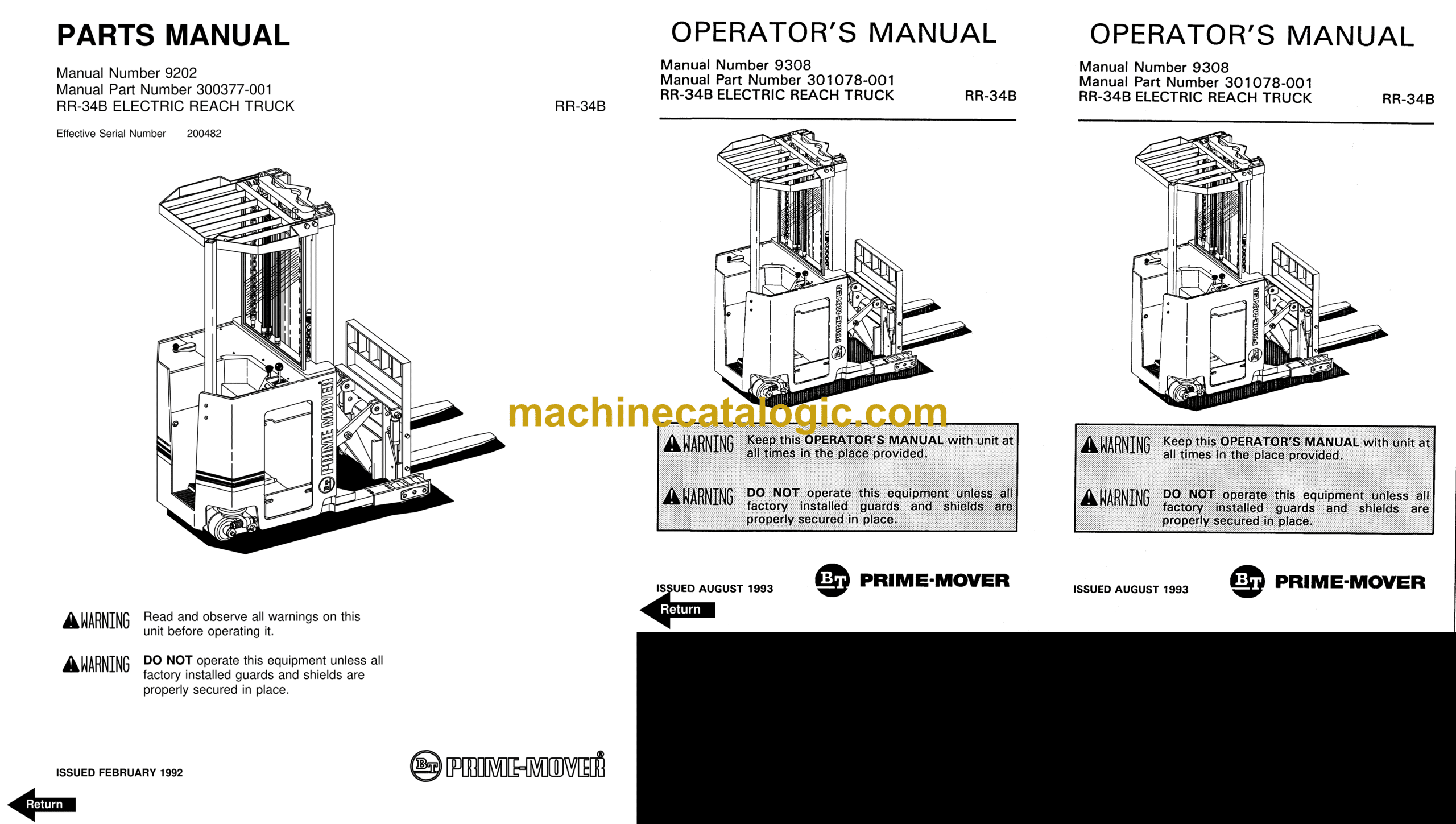
Model: RR34B Rider Truck
Type of Document: Operator and Parts Manual
$ 70
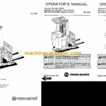
BT RR34B Rider Truck Operator and Parts Manual
Front Cover
Parts Ordering Instructions
General Information
Alphabetical Index
Figure # 0.1 Decals and Parts Assembly
Figure # 0.2 Parts List Index
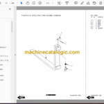
Figure # 1.1 Transmission and Drive Motor Installation
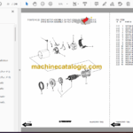
Figure # 1.2 Drive Motor and Brake Assembly
Figure # 1.3 Transmission Assembly (40011-01) Part # I)
Figure # 1.4 Transmission Assembly (40011-00) Part # II)
Figure # 2.1 “E” EV-100LX SCR Electrical Schematic
Figure # 2.2 “E” EV-100LX SCR Electrical Schematic Symbols
Figure # 2.3 “EE” EV-100LX SCR Electrical Schematic
Figure # 2.4 “EE” EV-100LX SCR Electrical Schematic Symbols
Figure # 2.5 Wiring Assembly for Cold Storage
Figure # 2.6 Wiring Harness Assembly
Figure # 2.7 Limit Switch Wiring Assembly
Figure # 2.8 Two Stage Mast Cable Assembly
Figure # 2.9 Three Stage Mast Cable Assembly
Figure # 2.10 Single Reach Cable Assembly
Figure # 2.11 Double Reach Cable Assembly
Figure # 2.12 EV-100LX Power Component Wiring
Figure # 2.13 EV-100LX TX SCR Control Panel Assembly (49399-00) & EV-100LX TT SCR Control Panel Assembly (49399-01)
Figure # 2.14 EV-100LX Contactor Panel Assembly & Related Parts for “E” and “EE”
Figure # 2.15 EV-100LX Contactor Panel Assembly (24 Volt, 41757-01) (36 Volt, 41757-02)
Figure # 2.16 EV-100LX SCR Forward & Rearward Contactor Assembly (27692-00)
Figure # 2.17 EV-100LX SCR 1A Contactor Assembly (27693-02)
Figure # 2.18 Lift Pump Contactor Assembly (24 Volt, 27693-02) (36 Volt, 202169)
Figure # 2.19 EV-100LX SCR Auxiliary Pump Contactor Assembly (300073-000)
Figure # 2.20 Power Connector Assembly (24 Volt, 49855-24) (36 Volt, 49855-22)
Figure # 2.21 Lift Pump Motor Assembly, 24 Volt (27900-00, 5BT1324B54) G.E. & Lift Pump Motor Assembly, 36 Volt (27899-00, 5B
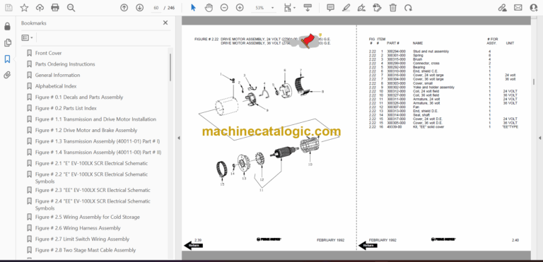
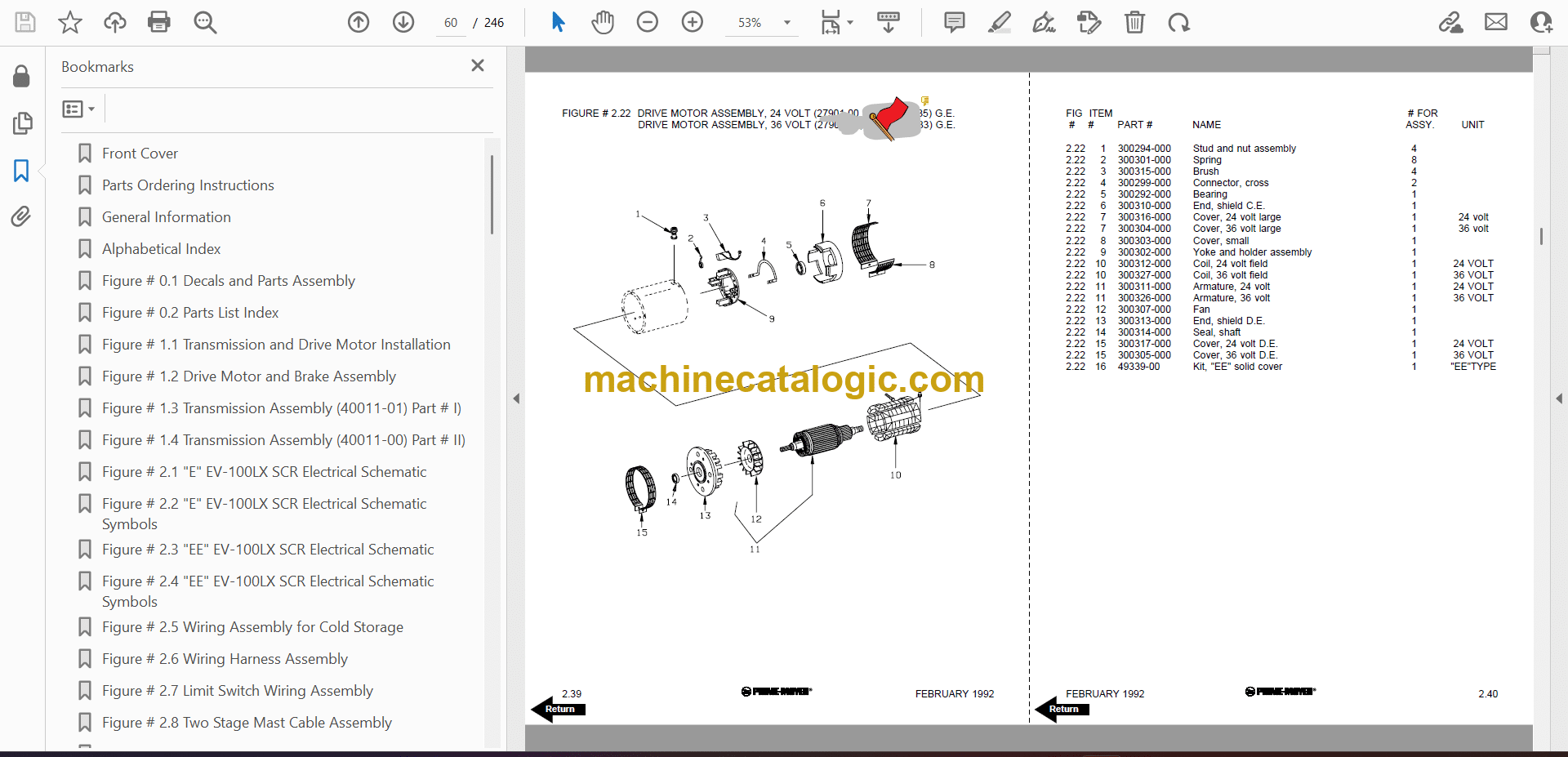
Figure # 2.22 Drive Motor Assembly, 24 Volt (27901-00, 5BT1326B235) G.E. & Drive Motor Assembly, 36 Volt (27902-00, 5BT1326B2
Figure # 2.23 Auxiliary Pump Motor Assembly
Figure # 2.24 Warning Light Assembly
Figure # 2.25 “E” EV-100LX TT SCR Electrical Schematic
Figure # 2.26 “E” EV-100LX TT SCR Electrical Schematic Symbols
Figure # 2.27 “EE” EV-100LX TT SCR Electrical Schematic
Figure # 2.28 “EE” EV-100LX TT SCR Electrical Schematic Symbols
Figure # 2.29 EV-100LX Dash Display Installation
Figure # 3.1 Hydraulic Schematic
Figure # 3.2 Hydraulic Schematic Symbols
Figure # 3.3 Auxiliary Pump and Reservoir Assembly
Figure # 3.4 Auxiliary Control Valve Assembly
Figure # 3.5 Auxiliary Pump and Motor Assembly
Figure # 3.6 Auxiliary Pump Assembly
Figure # 3.7 Hydraulic Reservoir Assembly
Figure # 3.8 Torque Generator Assembly
Figure # 3.9 Two Stage Mast Hydraulic Assembly
Figure # 3.10 Three Stage Mast Hydraulic Assembly
Figure # 3.11 Single Reach Reach Cylinder Hose Installation
Figure # 3.12 Single Reach Diverter Valve Assembly
Figure # 3.13 Single Reach Reach Cylinder Assembly
Figure # 3.14 Single Reach, Tilt and Sideshift Hose Installation
Figure # 3.15 Single Reach Tilt Cylinder Assembly
Figure # 3.16 Double Reach with Tilt and Sideshifter
Figure # 3.17 Double Reach Diverter Valve Assembly
Figure # 3.18 Double Reach Reach Cylinder Assembly
Figure # 3.19 Double Reach Tilt Cylinder Assembly
Figure # 3.20 Lift Pump and Reservoir Assembly
Figure # 3.21 Lift Pump Motor Assembly
Figure # 3.22 Lift Pump Motor Assembly, 24 Volt
Figure # 3.23 Lift Pump Motor Assembly, 36 Volt
Figure # 3.24 Lift Control Valve Assembly
Figure # 3.25 Two Stage Cylinder and Reservoir Assembly
Figure # 3.26 Two Stage Cylinder Assembly
Figure # 3.27 Three Stage Cylinder and Reservoir Assembly
Figure # 3.28 Three Stage Staging Cylinder Assembly
Figure # 3.29 Three Stage Freelift Cylinder Assembly
Figure # 4.1 Shielding Assembly
Figure # 4.2 Emergency Disconnect Assembly
Figure # 4.3 Auxiliary Control Assembly
Figure # 4.4 Hand Lift/Lower and Speed Control
Figure # 4.5 Forward Steering Control Assembly
Figure # 4.6 Rearward Steering Control Assembly
Figure # 4.7 Auxiliary Pump and Motor Installation
Figure # 4.8 Main Frame and Load Wheel Assembly
Figure # 4.9 Single Load Wheel Assembly
Figure # 4.10 5″ High Articulating Load Wheel Assembly
Figure # 4.11 4″ High Articulating Load Wheel Assembly
Figure # 4.12 Caster Assembly
Figure # 5.1 Two Stage Mast Installation
Figure # 5.2 Two Stage Inner Column Assembly
Figure # 5.3 Two Stage Outer Column Assembly
Figure # 5.4 Two Stage Cylinder Installation
Figure # 5.5 Two Stage Single Reach Assembly
Figure # 5.6 Two Stage Single Reach Front Frame Assembly
Figure # 5.7 Two Stage Double Reach Assembly
Figure # 5.8 Two Stage Double Reach Front Frame Assembly
Figure # 5.9 Two Stage Sideshifter Assembly
Figure # 5.10 Two Stage Fork Assembly
Figure # 5.11 Three Stage Mast Installation
Figure # 5.12 Three Stage Inner Column Assembly
Figure # 5.13 Three Stage Freelift Cylinder Installation
Figure # 5.14 Three Stage Intermediate Column Assembly
Figure # 5.15 Three Stage Outer Column Assembly
Figure # 5.16 Three Stage Single Reach Assembly
Figure # 5.17 Three Stage Single Reach Front Frame Assembly
Figure # 5.18 Three Stage Double Reach Assembly
Figure # 5.19 Three Stage Double Reach Front Frame Assembly
Figure # 5.20 Three Stage Sideshifter Assembly
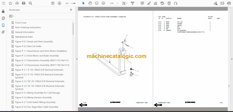
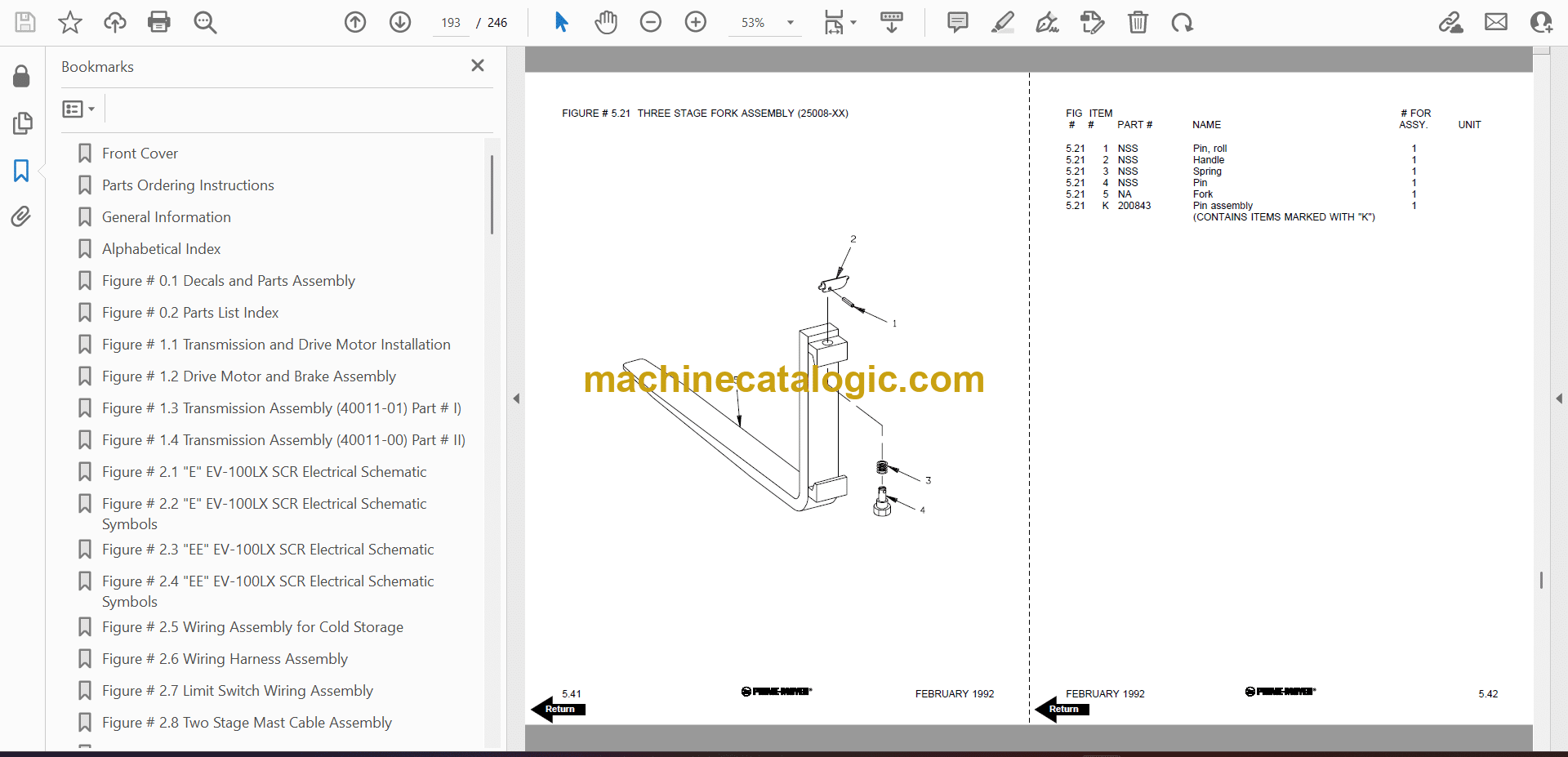
Figure # 5.21 Three Stage Fork Assembly
Figure # 6.1 Manlift EV-100 LX SCR Electrrical Schematic
Figure # 6.2 Manlift EV-100 LX SCR Electrical Schematic Symbols
Figure # 6.3 Three Stage Fork Assembly
Figure # 6.4 Manlift Three Stage Mast Cable Assembly
Figure # 6.5 Manlift Reach and Platform Cable Assembly
Figure # 6.6 Manlift Power Component Wiring
Figure # 6.7 Manlift Connector Assembly
Figure # 6.8 Manlift Hydraulic Schematic
Figure # 6.9 Manlift Hydraulic Schematic Symbols
Figure # 6.10 Manlift Hydraulic Diagram
Figure # 6.11 Block Manlift Valve Assembly
Figure # 6.12 Manlift Valve Assembly
Figure # 6.13 Manlift Load Backrest Installation
Figure # 7.1 Battery Lift Interrupt “E” EV-100LX SCR Electrical Schematic
Figure # 7.2 Battery Lift Interrupt “E” EV-100LX SCR Electrical Schematic Symbols
Figure # 7.3 Battery Lift Interrupt “EE” EV-100LX SCR Electrical Schematic
Figure # 7.4 Battery Lift Interrupt “EE” EV-100LX SCR Electrical Schematic Symbols
Figure # 7.5 Battery Lift Interrupt Installation
Figure # 10.1 Special Tools and Lubrications
Numerical Index
Back Cover
Front Cover
Important Notice
Foreword
Table of Contents
Drive Safely
Introduction
Preliminary Service
Operator
Operating Practices
Data Plate and Decals
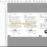
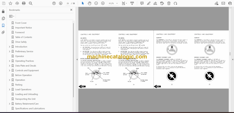
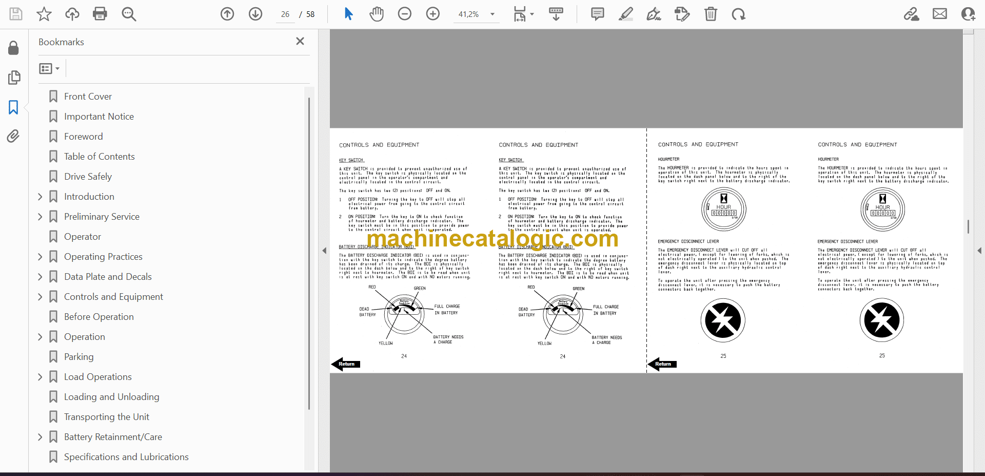
Controls and Equipment
Before Operation
Operation
Parking
Load Operations
Loading and Unloading
Transporting the Unit
Battery Retainment/Care
Specifications and Lubrications
Service Intervals
Field Modifications
Back Cover
