Format: PDF (Printable Document)
File Language: English
Brand: BT
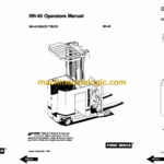
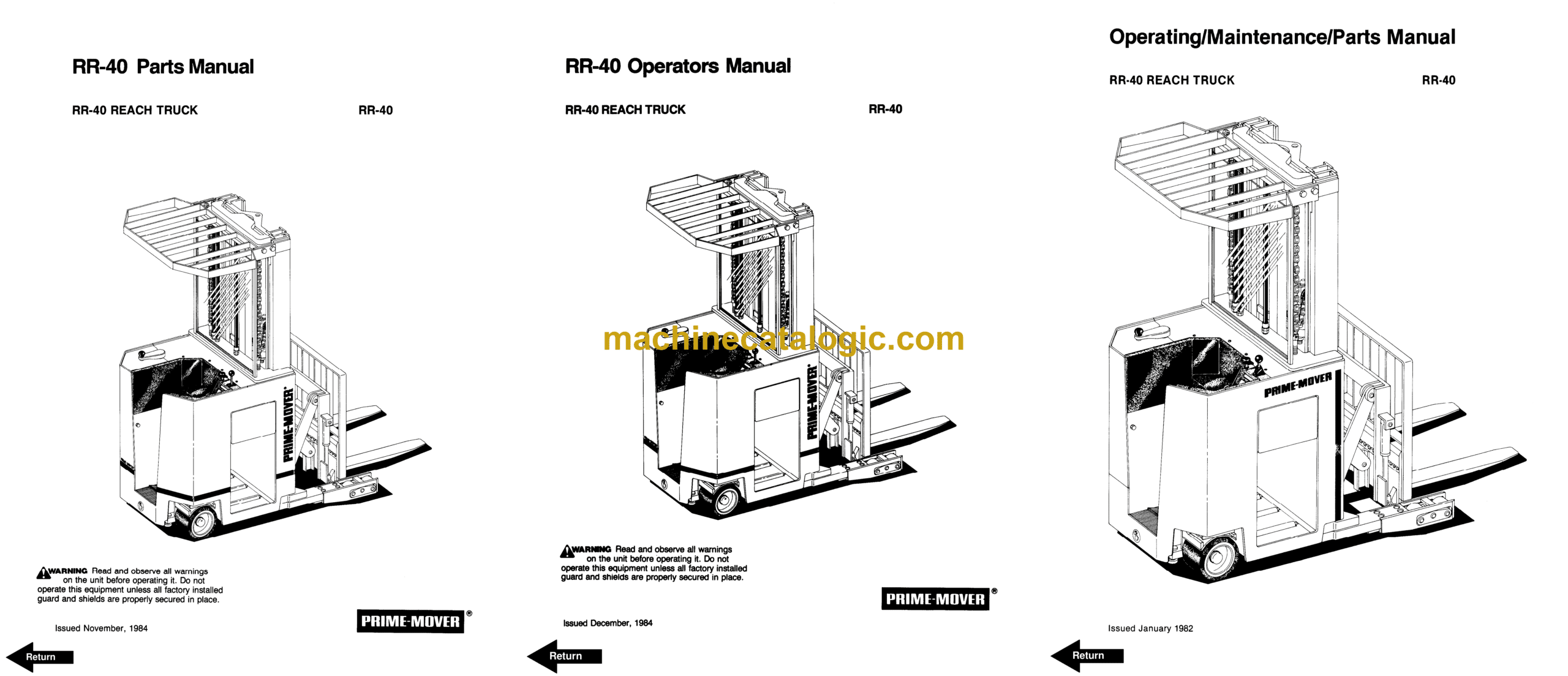
Model: RR40 Rider Truck
Type of Document: Maintenance, Operator and Parts Manual
$ 70
BT RR40 Rider Truck Maintenance, Operator and Parts Manual
Front Cover
Warranty
Parts Ordering Instructions
General Information
Figure # 1
Figure # 2
Figure # 3
Figure # 4
Figure # 5
Figure # 6
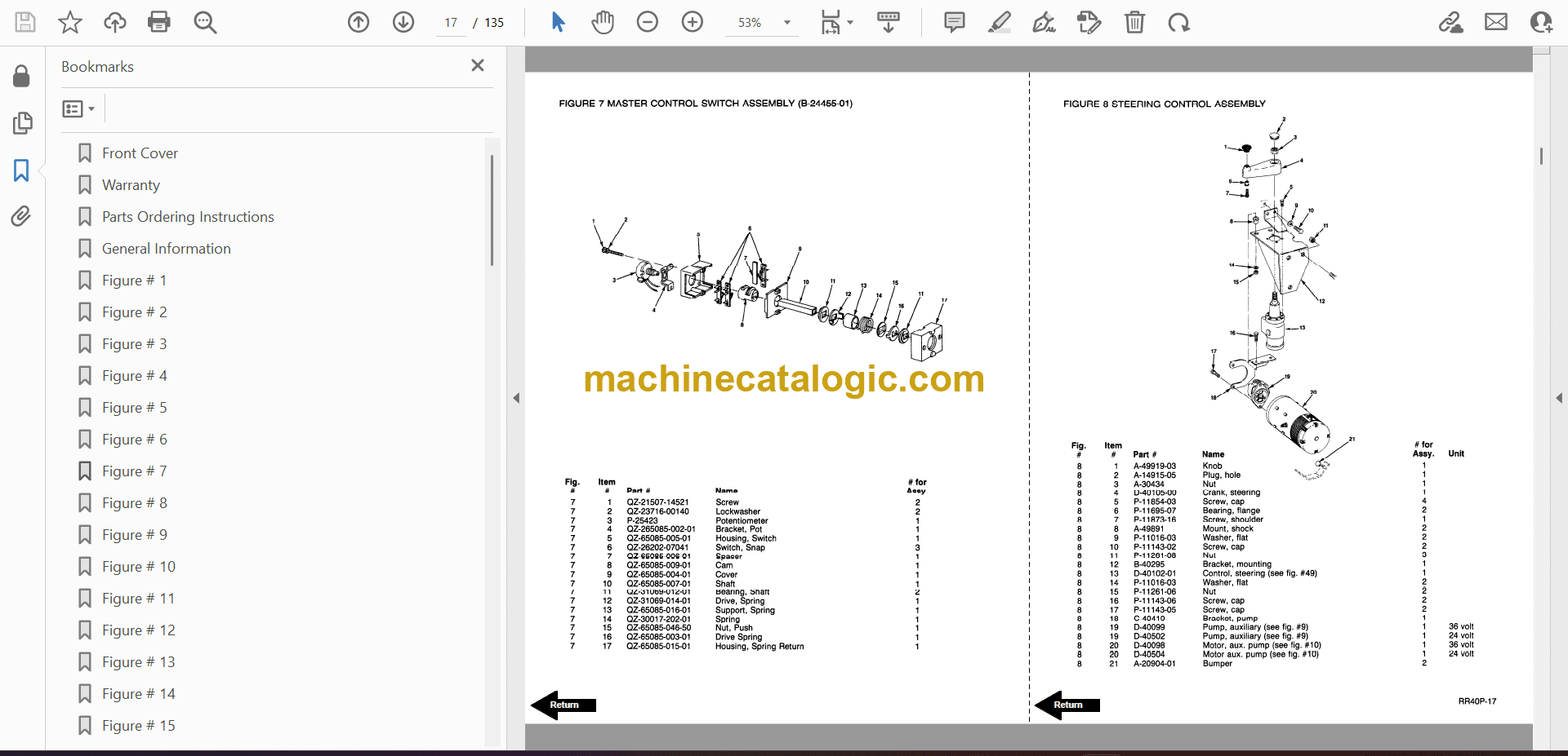
Figure # 7
Figure # 8
Figure # 9
Figure # 10
Figure # 11
Figure # 12
Figure # 13
Figure # 14
Figure # 15
Figure # 16
Figure # 17
Figure # 18
Figure # 19
Figure # 20
Figure # 21
Figure # 22
Figure # 23
Figure # 24
Figure # 25
Figure # 26
Figure # 27
Figure # 28
Figure # 29
Figure # 30
Figure # 31
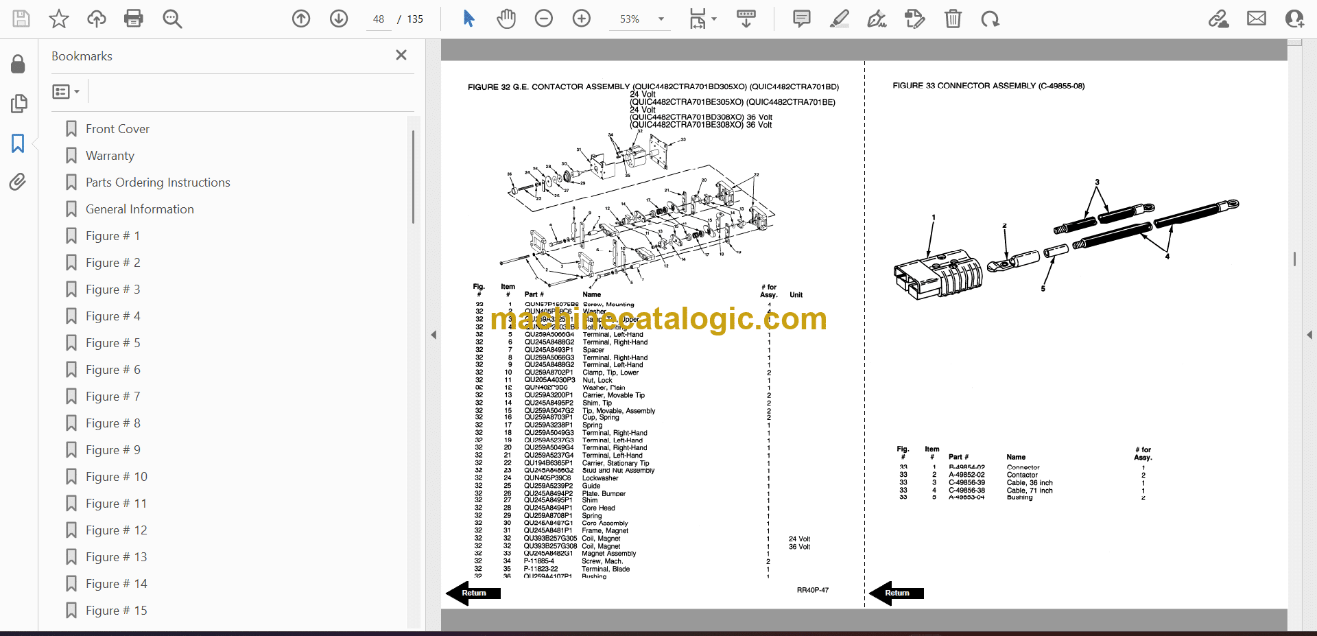
Figure # 32
Figure # 33
Figure # 34
Figure # 35
Figure # 36
Figure # 37
Figure # 38
Figure # 39
Figure # 40
Figure # 41
Figure # 42
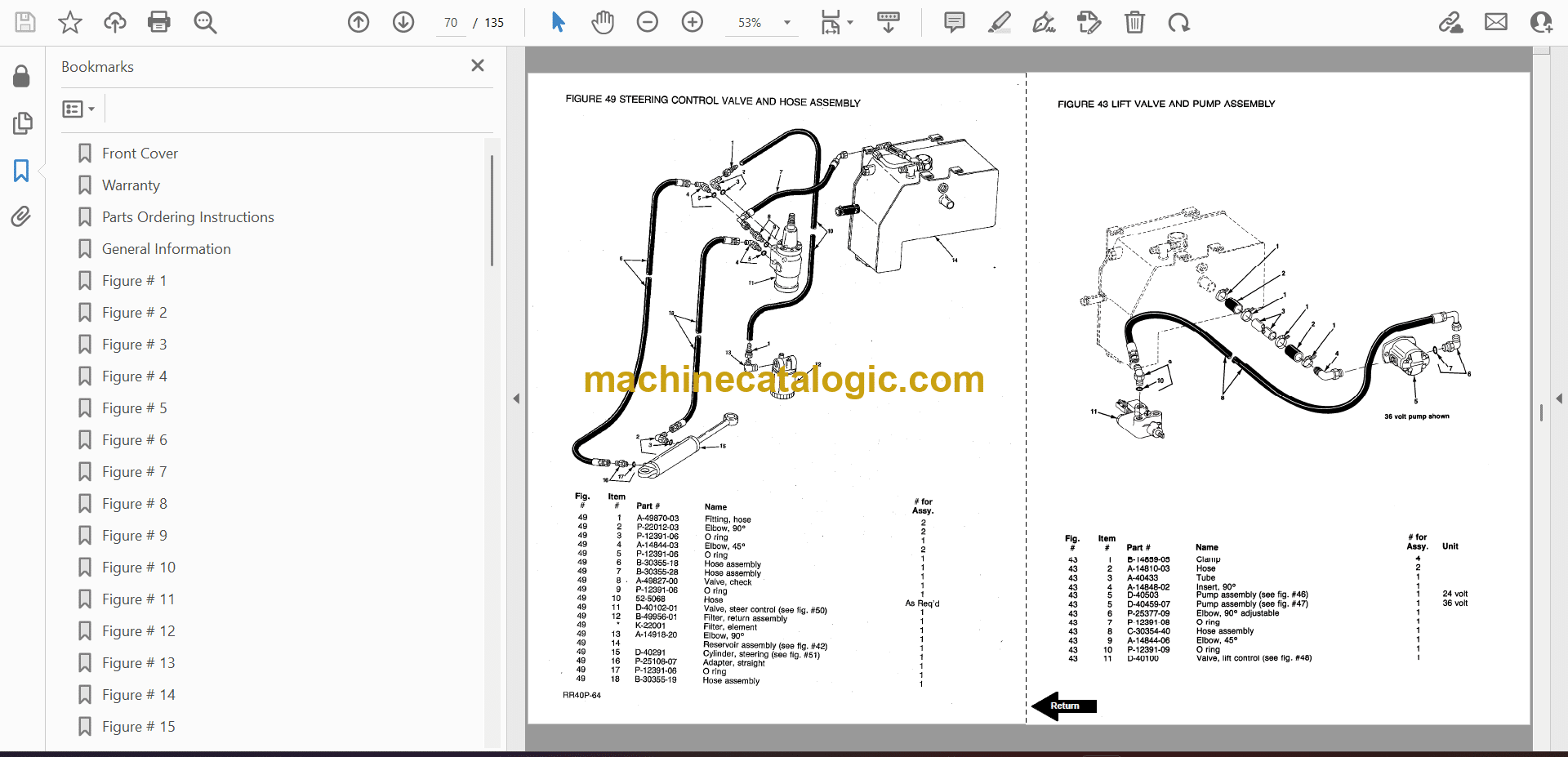
Figure # 43
Figure # 44
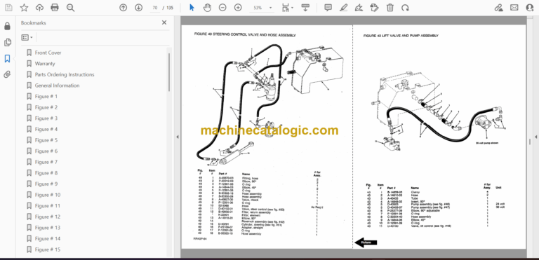
Figure # 45
Figure # 46
Figure # 47
Figure # 48
Figure # 49
Figure # 50
Figure # 51
Figure # 52
Figure # 53
Figure # 54
Figure # 55
Figure # 56
Figure # 57
Figure # 58
Figure # 59
Figure # 60
Figure # 61
Figure # 62
Figure # 63
Figure # 64
Figure # 65
Figure # 66
Figure # 67
Figure # 68
Figure # 69
Figure # 70
Figure # 71
Figure # 72
Figure # 73
Figure # 74
Figure # 75
Figure # 76
Figure # 77
Figure # 78
Figure # 79
Figure # 80
Figure # 81
Figure # 82
Figure # 83
Figure # 84
Figure # 85
Figure # 86
Figure # 87
Figure # 88
Figure # 89
Figure # 90
Figure # 91
Figure # 92
Back Cover
Front Cover
Warranty
To New Prime-Mover Owners
Contents
Preliminary Service
Operation
Operating Rules and Instructions
Data Plate and Decals
Controls and Safety Equipment
Lubrication Chart
Periodic Maintenance Chart
Deadman Brake
Brake Pedal Switch Adjustment
Motor Commutator
Hydraulic System
Auxiliary Pump
Power Steering and Brake
Lift System Pump Motor
Lift System
Auxiliary Control Valve Functions
Lift Cylinders
Before Operation
Operation
Parking
Maintenance Instructions
Parts Ordering Instructions
Electrical Schematic
Electrical Schematic Symbols
Hydraulic Schematic
Hydraulic Schematic Symbols
RR40 Electric Reach Truck Specifications
RR40 Electric Deep Reach Truck Specifications
Service Guide
Back Cover
Front Cover
Warranty
New Owners
Contents
Preliminary Service
Operation
Operating Rules and Instructions
Lubrication Chart
Maintenance Instructions
Service and Disassembly Instructions
Parts Ordering Instructions
Truck Specifications
Figure # 1 Decal and Part Assembly
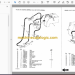
Figure # 2 Parts List and Service Reference Index
Figure # 3 Shield Assembly
Figure # 4 Emergency Disconnect and Auxiliary Control Assembly
Figure # 5 Hand Lift and Speed Assembly
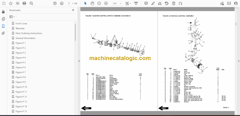
Figure # 6 Master Control Switch Assembly
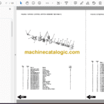
Figure # 7 Steering Control and Pump Assembly
Figure # 8 Auxiliary Pump Assembly
Figure # 9 Auxiliary Motor Assembly
Figure # 10 Transmission and Steering Insulation Assembly
Figure # 11 Brake Assembly
Figure # 12 Drive Motor Assembly
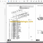
Figure # 13 Transmission Assembly
Figure # 14 Idler Wheel Insulation Assembly
Figure # 15 Electrical Schematic
Figure # 16 Electrical Schematic Symbols
Figure # 17 Wiring Harness Assembly
Figure # 18 Mast Cable Assembly
Figure # 19 Reach Cable Assembly
Figure # 20 Power Component Wiring
Figure # 21 SCR and Contactor Panel Assembly
Figure # 22 EV-1 SCR Control
Figure # 23 Transformer Assembly
Figure # 24 Rectifier Heat Sink Assembly
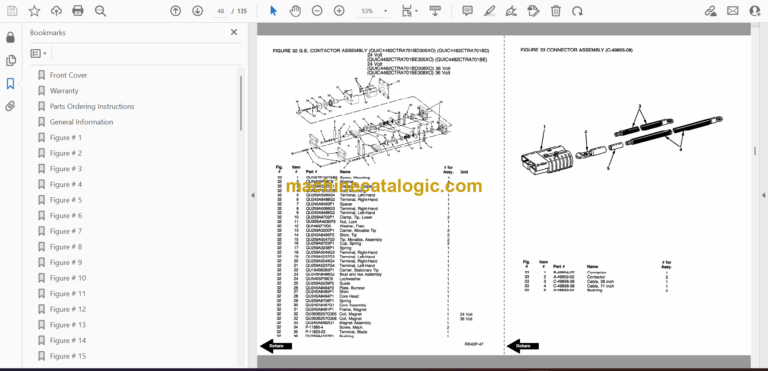
Figure # 25 GE Contactor Assembly
Figure # 26 Power Steering Contactor Assembly
Figure # 27 GE Contactor Assembly
Figure # 28 Hydraulic Schematic
Figure # 29 Hydraulic Schematic Symbols
Figure # 30 Hydraulic Assembly Part # 1
Figure # 31 Brake Solenoid Valve
Figure # 32 Brake Cylinder Assembly
Figure # 33 Hydraulic Reservoir Assembly
Figure # 34 Hydraulic Assembly Part # 2
Figure # 35 Lift Pump and Motor Assembly
Figure # 36 Lift Motor Assembly
Figure # 37 Lift Pump Assembly
Figure # 38 Lift Control Valve Assembly
Figure # 39 Hydraulic Assembly Part # 3
Figure # 40 Steer Control Valve
Figure # 41 Steer Cylinder Assembly
Figure # 42 Auxiliary Control Valve Assembly
Figure # 43 Hydraulic Assembly Part # 4
Figure # 44 Freelift Cylinder Assembly
Figure # 45 Staging Cylinder Assembly
Figure # 46 Mast Hydraulic Hose Assembly
Figure # 47 Standard Reach Hose Assembly
Figure # 48 Reach and Tilt Cylinder Assembly
Figure # 49 Reach with Tilt Hose Assembly
Figure # 50 Reach with Tilt Manifold Valve Assembly
Figure # 51 Sideshifter Hose Assembly
Figure # 52 Sideshifter Cylinder Assembly
Figure # 53 Sideshifter Manifold Valve
Figure # 54 3 Stage Mast Insulation Assembly
Figure # 55 Outer Column Assembly
Figure # 56 Intermediate Column Assembly
Figure # 57 Inner Column Assembly
Figure # 58 3 Stage Freelift Cylinder Assembly
Figure # 59 Reach Assembly
Figure # 60 Standard Reach Front Frame Assembly
Figure # 61 Tilt Reach Front Frame Assembly
Figure # 62 Fork Assembly
Figure # 63 Sideshifter Assembly
Figure # 64 Main Frame and Load Wheel Assembly
Service Guide
Back Cover
