Format: PDF (Printable Document)
File Language: English
File Pages: 614
File Size: 23.88 MB (Speed Download Link)
Brand: BT
Model: RRX35, RRX45, RDX30, RSX40, RSX50
Part No: 306756-000
Type of Document: Master Service Manual
$ 40
Standard Codes
Warning Symbols
1. Warning Levels
Prohibitory Symbols
1. Ordinance Symbols
Safety
1. General Safety
Battery Safety
Static Safety
Welding Safety
Introduction, Service Manual
Contents, Section M
1. Machine Information
General Product Information
1. Presentation of the Rider Trucks.
2. Main Components
Inch (SAE) and Metric Fasteners
1. Introduction
2. Nomenclature, Threads
3. Strength Identification
4. Conversion of Metric and English Units
Technical Service Data
Ordering Spare Parts
Contents, Section P
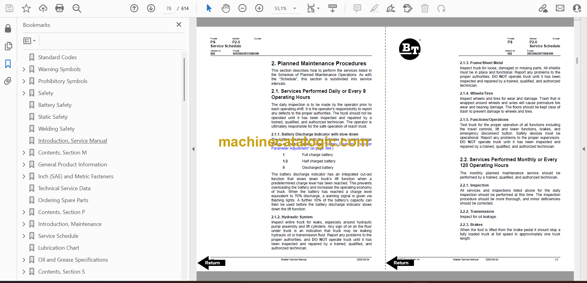
1. Planned Maintenance
Introduction, Maintenance
1. Jacking Truck Off The Floor
2. Lubricants
Service Schedule
1. Planned Maintenance Schedule
2. Planned Maintenance Procedures
Lubrication Chart
Oil and Grease Specifications
1. Approved Oils and Grease
2. Grease Location Points
3. Mast Adjustment Points
Contents, Section S
1. Service Instructions
Troubleshooting Guidelines
1. General
2. Electrical
3. Hydraulic
4. Definitions
Chassis
1. General
2. Dash
3. Motor Compartment Door
4. Left-Hand Side Panel
5. Operator Compartment Panel
6. Main Card Access Panel
Battery Compartment
1. Battery Retainer Plates
2. Battery Rollers
Driver Controls
Brake Pedal, RSX40/RRX35
1. Pedal Removal
2. Pedal Bearing Replacement
3. Pedal Adjustment
Brake Pedal, RSX50/RRX45/ RDX30
1. Pedal Removal
2. Pedal Bearing Replacement
3. Pedal Adjustment
Overhead Guard
Decals
1. Decal with Protective Sheet
2. Decal without Protective Sheet
Steering Motor
1. Removal
2. Installation
3. Steering Motor Gear Replacement
Fan Motor
1. Upper Electrical Compartment Fan
2. Operator Fan
Motor Maintenance Schedule/Troubleshooting
1. General Information
2. Operating Conditions
3. Troubleshooting
Motor Repair
1. Disassembly
2. Motor Inspection
Pump Motor
1. Mounting Points
2. Repair
Drive Motor
1. Mounting Points
2. Repair
Transmission
1. Mounting Points
2. Repair
3. Disassemble
4. Assembly
5. Axle Sealing Ring
6. Leakage
7. Wheel Bolt
Electromagnetic Brake
1. Removal
2. Installation
3. Adjustments
4. Coil Check On Brake
5. Electromagnetic Brake, Armature and Magnetic Coil
6. Brake Friction Plate
Drive Wheel
1. Removal
2. Installation
3. Tire Pressing Procedure
Non-Braking Caster Wheel, RRX35/ RSX40
1. Caster Pivot
2. Thrust Bearing
3. Caster Springs
4. Caster Stops
Non-Braking Caster Assembly, RRX35/RSX40
1. Removal
2. Installation
Braking Caster Wheel, RRX45/RDX30/ RSX50
1. Removal
Braking Caster Assembly, RRX45/ RDX30/RSX50
1. Removal
2. Installation
Load Wheels, Sizes 4 X 3, 5 X 4, and 5 X 3
1. Removal
2. Installation
Load Wheels, Size 10.5 X 3.5
1. Removal
2. Installation
Steering Arm / Wheel / Lever
1. Control Pod
2. Steering Wheel
3. Steering Tach
Steering Bearing
1. Removal
2. Installation
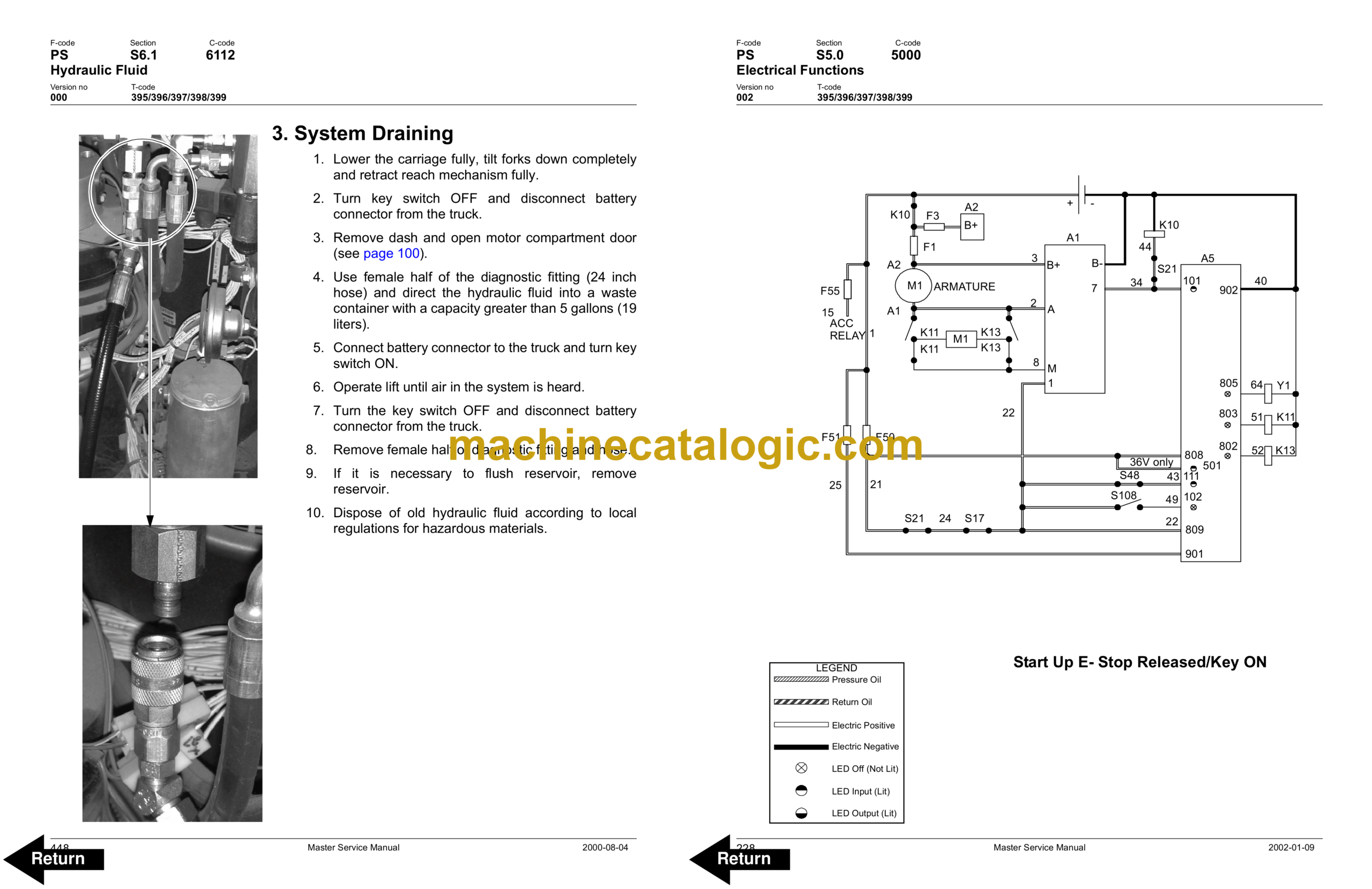
Electrical Functions
1. General
2. Start Up
3. Steering Components
4. Brake Release
5. Direction Selection
6. Travel Request, Forks First
7. Travel Request, Forks Trailing
8. Plug Braking
9. 12-Volt Power Supply
10. 7.35-Volt Power Supplies
11. Limit Switches
12. Height Indicator
13. Drive Motor Brush Wear Indicator Switches
14. Pump Motor Brush Indicator Switch
15. Safety Check
16. Shunt Power Cable
Electrical Symbols
Electrical Schematics (Serial numbers 27163000-28105000)
1. Circuit Diagram 1(11)
2. Circuit Diagram 2(11)
3. Circuit Diagram 3(11)
4. Circuit Diagram 4(11)
5. Circuit Diagram 5(11)
6. Circuit Diagram 6(11)
7. Circuit Diagram 7(11)
8. Circuit Diagram 8(11)
9. Circuit Diagram 9(11)
10. Circuit Diagram 10(11)
11. Circuit Diagram 11(11)
Electrical Schematics (Serial numbers 28105001-28126000)
1. Circuit Diagram 1(12)
2. Circuit Diagram 2(12)
3. Circuit Diagram 3(12)
4. Circuit Diagram 4(12)
5. Circuit Diagram 5(12)
6. Circuit Diagram 6(12)
7. Circuit Diagram 7(12)
8. Circuit Diagram 8(12)
9. Circuit Diagram 9(12)
10. Circuit Diagram 10(12)
11. Circuit Diagram 11(12)
12. Circuit Diagram 12(12)
Electrical Schematics (Serial numbers 28126001-31285000)
1. Circuit Diagram 1(12)
2. Circuit Diagram 2(12)
3. Circuit Diagram 3(12)
4. Circuit Diagram 4(12)
5. Circuit Diagram 5(12)
6. Circuit Diagram 6(12)
7. Circuit Diagram 7(12)
8. Circuit Diagram 8(12)
9. Circuit Diagram 9(12)
10. Circuit Diagram 10(12)
11. Circuit Diagram 11(12)
12. Circuit Diagram 12(12)
Electrical Schematics (Serial numbers 31285001-UP)
1. Circuit Diagram 1(12)
2. Circuit Diagram 2(12)
3. Circuit Diagram 3(12)
4. Circuit Diagram 4(12)
5. Circuit Diagram 5(12)
6. Circuit Diagram 6(12)
7. Circuit Diagram 7(12)
8. Circuit Diagram 8(12)
9. Circuit Diagram 9(12)
10. Circuit Diagram 10(12)
11. Circuit Diagram 11(12)
12. Circuit Diagram 12(12)
Battery
1. Removal
2. Installation
3. Battery Maintenance
4. Storage
5. Battery History Record
Light Assemblies
1. Overhead Guard Lights (Option)
2. Warning Lights (Option)
3. Working Lights (Option)
4. Travel Alarm (Option)
5. Operator Fan (Option)
Horn
1. Removal
2. Installation
Start/Stop Switches
1. General
2. Key Switch (S17)
3. Emergency Disconnect Switch (S21)
Battery Connector
1. Location
2. Inspection
3. Installation
Mast Switch (S31)
1. General
Control Cable and Harness
1. Fuses
2. Wiring
Contactors
1. General
2. Direction Contactors
3. Lift Bypass Contactor (RRX45/RSX50/RDX30)
4. Main Contactor
Transistor Panel (Drive)
1. Motor Connections
Transistor Panel (Lift)
2. Circuit Check, Drive Only
Micro Switches
1. General
2. Lift Limit Override Switch (S33) Optional
3. Optional Light and Fan Switches (S96, S97 and S99)
Main Electronic Card
1. Connectivity to Truck
2. Transistor Controller Replacement
3. Removal
4. Installation
5. Display
6. Time
7. Effect on Truck
8. Running time
9. RV2 Adjustment Procedure
10. Adjustment Procedures for Setting Brake Switch and Brake Transducer
11. Battery Discharge Indicator Parameter Adjustment
12. A5 Jumper Harness Kit Installation (Serial numbers 28126000 – below)
13. Warning\Caution Codes
14. Error Codes
15. Programming Parameter
Switches and Sensors
1. General
2. Platform (Right Foot) Switch (S108)
3. Staging Switch (S45)
4. Wheel Direction Sensor
5. Steer Proximity Sensors A and B (S66 and S67)
6. Drive Motor Speed(S64)/Direction Sensors (S125)
Hydraulic System
1. Operation
2. RRX35 Hydraulic Schematic
3. RRX45 Hydraulic Schematic
4. RDX30 Hydraulic Schematic
5. RSX40 Hydraulic Schematic
6. RSX50 Hydraulic Schematic
Hydraulic Fluid
1. Hydraulic Fluid Selection
2. Changing Hydraulic System Fluid
3. System Draining
4. Refilling System
5. Bleeding Hydraulic System
Hydraulic Tank
1. Removal
2. Installation
Hydraulic Filter Assembly
1. Hydraulic Filter
2. Hydraulic Filter Adapter
Hydraulic Pump
1. Removal
2. Repair
Control Valve
1. Removal
2. Installation
Control Valve Assembly
3. Repair
Staging Cylinder, Three Stage Mast
1. Bearing Removal
2. Disassembly
3. Assembly
4. Installation
Freelift Cylinder, Three Stage Mast
1. Removal
2. Disassembly
3. Assembly
4. Installation
Reach Cylinder Assembly
1. Removal
2. Disassembly
3. Inspection
4. Assembly
5. Installation
Tilt Cylinder Assembly, RRX35/RSX40/ RSX50
1. Removal
2. Disassembly
3. Inspection
4. Assembly
5. Installation
Tilt Cylinder Assembly, RRX45/RDX30
1. Removal
2. Disassembly
3. Inspection
4. Assembly
5. Installation
Mast, 3 Stage
1. Shimming Carriage with Mast on Truck
2. Three Stage Mast
3. Lift Chain
Lifting Gear (Crosshead)
1. Lifting Gear Repair
Sideshifter, RRX35/45/RDX30
1. Mounting Instructions
2. Operation and Maintenance
Sideshifter, RRX35/45/RSX40/50/RDX30
1. Mounting Instructions
2. Operation
3. Maintenance
4. Troubleshooting
Single Reach, RRX35
1. Maintenance
2. Reach Repair
3. Carriage Bumpers
4. Fork Carriage Pivot Pins
5. Carriage Roller Bearings
Single Reach, RRX45
1. Maintenance
2. Reach Repair
3. Fork Carriage Pivot Pins
4. Carriage Roller Bearings
Double Reach Mechanism, RDX30
1
Rod
24
Bearing
46
Bearing, 3 stage
2
Arm
25
Ring, Nilos
47
Cap, bearing
3
Bearing, thrust
26
Set, bearing
48
Screw
4
Bearing
27
Spacer
49
Bearing
5
Arm
28
Tilt cylinder assembly
50
Cap
6
Pin, roll
29
Screw
51
Screw
7
Pin
30
Pin
52
Block, bumper
8
Frame, fork
31
Screw, set
53
Bumper
9
Screw
32
Arm
54
Screw, socket head
10
Frame, forward
33
Nut, lock
55
Screw, socket head
11
Bearing
34
Arm
56
Lockwasher
12
Shim
35
Arm
57
Bushing
13
Arm
36
Pin
58
Bracket
14
Nut
37
Screw
59
Shield
15
Pin, cotter
38
Reach cylinder assembly
60
Screw, cap
16
Nut, slotted
39
Fitting, grease
61
Manifold
17
Washer
40
Frame, rear
62
Control valve
18
Ring, Nilos
41
Washer, shim
63
Cover
19
Cone, bearing
42
Screw
64
Screw, cap
20
Race, bearing
43
Bar, wear
65
Nut, flanged
21
Ring, retainer
44
Shim
66
Washer
22
Shim
45
Shim
67
Shim
23
Arm
1. Theory of Operation
2. Maintenance
3. Troubleshooting
4. Repair
5. Rebuild
Forks
1. Removal
2. Inspection
3. Installation
Load Indicator
Load Indicator
1. Pulse Sensor
Height Indicator and Preset Selector
1. General
2. Operation
3. Preset Height
4. Display
5. Display Symbols Description
6. Programming
Load Backrest
1. Removal
2. Installation


