Format: PDF (Printable Document)
File Language: English
Brand: BT
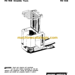
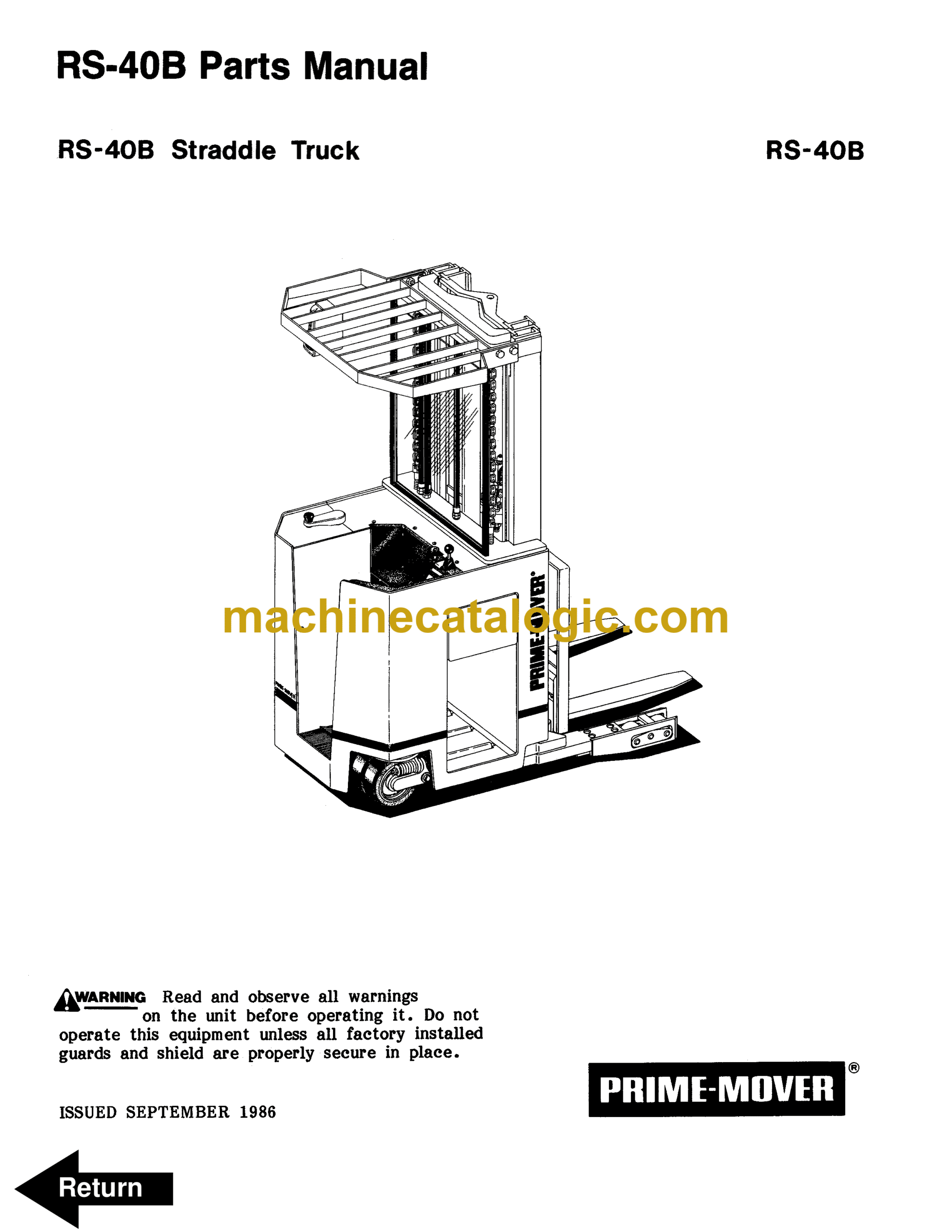
Model: RS40B Reach Truck
Type of Document: Operator and Parts Manual
$ 70
BT RS40B Reach Truck Operator and Parts Manual
Front Cover
Warranty
Parts Ordering Instructions
Field Modifications
General Information
Alphabetical Index
Figure # 1 Decal and Part Assembly
Figure # 2 Parts List and Service Reference Index
Figure # 3 Shielding Assembly
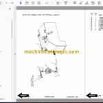
Figure # 4 Emergency Disconnect Assembly
Figure # 5 Auxiliary Control Assembly
Figure # 6 Hand Lift and Speed Assembly
Figure # 7 Master Control Switch Assembly
Figure # 8 Steering Control Assembly
Figure # 9 Torque Generator Assembly
Figure # 10 Auxiliary Pump and Motor Assembly
Figure # 11 Auxiliary Pump Assembly
Figure # 12 Auxiliary Motor Assembly
Figure # 13 Transmission and Drive Motor Insulation
Figure # 14 Drive Motor and Brake Assembly
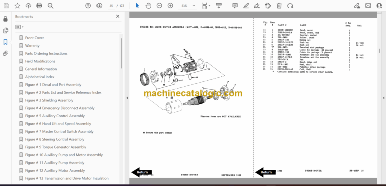
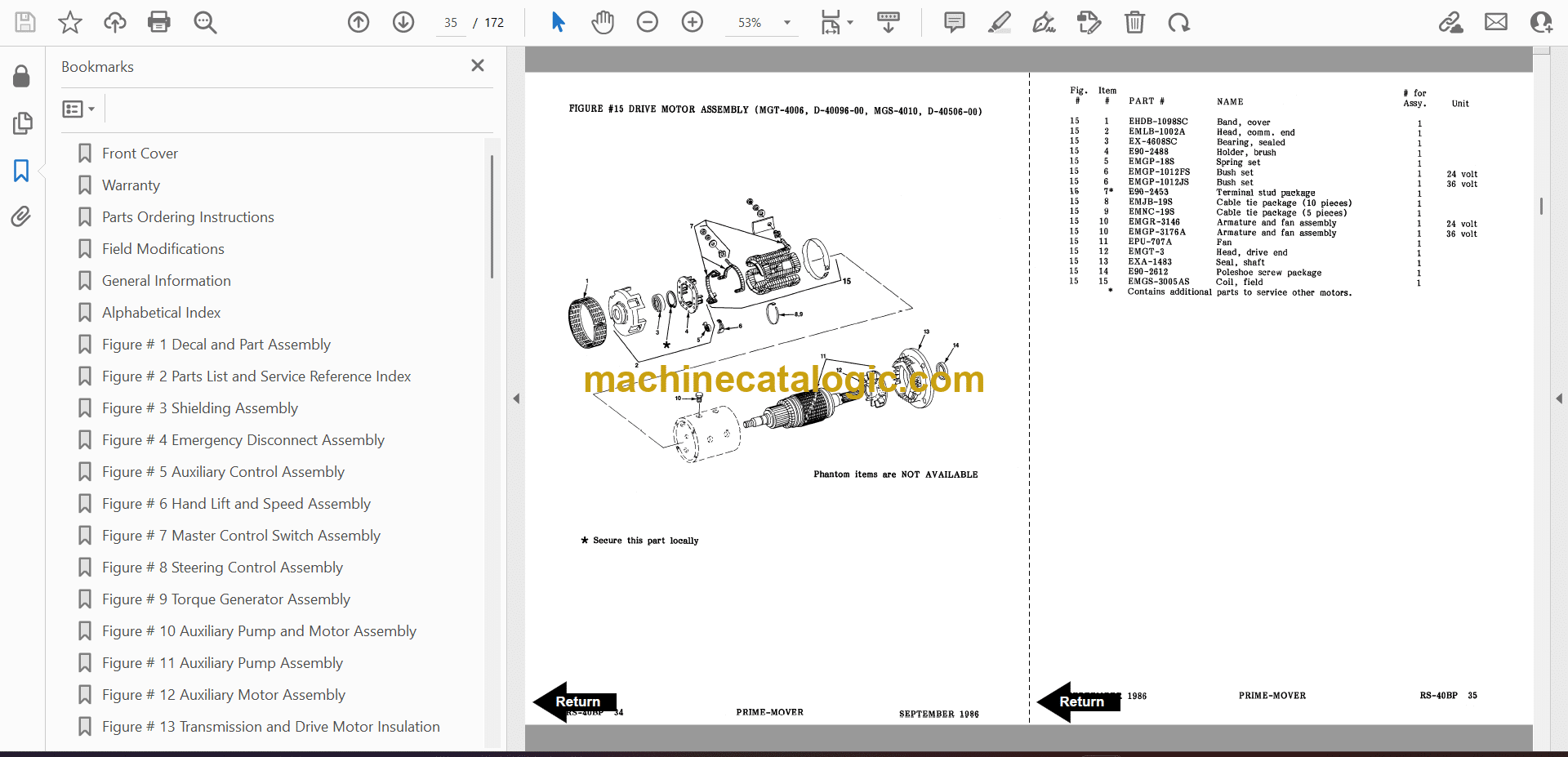
Figure # 15 Drive Motor Assembly
Figure # 16 Transmission Assembly
Figure # 17 Electrical Schematic
Figure # 18 Electrical Schematic Symbols
Figure # 19 Relay Wiring Harness Assembly
Figure # 20 Switch Relay Assembly
Figure # 21 Wiring Harness Assembly
Figure # 22 Wiring Assembly for Cold Storage
Figure # 23 2 Stage Mast Cable Assembly
Figure # 24 3 Stage Mast Cable Assembly
Figure # 25 Tilt with Sideshifter Cable Assembly
Figure # 26 Power Component Wiring
Figure # 27 SCR and Contactor Panel Assembly
Figure # 28 EV-1 SCR Control
Figure # 29 Transformer Assembly
Figure # 30 Rectifier Heat Sink Assembly
Figure # 31 G.E. Contactor Assembly
Figure # 32 G.E. Contactor Assembly
Figure # 33 Contactor Assembly
Figure # 34 Connector Assembly
Figure # 35 Warning Light Assembly
Figure # 36 Hydraulic Schematic
Figure # 37 Hydraulic Schematic Symbols
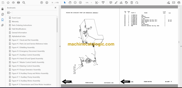
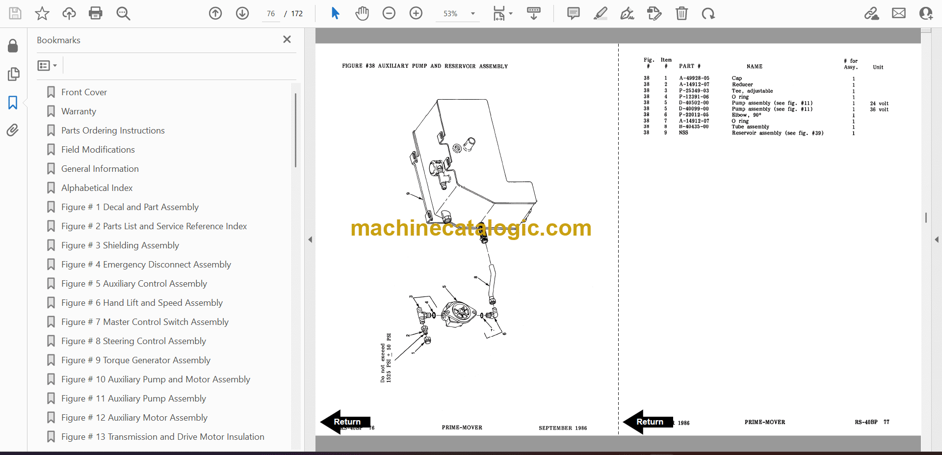
Figure # 38 Auxiliary Pump and Reservoir Assembly
Figure # 39 Hydraulic Reservoir Assembly
Figure # 40 Lift Pump and Motor Assembly
Figure # 41 Lift Pump and Motor Assembly
Figure # 42 Lift Motor Assembly
Figure # 43 24 Volt Lift Pump Assembly
Figure # 44 36 Volt Lift Pump Assembly
Figure # 45 Lift Control Valve Assembly
Figure # 46 Torque Generator and Filter Assembly
Figure # 47 Tube and Hose Assembly
Figure # 48 Auxiliary Control Valve Assembly
Figure # 49 2 Stage Cylinder and Reservoir Assembly
Figure # 50 2 Stage Cylinder Assembly
Figure # 51 3 Stage Cylinders and Reservoir Assembly
Figure # 52 3 Stage Staging Cylinder Assembly
Figure # 53 3 Stage Freelift Cylinder Assembly
Figure # 54 2 Stage Mast Hydraulic Hose Assembly
Figure # 55 3 Stage Mast Hydraulic Hose Assembly
Figure # 56 Tilt Cylinder and Related Parts
Figure # 57 Tilt Cylinder Assembly
Figure # 58 Sideshifter Cylinder with Tilt Assembly
Figure # 59 Sideshifter Cylinder Assembly
Figure # 60 Sideshifter Manifold Valve Assembly
Figure # 61 2 Stage Mast Installation Assembly
Figure # 62 2 Stage Inner Column Assembly
Figure # 63 2 Stage Outer Column Assembly
Figure # 64 2 Stage Cylinder Assembly and Related Parts
Figure # 65 Lift Frame Assembly
Figure # 66 Sideshifter Assembly
Figure # 67 Fork Assembly
Figure # 68 Three Stage Mast Installation Assembly
Figure # 69 3 Stage Outer Column Assembly
Figure # 70 3 Stage Intermediate Column Assembly
Figure # 71 3 Stage Inner Column Assembly
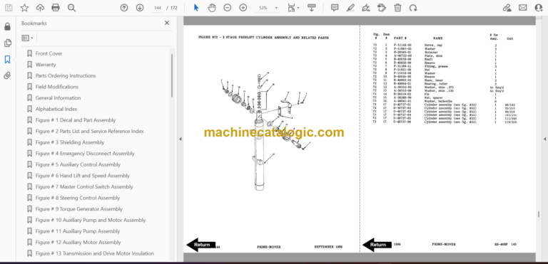
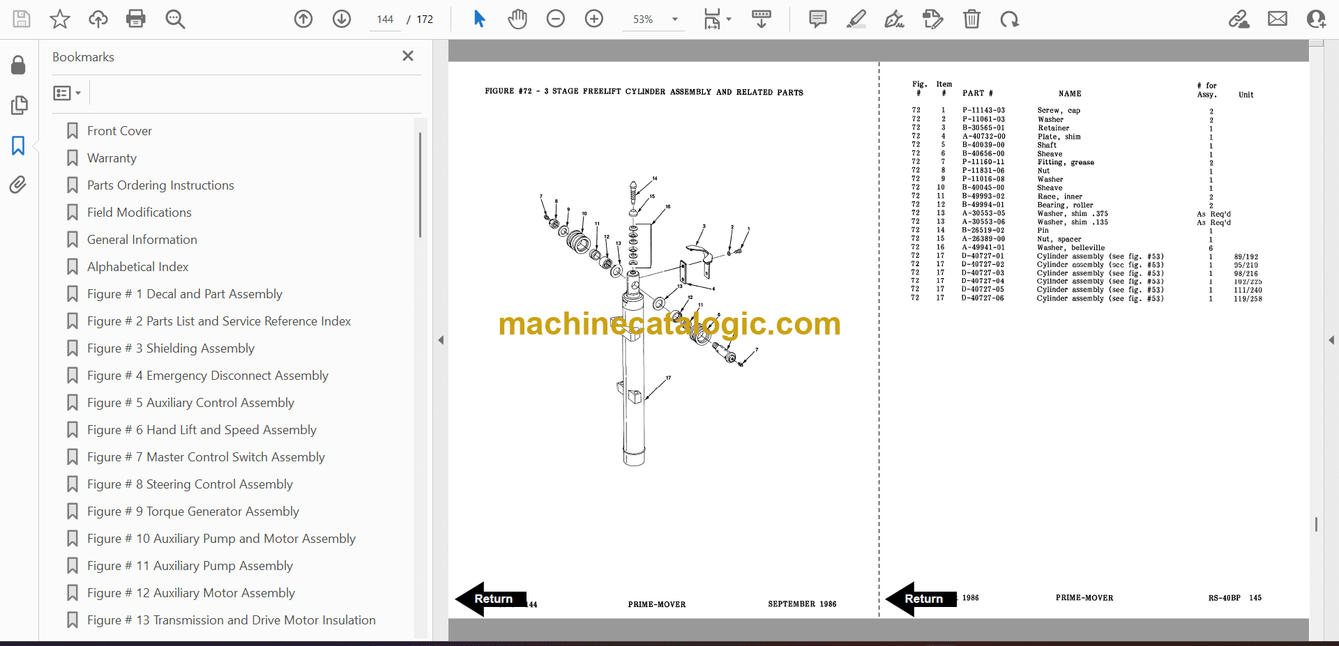
Figure # 72 3 Stage Freelift Cylinder Assembly and Related Parts
Figure # 73 Main Frame and Load Wheel Assembly
Figure # 74 Caster Assembly
Figure # 75 Single Load Wheel Assembly
Figure # 76 4″ High Outriggers Articulating Load Wheel Assembly
Figure # 77 Articulating Load Wheel Assembly
Figure # 78 Special Tools
Numerical Index
Back Cover
