Format: PDF (Printable Document)
File Language: English
Brand: BT
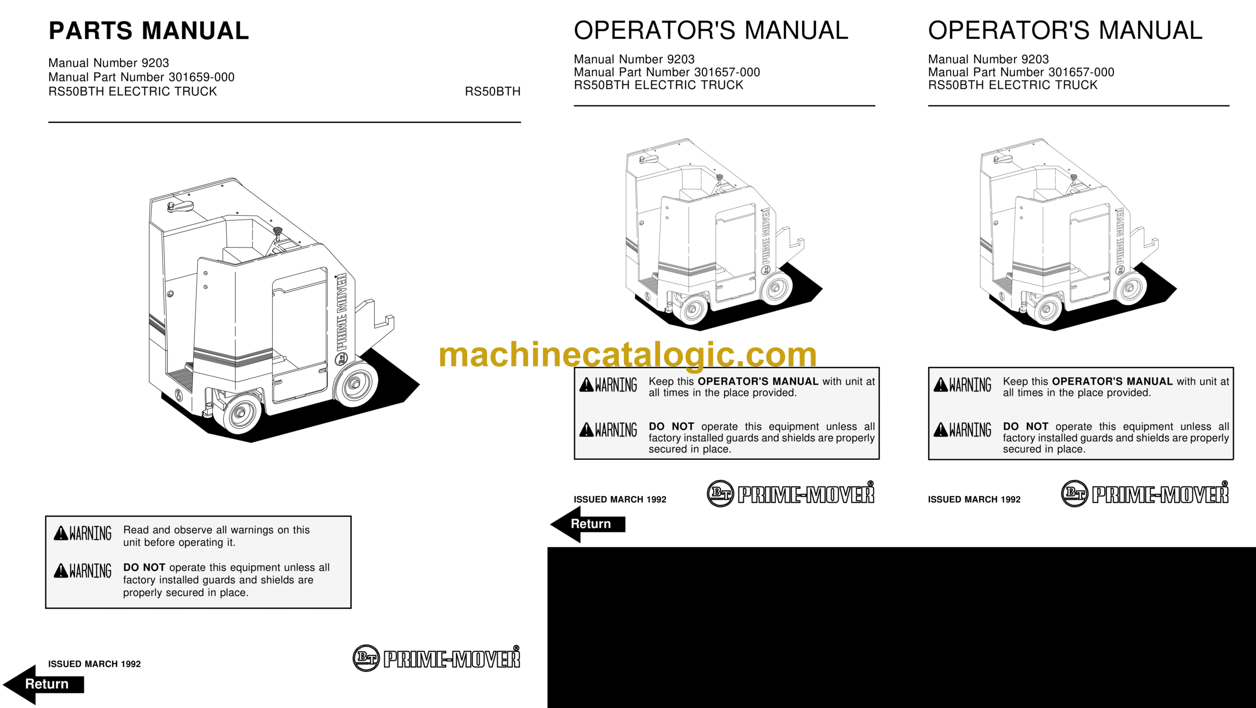
Model: RS50BTH Forklift
Type of Document: Operator and Parts Manual
$ 70
BT RS50BTH Forklift Operator and Parts Manual
Front Cover
Parts Ordering Instructions
General Information
Alphabetical Index
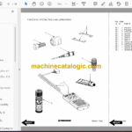
Figure # 0.1 Decals and Parts Assembly
Figure # 0.2 Parts List Index
Figure # 1.1 Transmission and Steering Installation
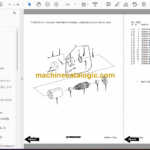
Figure # 1.2 Drive Motor Brake Assembly
Figure # 1.3 Transmission Assembly (40011-00) Part # I
Figure # 1.4 Transmission Assembly (40011-00) Part # II
Figure # 2.1 EV-100LX SCR Electrical Schematic
Figure # 2.2 EV-100LX SCR Electrical Schematic Symbols
Figure # 2.3 Wiring Harness Assembly
Figure # 2.4 EV-100LX Power Component Wiring
Figure # 2.5 EV-100LX TX SCR Control Panel Assembly (49399-00)
Figure # 2.6 EV-100LX Contactor Panel Assembly & Related Parts
Figure # 2.7 EV-100LX Contactor Panel Assembly (41757-01)
Figure # 2.8 EV-100LX SCR Forward & Rearward Contactor Assembly (27692-00)
Figure # 2.9 EV-100LX SCR 1A Contactor Assembly (27693-02)
Figure # 2.10 EV-100LX SCR Auxiliary Pump Contactor Assembly (300073-000)
Figure # 2.11 Power Connector Assembly (24 Volt, 49855-24)
Figure # 2.12 Drive Motor Assembly, (27901-00, 5BT1326B235) G.E.
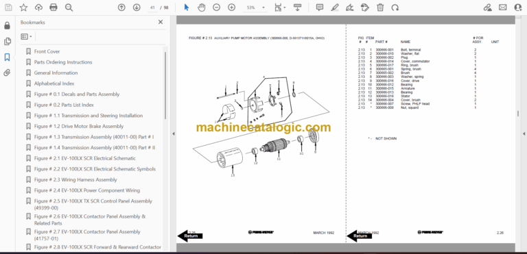
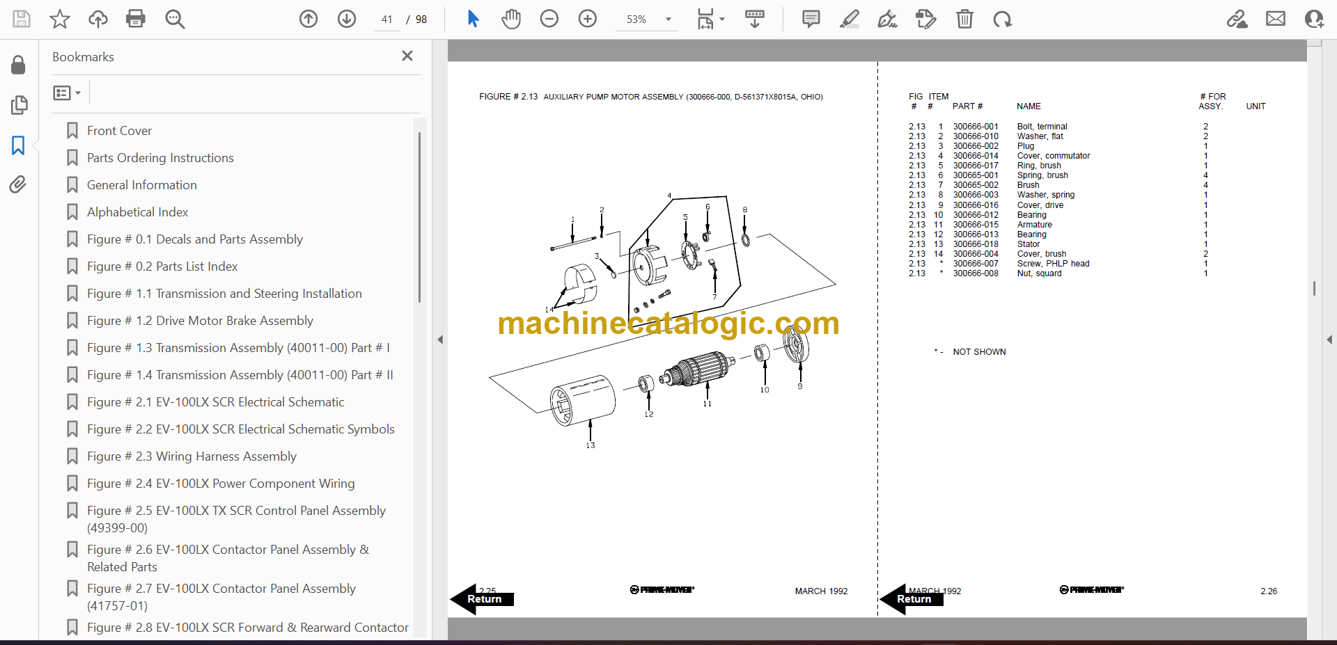
Figure # 2.13 Auxiliary Pump Motor Assembly (300666-000, D-561371X8015A, OHIO)
Figure # 3.1 Hydraulic Schematic
Figure # 3.2 Hydraulic Schematic Symbols
Figure # 3.3 Auxiliary Pump and Reservoir Assembly
Figure # 3.4 Auxiliary Control Valve Assembly (41331-00)
Figure # 3.5 Auxiliary Pump and Motor Assembly (300333-000)
Figure # 3.6 Auxiliary Pump Assembly
Figure # 3.7 Hydraulic Reservoir Assembly
Figure # 3.8 Steering Control Valve Assembly (40102-01)
Figure # 3.9 Steering Control Valve and Hose Assembly
Figure # 3.10 Steering Cylinder Assembly (41544-00)
Figure # 3.11 Clamp Cylinder and Related Parts
Figure # 3.12 Clamp Cylinder Assembly (41228-00)
Figure # 3.13 Brake Linkage and Cylinder Assembly
Figure # 3.14 Brake Master Cylinder (41336-00)
Figure # 3.15 Drive Motor Brake Cylinder (41337-00)
Figure # 3.16 Idler Wheel Brake Cylinder (41338-00)
Figure # 4.1 Shielding Assembly
Figure # 4.2 Emergency Disconnect Assembly
Figure # 4.3 Hand Clamp and Speed Control
Figure # 4.4 Steering Control Assembly
Figure # 4.5 Idler Wheel Installation
Figure # 4.6 Idler Wheel Assembly
Figure # 4.7 Main Frame and Load Wheel Assembly
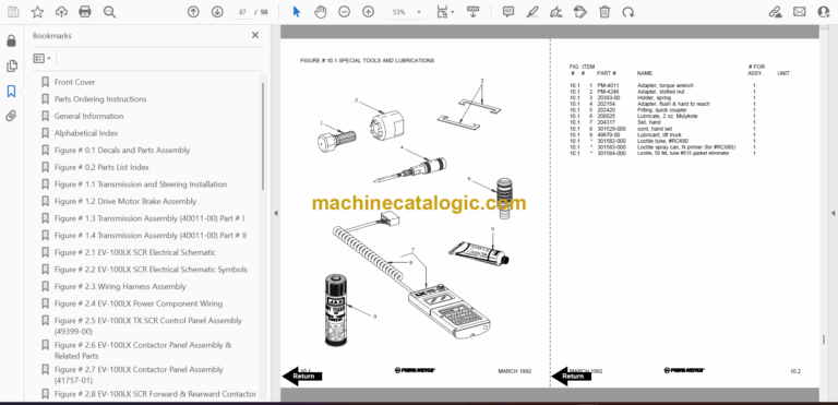
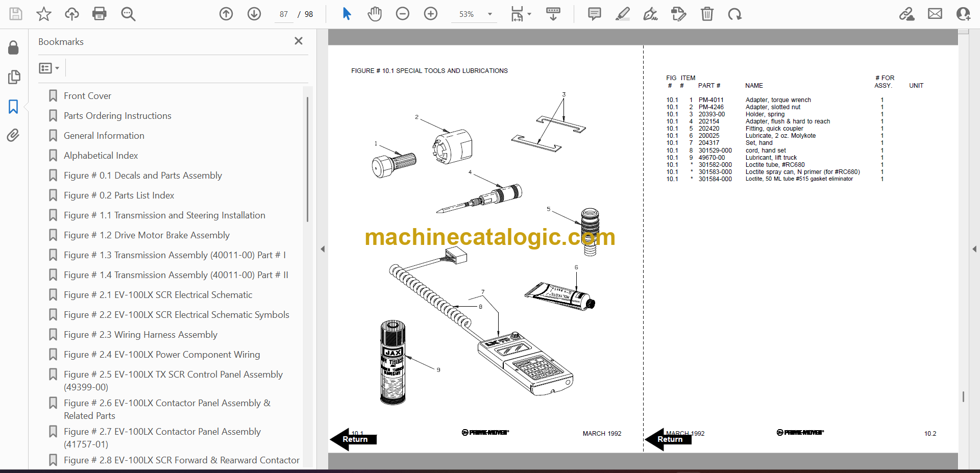
Figure # 10.1 Special Tools and Lubrications
Numerical Index
Back Cover
Front Cover
Important Notice
Foreword
Table of Contents
Drive Safely
Introduction
Preliminary Service
Operator
Operating Practices
Data Plate and Decals
Controls and Equipment
Before Operation Inspection
Controls and Equipment
Operation
Parking
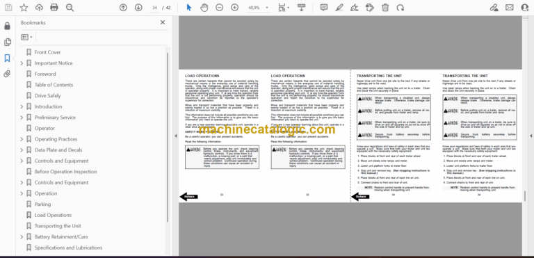
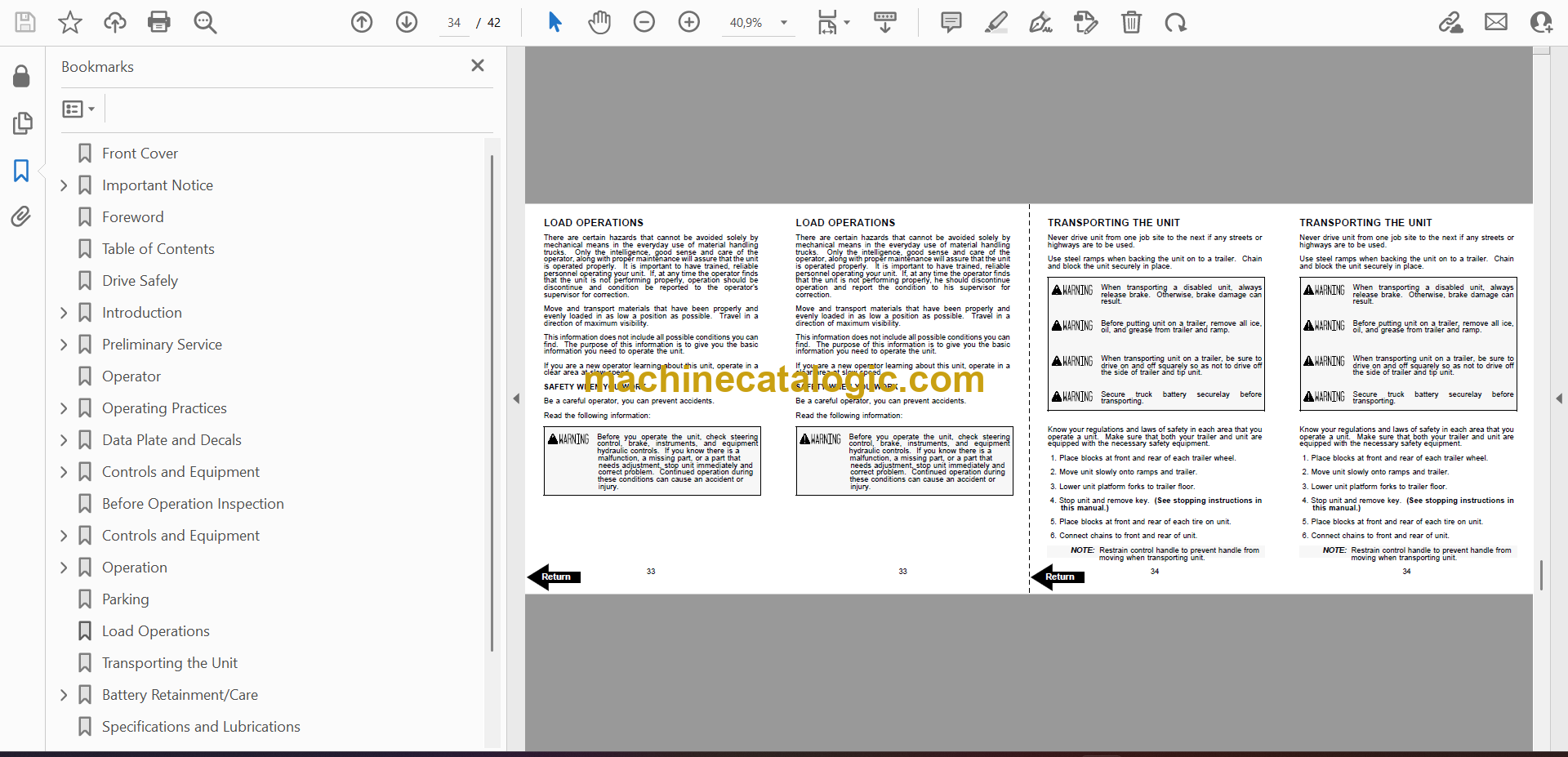
Load Operations
Transporting the Unit
Battery Retainment/Care
Specifications and Lubrications
Service Intervals
Field Modifications
Back Cover
