Format: PDF (Printable Document)
File Language: English
File Pages: 542
File Size: 26.67 MB (Speed Download Link)
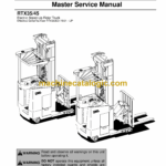
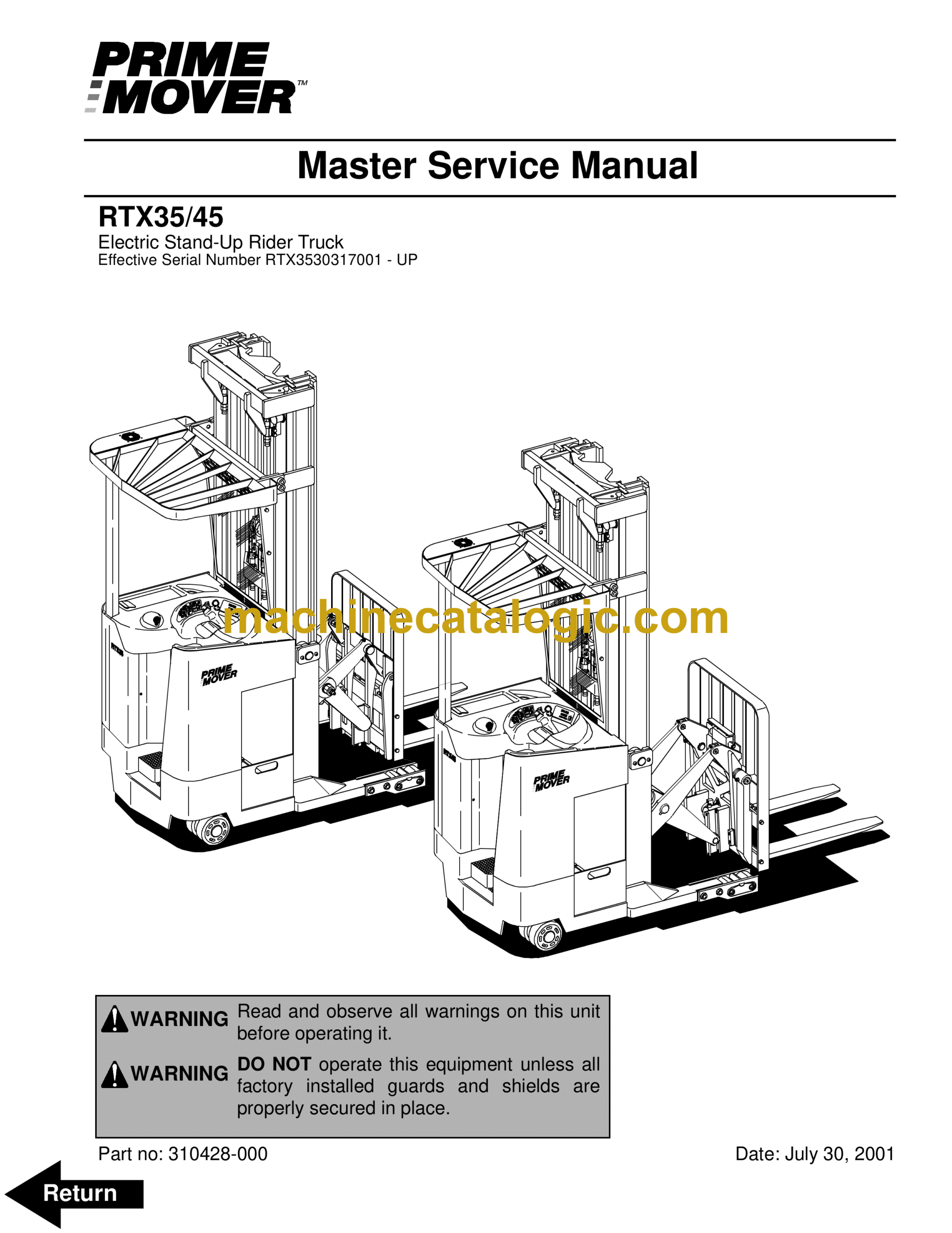
Brand: BT
Model: RTX35, RTX45
Part No: 310428-000
Type of Document: Master Service Manual
$ 40
BT Prime-Mover Standard Codes
Worksheet standard
C-Code List
Warning Symbols
1. Warning Levels
Prohibitory Symbols
NO SMOKING
OPEN FLAMES PROHIBITED
GENERAL PROHIBITION
1. Ordinance Symbols
Safety
1. General Safety
Battery Safety
Static Safety
1. Place a static discharge wrist strap around your wrist. Connect the ground lead to the wrist s…
2. Connect the ground clamp to an unpainted, grounded surface on the truck frame.
3. If removing or installing static-sensitive components, place them on a properly grounded stati…
4. To transport static-sensitive components, including failed components being returned, place th…
Welding Safety
Introduction, Service Manual
Contents, Section M
1. Machine Information
General Product Information
1. Truck Presentation
2. Main Components
3. Grease Point Location
4. Mast Adjustment Points
Inch (SAE) and Metric Fasteners
1. Introduction
2. Nomenclature, Threads
3. Strength Identification
4. Conversion of Metric and English Units
Technical Service Data
MODEL
Series – DC
Series – DC
5 hp/3.725 kw (24 volt drive motor) 6.25 hp/4.66 kw (36 volt drive motor) 16hp/11.9 kw (36 volt l…
1 hour continuous
1 hour continuous
0.8 inch (20 mm)
0.8 inch (20 mm)
2.90 inches (74 mm)
2.90 inches (74 mm)
6.4 oz. (180 grams)
6.4 oz. (180 grams)
Vertical motor spiral-bevel output
Vertical motor spiral-bevel output
17.57
17.57
1 gallons (3.79 liters)
1 gallons (3.79 liters)
SAE 80W90
SAE 80W/90
ATF
SAE 80W90
SAE 80W/90
ATF
13.5 x 5.5 x 10.0 inches (343 x 140 x 254 mm)
13.5 x 5.5 x 10.0 inches (343 x 140 x 254 mm)
1600 lb battery 14.5” BC – 6735 (3054) 2000 lb battery 16.5” BC – 4315 (1959)
2000 lb battery 16.5” BC – 4750 (2156) 2400 lb battery 21” BC – 4910 (2229)
1600 lb battery 14.5” BC – 3240 (1471) 2000 lb battery 16.5” BC – 3430 (1557)
2000 lb battery 16.5” BC – 3780 (1716) 2400 lb battery 21” BC – 4025 (1827)
95 ft-lb (130 N•m)
95 ft-lb (130 N•m)
5.0 x 3.6 inches (127 x 91 mm)
5.0 x 3.6 inches (127 x 91 mm)
1600 lb battery 14.5” BC – 6860 (3114 2000 lb battery 16.5” BC – 7145 (3244)
2000 lb battery 16.5” BC – 8595 (3902) 2400 lb battery 21” BC – 8690 (3945)
300 Amp 400 Amp
Not Applicable (N/A) 425 Amp
24V -1400 empty-750 loaded 36V – 2100 empty-1500 loaded
36V – 2250 empty-1450 loaded
36 volt 11.6 HP with 20% duty cycle
20% on 5 minute cycles
0.8 inch (20 mm)
0.62 inch (16 mm)
2.90 inches (74 mm)
2.80 inches (72 mm)
6.4 oz (180 grams)
40 oz (1120 grams)
2450 psi (16890 kPa)
2450 psi (16890 kPa)
11 cc upper/4 cc lower
16 cc upper/4 cc lower 8 cc upper/4 cc lower
N/A
23 cc upper/4 cc lower 11 cc upper/4 cc lower
5 gallons (19 liters)
5 gallons (19 liters)
Sunoco TH
ATF
Texaco 15
Sunoco TH
ATF
Texaco 15
250 Amp
250 Amp
425 Amp
355 Amp
N/A
500 Amp
10 Amp
10 Amp
14.4 x 38.8 x 32.0 inches
(366 x 986 x 813 mm)
16.4 x 38.8 x 32.0 inches
(417 x 986 x 813 mm)
16.4 x 38.8 x 32.0 inches
(417 x 986 x 813 mm)
20.9 x 38.8 x 32.0 inches
(531 x 986 x 813 mm)
1020 Amp hours
1000 Amp hours 875 Amp hours
N/A
1000 Amp hours 875 Amp hours
14.5 inches (368 mm) 1600 lb (726 kg)
(2300 lb / 1044 kg)
16.5 inches (419 mm) 2000 lb (908 kg)
(2300 lb / 1044 kg)
16.5 inches (419 mm) 2000 lb (908 kg)
(2300 lb / 1044 kg)
21.0 inches (533 mm) 2400 lb (1089 kg)
(2900 lb (1317 kg)
6.0 mph (9.65 kph)
6.5 mph (10.46 kph)
N/A
6.5 mph (10.46 kph)
5.5 mph (8.85 kph)
6.0 mph (9.65 kph)
N/A
6.0 mph (9.65 kph)
57 fpm (17.37 m/min.)
80 fpm (24.4 m/min.)
N/A
95 fpm (29 m/min.)
34 fpm (10.4 m/min.)
60 fpm (18.3 m/min.)
N/A
60 fpm (18.3 m/min.)
80 fpm (24.4 m/min.)
90 fpm (27.5 m/min.)
80 fpm (24.4 m/min.)
95 fpm (29 m/min.)
95 Amps
80 Amps
N/A 90 Amps
115 Amps
95 Amps
N/A
105 Amps
170 Amps
215 Amps
145 Amps
200 Amps
235 Amps
170 Amps
N/A
310 Amps
225 Amps
N/A
330 Amps
240 Amps
325 Amps
395 Amps
270 Amps
355 Amps
430 Amps
300 Amps
N/A
530 Amps
390 Amps
N/A
550 Amps
395 Amps
Ordering Spare Parts
1. Locate the fault on the truck.
2. Identify truck model, serial number, and battery voltage.
3. Locate the page with the exploded diagram and find the item number for the part required.
4. Locate the item number in the table. Select the column for the actual truck model and serial n…
5. Note the part number.
6. Call your local BT Prime-Mover Dealer and indicate the part number.
7. If the model, serial number, or the article number cannot be found on the truck, call your loc…
Contents, Section P
1. Planned Maintenance
Introduction, Maintenance
1. Safe Jacking Procedure
2. Lubricants
Service Schedule
1. Planned Maintenance Schedule
2. Planned Maintenance Procedures
Lubrication Chart
Interval/Running Hours
Lubricant
Oil and Grease Specifications
1. Approved Oils and Grease
Contents, Section S
1. Service Instructions
Troubleshooting Guidelines
1. General
2. Electrical
3. Hydraulic
4. Definitions
Chassis
1. General
2. Top Console
3. Motor Compartment Door
4. Left Side Panel (Exterior)
5. Left Operator Compartment Panel
6. Main Electronic Card Panel
7. Floor Board
8. Clipboard
Battery Retainer Plates and Rollers
f
1. Battery Retainer Plates
2. Battery Rollers
Mounting Points
1. Drive Motor
2. Pump Motor
3. Transmission
Driver Controls
1. Handle Interface Module
2. Control Handle
Brake Pedal (RTX35)
1. Pedal Removal
2. Pedal Bearing Replacement
3. Pedal Adjustment
Brake Pedal (RTX45)
1. Pedal Removal
2. Pedal Bearing Replacement
3. Pedal Adjustment
Internal Fittings
1. Operator Fan
Guards
1. Overhead Guard
Decals
1. Decal with Protective Sheet
2. Decal without Protective Sheet
Steering Motor
1. Removal
2. Installation
3. Steering Motor Gear Replacement
Fan Motor
1. Upper Electrical Compartment Fan
2. Operator Fan
Motor Maintenance Schedule/Troubleshooting
1. General Information
2. Operating Conditions
3. Troubleshooting
Pump Motor (RTX35)
1. Component Repair
2. Motor Inspection
Pump Motor (RTX 45)
1. Component Repair
2. Motor Inspection
Drive Motor
1. Motor Disassembly
2. Motor Inspection
Transmission.
1. Axle Sealing Ring
2. Leakage
3. Wheel Bolt
Electromagnetic Brake
1. Removal
2. Installation
3. Adjustments
4. Coil Check On Brake
5. Electromagnetic Brake, Armature and Magnetic Coil
6. Brake Friction Plate
Drive Wheel
1. Removal
2. Installation
3. Tire Pressing Procedure
Non-Braking Caster Assembly
1. Caster Pivot
2. Thrust Bearing
3. Caster Springs
4. Caster Stops
Non-Braking Caster Wheels
1. Removal
2. Installation
Braking Caster Assembly
1. Removal
Braking Caster Wheel Assembly
1. Removal
2. Installation
Tandem Load Wheels
1. Removal
2. Installation
Single Load Wheels
1. Removal
2. Installation
Steering Wheel
1. Removal
2. Installation
Steer Tach
1. Removal
2. Installation
Steering Bearing
1. Removal
2. Installation
Electrical Functions
1. General
2. Start Up
3. Steering Components
4. Brake Release
5. Travel Request, Forks First
6. Travel Request, Forks Trailing
7. Plug Braking
8. 12-Volt Power Supply
9. 7.35-Volt Power Supplies
10. Limit Switches
11. Height Indicator
12. Drive Motor Brush Wear Indicator Switches
13. Pump Motor Brush Wear Indicator Switches
14. Safety Check
15. Shunt Power Cable
Electrical Symbols
Electrical Schematics
1. Circuit Diagram 1 (12)
2. Circuit Diagram 2 (12)
3. Circuit Diagram 3 (12)
4. Circuit Diagram 4 (12)
5. Circuit Diagram 5 (12)
6. Circuit Diagram 6 (12)
7. Circuit Diagram 7 (12)
8. Circuit Diagram 8 (12)
9. Circuit Diagram 9 (12)
10. Circuit Diagram 10 (12)
11. Circuit Diagram 11 (12)
12. Circuit Diagram 12 (12)
Battery
1. Removal
2. Installation
3. Battery Maintenance
4. Storage
5. Battery History Record
Light Assemblies
1. Overhead Guard Lights (Option)
2. Warning Lights (Option)
3. Working Lights (Option)
4. Travel/Back-up Alarm (Option)
Horn
1. Removal
2. Installation
Battery Connector
1. Location
2. Inspection
3. Installation
Start/Stop Switches
1. General
2. Key Switch (S17)
3. Emergency Disconnect Switch (S21)
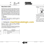
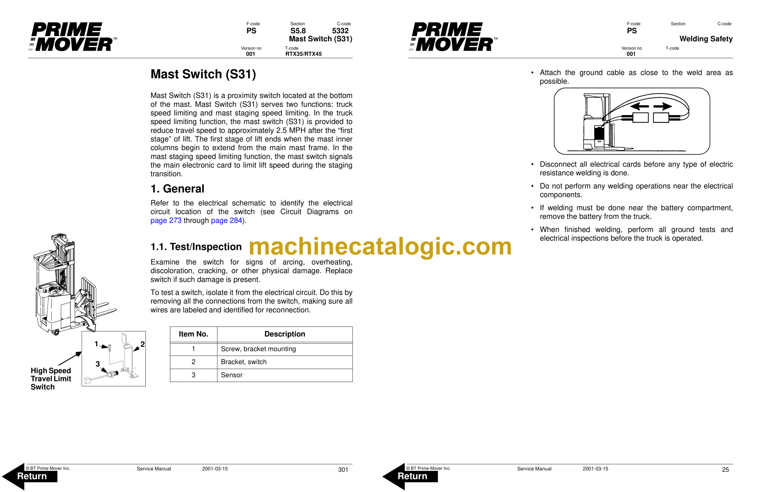
Mast Switch (S31)
1. General
2. Adjustment
3. Removal
4. Installation
Control Cable and Harness
1. Fuses
2. Wiring
3. Auxiliary Power Hook-up for On-board Terminal
Contactors
1. General
2. Directional Contactors
3. Lift Bypass Contactor
4. Battery Cut-out Contactor
Transistor Panel (Drive)
1. Motor Connections
2. Circuit Check.
Transistor Panel (Pump)
1. Motor Connections
Micro Switches
1. General
2. Lift Limit Override Switch (S33)
3. Optional Light and Fan Switches (S96, S97 and S99)
Main Electronic Card
1. Removal
2. Installation
3. Connectivity to Truck
4. Display
5. Warning/Caution codes
6. Error codes
7. Parameters
8. Running time
9. Programming Parameters
10. RV2 Adjustment Procedure
11. Adjustment Procedures for Setting Brake Switch and Brake Transducer
Switches and Sensors
1. General
2. Platform (Right Foot) Switch (S23)
3. Staging Switch (S45)
4. Wheel Direction Sensor
5. Steer Stop Proximity Sensor A and Sensor B
6. Drive Motor Speed/Direction Sensors
Hydraulic System
1. Operation
2. RTX35 Hydraulic Schematic
3. RTX45 Hydraulic Schematic
Hydraulic Fluid
1. Hydraulic Fluid Selection
2. Changing Hydraulic System Fluid
3. System Draining
4. System Refilling
5. Bleeding Hydraulic System
Hydraulic Tank
1. Removal
2. Installation
Hydraulic Filter and Adapter
1. Hydraulic Filter
2. Hydraulic Filter Adapter
Hydraulic Pump
1. Removal
2. Pump Disassembly
3. Parts Inspection
4. Pump Reassembly
5. Testing
Control Valve
1. Removal
2. Installation
3. Repair
Staging Cylinder, 3 Stage
1. Staging Cylinder Repair
Freelift Cylinder, 3 Stage
1. Freelift Cylinder Repair
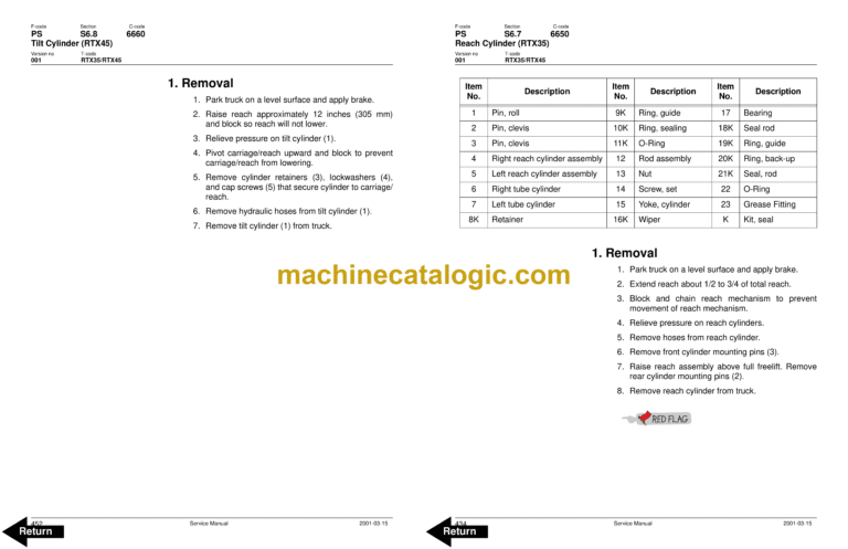
Reach Cylinder (RTX35)
1. Removal
2. Disassembly
3. Inspection
4. Assembly
5. Installation
Reach Cylinder (RTX45)
1. Removal
2. Disassembly
3. Inspection
4. Assembly
5. Installation
Tilt Cylinder (RTX35)
1. Removal
Tilt Cylinder (RTX45)
1. Removal
Mast, 3 Stage (RTX35)
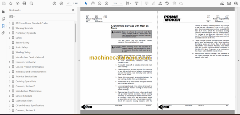
1. Shimming Carriage with Mast on Truck
2. Three Stage Mast
Mast, 3 Stage (RTX45)
1. Shimming Carriage with Mast on Truck
2. Three Stage Mast
Lift Chain
1. Lift Chain Adjustment
2. Lift Chain Maintenance
3. Lift Chain Inspection
4. Lift Chain Lubrication
5. Lift Chain Replacement
Lifting Gear (Crosshead) (RTX35)
1. Lifting Gear Repair
Lifting Gear (Crosshead) (RTX45)
1. Lifting Gear Repair
Sideshifter
1. Mounting Instructions
2. Operation
3. Maintenance
4. Troubleshooting
Reach, Single (RTX35)
1. Maintenance
2. Reach Repair
3. Carriage Bumpers
4. Fork Carriage Pivot Pins
5. Carriage Roller Bearings
Reach, Single (RTX45)
1. Maintenance
2. Reach Repair
3. Reach Carriage Wear Strip
4. Fork Carriage Pivot Pins
5. Carriage Bumpers
6. Carriage Roller Bearings
Height Indication
1. General
2. Operation
3. Error Code 13
Height Indicator (RTX35)
1. Pulse sensor
Height Indicator (RTX45)
1. Pulse sensor
Load Backrest
1. Removal
2. Installation

