Format: PDF (Printable Document)
File Language: English
File Pages: 222
File Size: 13.12 MB (Speed Download Link)
Brand: BT
Model: SPE125, SPE160, SPE135S, SPE125L, SPE160L Electric Stacker
Part No: 711956-
Type of Document: Master Service Manual
$ 40
Contents
2- Presentation of the truck – M2
2.1 Intended application of the truck
2.2 Forbidden application of the truck
2.3 Truck data
2.4 Truck dimensions
2.5 Identification plate
2.6 Capacity plate
2.7 Addition and information plate
2.8 Capacity plate for double pallet handling
2.9 Main components
2.10 Warning and information plates
3- Technical data – M4
3.1 General tightening torques
4- Installation and maintenance instructions – P1
4.1 Truck installation
4.2 Introduction, maintenance
4.3 Cleaning and washing
4.4 Safe lifting
5- Maintenance schedule – P2
5.1 Lubrication chart
6- Oil and grease specification – P3
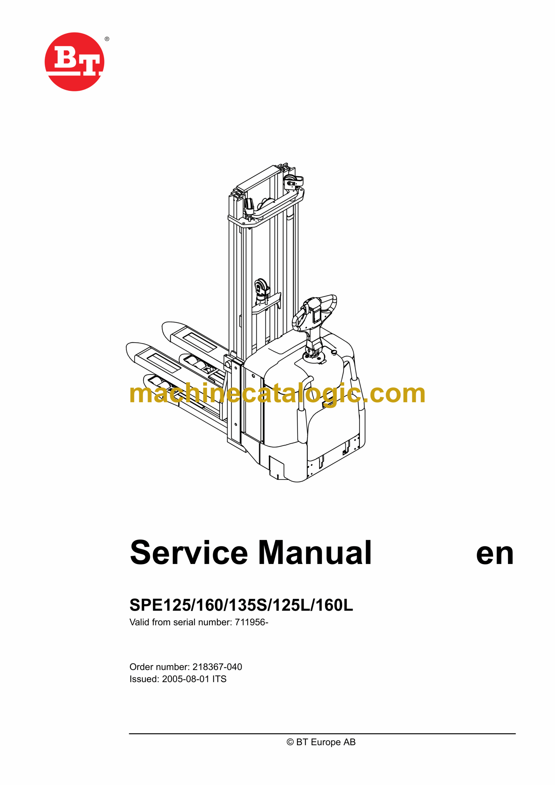
7- Tools – P4
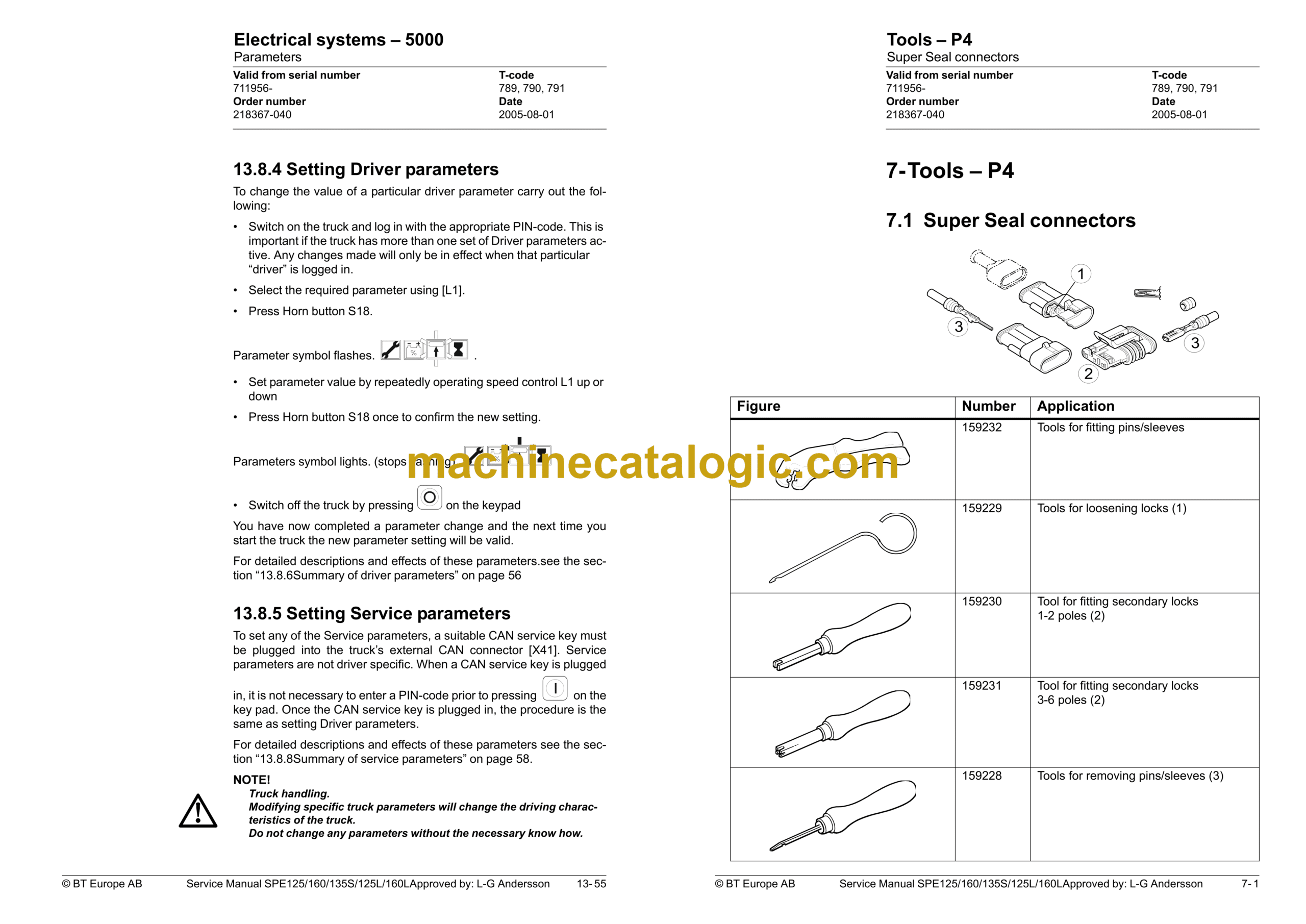
7.1 Super Seal connectors
7.2 AMP connectors
7.3 Molex connectors
7.4 Grease guns
7.5 Other tools
8- Support arms – 0350
8.1 General
8.2 Main components
8.3 Maintenance
8.4 Adjusting the support arm width
8.5 Support arm replacement
9- Electric drive motor – 1760
9.1 Included components
9.2 Disassembly/assembly of the truck motor
9.3 Service/repairs
9.4 Technical data
10- Drive unit/gear – 2550
10.1 Included components
10.2 Leakage from top cover
10.3 Replacing the drive axle jointing ring
11- Electromagnetic brake – 3370
11.1 Main components of the brake
11.2 Maintenance
12- Electrical steering system – 4300
12.1 Electrical steering servo
12.2 Steering servo components
12.3 Adjustment
13- Electrical systems – 5000
13.1 Electrical equipment overview
13.2 Equipment list and electrical diagram
13.3 Functional description
13.4 Speed limitation
13.5 Hour meter and battery condition
13.6 Diagnostic and troubleshooting
13.7 Part numbers
13.8 Parameters
13.9 Technical specifications – Curtis 1243
14- Hydraulic system – 6000
14.1 Hydraulic diagram
14.2 Main components
14.3 Description
15- Main lift chain system – 7120
15.1 General
15.2 Checking the chain setting
15.3 Chain inspection
15.4 Cleaning
15.5 Lubrication
16- TruckCom
16.1 General
16.2 Connection
16.3 Layout
16.4 Connection function
16.5 Disconnection function
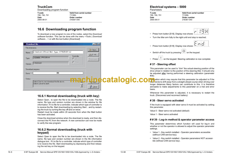
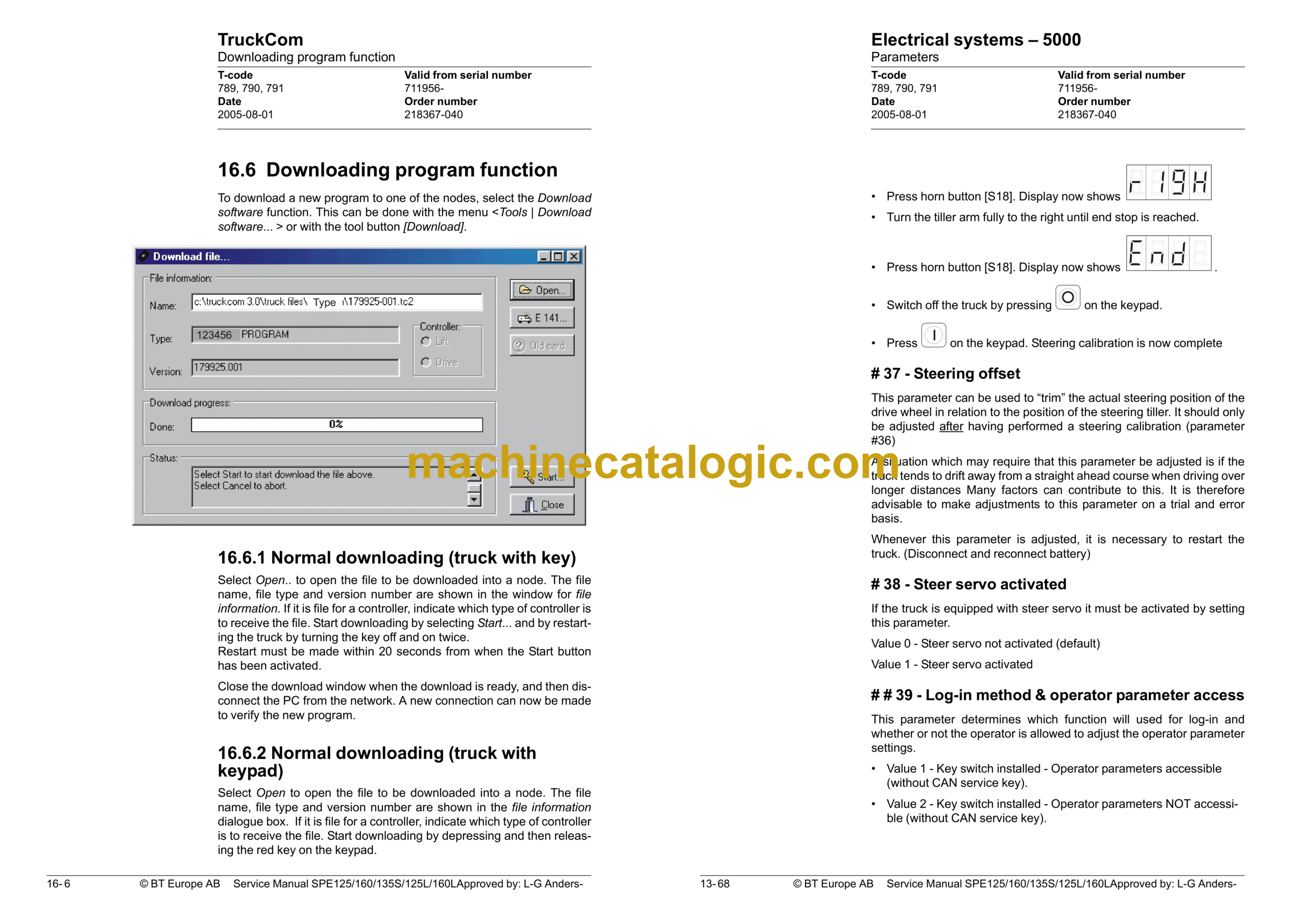
16.6 Downloading program function
16.7 Truck report function
16.8 Parameters function
16.9 Diagnostics function
16.10 Other menu functions
16.11 Specifications
16.12 Installation
17- Destruction instructions – M6
17.1 General
17.2 Procedure
17.3 Abbreviations
17.4 Sorting
17.5 Chassis (0300)
17.6 Hoods, covers (0340)
17.7 Fork structure (low-lifter) (0380)
17.8 Travel platform including mount (0560)
17.9 Overhead guard (option) (0810)
17.10 Operator protective device (0840)
17.11 Electric pump motor (1710)
17.12 Electric travel drive motor (1760)
17.13 Drive unit/gear (2550)
17.14 Wheels (3500)
17.15 Steering arm (4110)
17.16 Steering arm (4110)
17.17 General electric equipment (5100)
17.18 Cabling (5590)
17.19 Steering and protective electronics (5700)
17.20 Lift/lowering sensor (5820) and safety sensor (5830)
17.21 Hydraulic unit (6100)
17.22 Main mast (7100)
17.23 Chassis-mounted hydraulic oil lines (6230) (and main lift cylinder (6610) )
17.24 Battery charger connector (9380)

