Format: PDF (Printable Document)
File Language: English
File Pages: 110
File Size: 3.84 MB (Speed Download Link)
Brand: BT
Model: SSE160D
Type of Document: Master Service Manual
$ 40
1- Contents
2- Technical data
2.1 General tightening torques
2.1.1 Galvanised, non-oiled bolts
2.1.2 Untreated, oiled bolts
3- Maintenance
3.1 Introduction
3.2 Safety regulations during maintenance work
3.3 Cleaning and washing
3.3.1 Cleaning the exterior
3.3.2 Cleaning the motor compartment
3.3.3 Electrical components
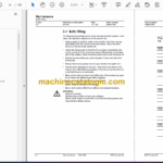
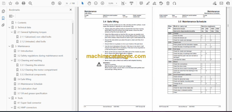
3.4 Safe lifting
3.5 Maintenance Schedule
3.6 Lubrication chart
3.7 Oil and grease specification
4- Tools
4.1 Super Seal connector
4.2 AMP connectors
4.2.1 AMP connector Multilock series 040
4.3 Molex connector
4.4 Other tools
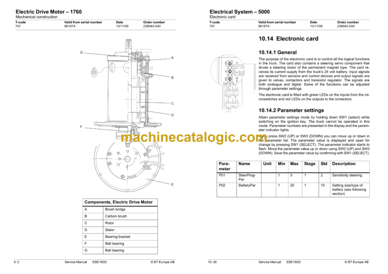
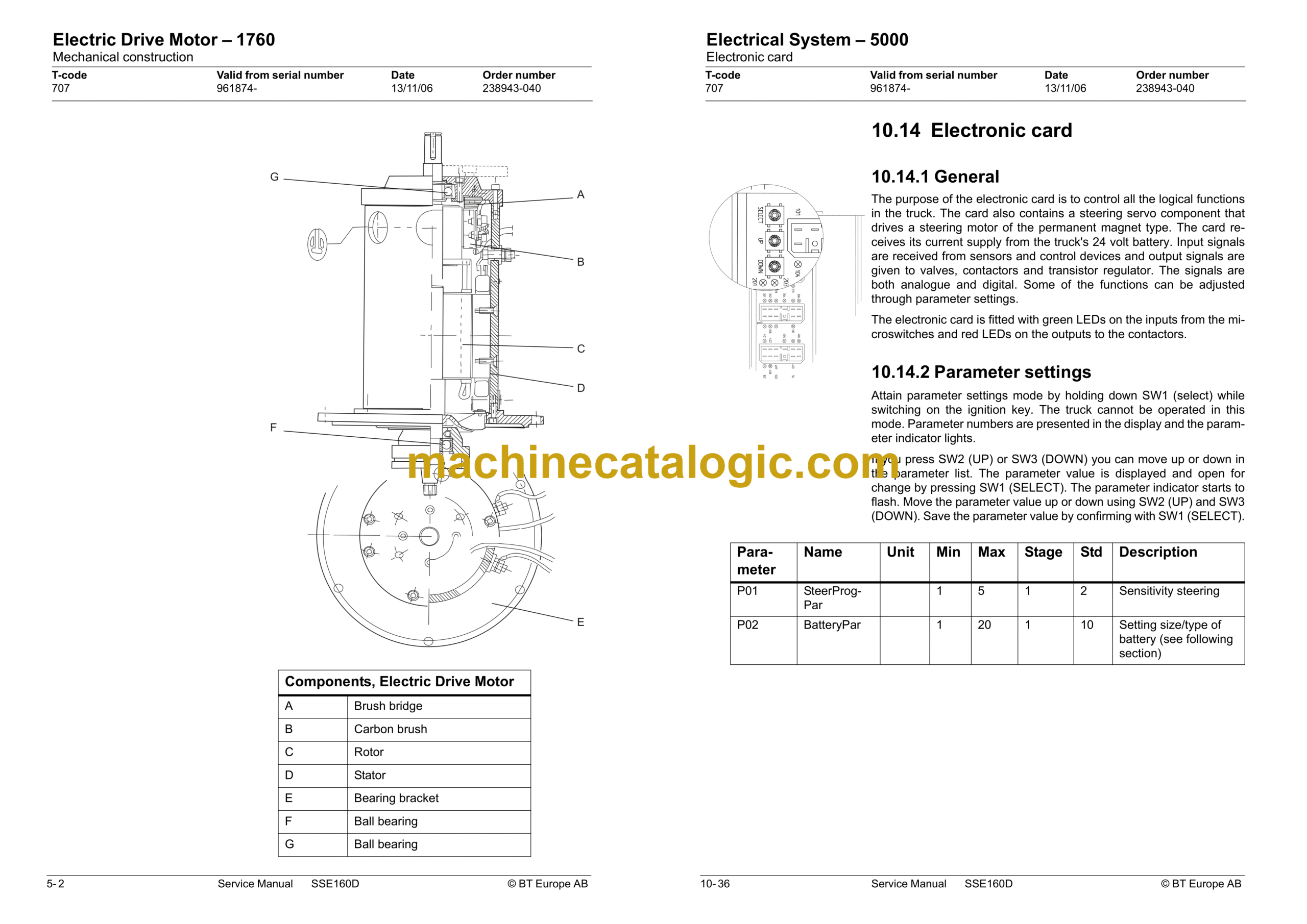
5- Electric Drive Motor – 1760
5.1 General
5.2 Mechanical construction
5.3 Special tools
5.4 Removal/Refitting
5.4.1 Removing the motor from the truck
5.4.2 Refitting the motor in the truck
5.5 Service and repairs
5.5.1 Cleaning
5.5.2 Dismantling the motor
5.5.3 Reassembling the motor
5.5.4 Armature bearings
5.5.5 Replacing the drive end bearing
5.5.6 Replacing the commutator end bearing
6- Drive/Transmission Assembly – 2550
6.1 General
6.2 Component parts
6.3 Dismantling the drive assembly from the truck
6.4 Refitting the drive assembly in the truck
6.5 Oil check after oil change
6.5.1 Checking/refilling the oil
6.5.2 Changing the oil
6.6 Replacing the gasket
6.6.1 Dismantling
6.6.2 Assembly
6.7 Leakage from the upper cover
6.8 Replacing the stud
7- Electromagnetic brake – 3370
7.1 Brake’s main components
7.2 Maintenance
7.3 Adjusting the gap
7.3.1 Execute the following procedure for adjusting the gap
7.4 Replacing the brake disc
8- Support/caster wheel – 3500
8.1 Main components
9- Electric Wheel Steering – 4000
9.1 General
9.2 Components
9.3 Replacing the steering generator
9.3.1 Dismantling
9.3.2 Assembly
10- Electrical System – 5000
10.1 Electrical components
10.2 List of components
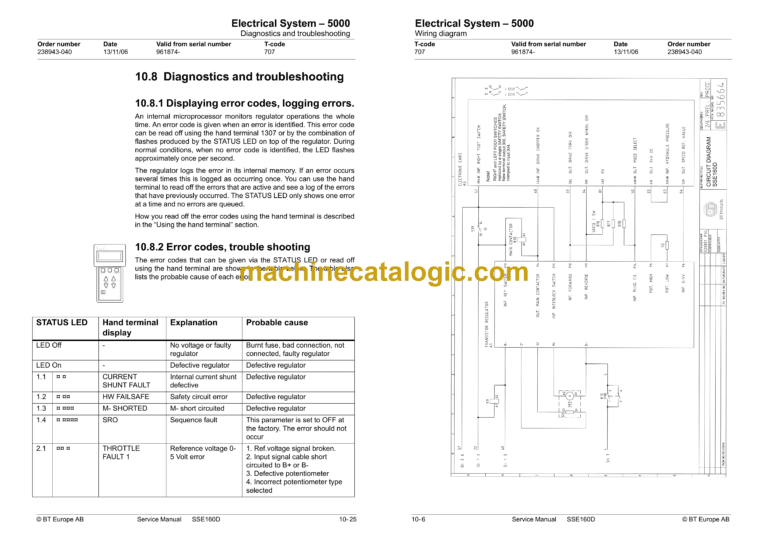
10.3 Wiring diagram
10.3.1 Symbol list
10.3.2 Wiring diagram
10.4 Functional description
10.4.1 General
10.4.2 Key in Position O
10.4.3 Key in Position I
10.4.4 Driving in drive wheel direction
10.4.5 Driving in fork direction
10.5 Motor braking, reversing
10.5.1 Brake
10.5.2 Lifting the forks
10.5.3 Lowering the forks
10.5.4 Lifting the support arm
10.5.5 Lower the support arm
10.5.6 Horn
10.6 Transistor regulator
10.6.1 General
10.6.2 Connections
10.6.3 Connectors for logics
10.7 Parameters
10.7.1 Modes 1 and 2
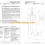
10.8 Diagnostics and troubleshooting
10.8.1 Displaying error codes, logging errors.
10.8.2 Error codes, trouble shooting
10.8.3 Resetting errors
10.9 Maintenance
10.9.1 Safety
10.9.2 Cleaning
10.10 Technical specifications Curtis 1243
10.11 Hand terminal 1307
10.12 Using the hand terminal
10.13 Checking and adjusting parameters
10.13.1 Using PROGRAM MODE
10.13.2 Using MORE INFO in PROGRAM MODE
10.13.3 Using SPECIAL PROGRAM MODE
10.13.4 Using TEST MODE
10.13.5 Using DIAGNOSTIC MODE
10.13.6 SPECIAL DIAGNOSTICS MODE
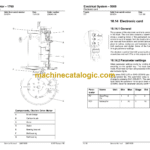
10.14 Electronic card
10.14.1 General
10.14.2 Parameter settings
10.14.3 Setting of battery size/type
10.15 Short connections and LEDs
10.16 Error codes
11- Hydraulic System – 6000
11.1 General
11.2 Hydraulic diagram and main components
11.3 Functional description
11.3.1 Lifting the forks
11.3.2 Lowering the forks
11.3.3 Working pressure
11.3.4 Overflow valve
12- Lift Frame – 7000
12.1 Adjusting the dimension between guide and frame
12.2 Lubricating the flanges and webs
12.3 Main lift chain system
12.3.1 Checking the chain setting
12.3.2 Check of chain
12.3.3 Noise
12.3.4 Surface rust
12.3.5 Rusty links
12.3.6 Stiff links
12.3.7 Bolt rotation
12.3.8 Loose bolts
12.3.9 Outline wear
12.3.10 Elongation
12.3.11 Damage
12.3.12 Damaged discs
12.3.13 Damaged bolts
12.3.14 Dirty chain
12.4 Cleaning
12.5 Lubrication
Lubrication intervals:
