Format: PDF (Printable Document)
File Language: English
File Pages: 294
File Size: 10.80 MB (Speed Download Link)
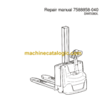
Brand: BT
Model: SWE080L Electric Stacker
Type of Document: Repair Manual
$ 40
1. Contents
2. General introduction
2.1 How to use this manual
2.2 Warning levels and symbols
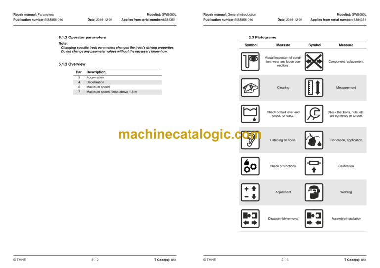
2.3 Pictograms
3. General safety rules
3.1 Work safety
3.2 Electrical system
3.3 Safe lifting
3.4 Truck modifications
4. Operation and connection sequences
Symbols on keypad and display
4.1 Battery is connected
4.2 Login via keypad
4.3 Tiller arm lowered for driving
4.4 Driving in fork direction
4.5 Driving in the drive wheel direction
4.6 Neutral position braking
4.7 Reverse braking
4.8 Mechanical braking
4.9 Emergency reversal
4.10 Fork lifting
4.11 Support arm lift
4.12 Fork lowering
4.13 Support arm lowering
4.14 Click-2-Creep
4.15 Turtle function (option)
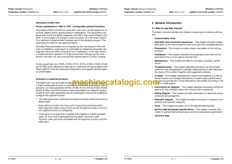
5. Parameters
5.1 General
5.2 General service parameters
5.3 Service parameters, travel functions
5.4 Service parameters, hydraulic functions
5.5 Factory parameters
6. Installation and commissioning
6.1 Transporting the truck
6.2 Transporting the mast
6.3 Safe lifting
6.4 Installing the battery
6.5 Using PIN codes
6.6 Programming PIN codes
6.7 Setting parameters
6.8 Function and safety checks
7. Maintenance
7.1 Introduction
7.2 Maintenance instructions
7.3 Maintenance schedule
8. Troubleshooting
8.1 General
8.2 Towing a defective truck
8.3 Emergency driving mode
8.4 Troubleshooting methods
8.5 Error code history
8.6 Error code system
8.7 Error codes
8.8 Troubleshooting chart
8.9 Built-in test function
8.10 Digital input/output status
8.11 Built-in test function for the tiller arm
8.12 Checking the built-in battery charger
9. Chassis 0000
9.1 General
9.2 Disassemble the drive unit from the fork frame
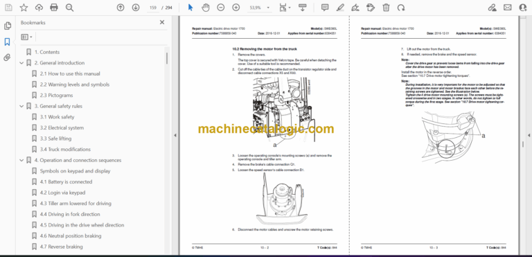
10. Electric drive motor 1700
10.1 Overview
10.2 Removing the motor from the truck
10.3 Removing the toothed wheel
10.4 Removing the motor bearings
10.5 Removing the RPM sensor
10.6 Installing the temperature sensor
10.7 Drive motor tightening torques
10.8 Cleaning
11. Drive gear 2550
11.1 General
11.2 Overview
11.3 Removing the drive gear from the truck
11.4 Fit grease nipples, steering bearing (Option)
11.5 Lubrication the steering bearings (Option)
11.6 Checking and changing the oil
11.7 Replacing the wheel hub seal
12. Brake system/Wheels C3000
12.1 Brake system – C3100
12.2 Parking brake 3180
12.3 Removing the parking brake
12.4 Fitting the parking brake
12.5 Checking the air gap
12.6 Drive wheel 3530
12.7 Castor wheels 3540
12.8 Spring replacement
12.9 Fork wheels 3550
13. Tiller arm 4000
13.1 Overview
13.2 Removing the tiller arm
13.3 Replacing the gas spring
13.4 Replacing the safety sensor
13.5 Electrical steering system – 4000
14. Electrical components-5000
14.1 Li-ion battery (Hoppecke)
14.2 Inspecting the battery
14.3 Replacing the wiring harness
14.4 Replacing the transistor regulator
15. Hydraulic system 6000
15.1 General
15.2 Hydraulic hygiene
15.3 Hydraulic unit 6100
15.4 Hydraulic connections 6230
15.5 Hose rupture valve
15.6 Hydraulic calibration
15.7 Adjusting the pressure limiting valve
15.8 Disassembling the hydraulic unit
15.9 Hydraulic unit tightening torques
16. Mast C7000
16.1 Main mast 7100
16.3 Main lift chain system 7120
16.4 Replacing the fork carriage
16.5 Replacing the cylinder
16.6 Replacement of the mast
17. Peripherals C8000
18. Accessories
18.1 Spider expansion unit
18.2 TLS – Truck log system
18.3 ID unit
18.4 I_Site
18.5 DC/DC converter
18.6 Collision sensor
18.7 Built-in battery charger
19. Instructions for disposal
19.1 General
19.2 Marking of plastics
19.3 Pressure vessels
19.4 Sorting categories
20. Electrical components and wiring diagrams
20.1 Electric components
20.2 Wiring diagram
21. Hydraulics chart
22. Tools
22.1 MQS contacts
22.2 AMP connectors
22.3 Molex connectors
22.4 Grease guns
22.5 Other tools
23. Oil and grease specification
23.1 General tightening torques
23.2 Oil and grease specification
24. Technical data
24.1 SWE080L
