Format: PDF (Printable Document)
File Language: English
File Pages: 210
File Size: 6.11 MB (Speed Download Link)
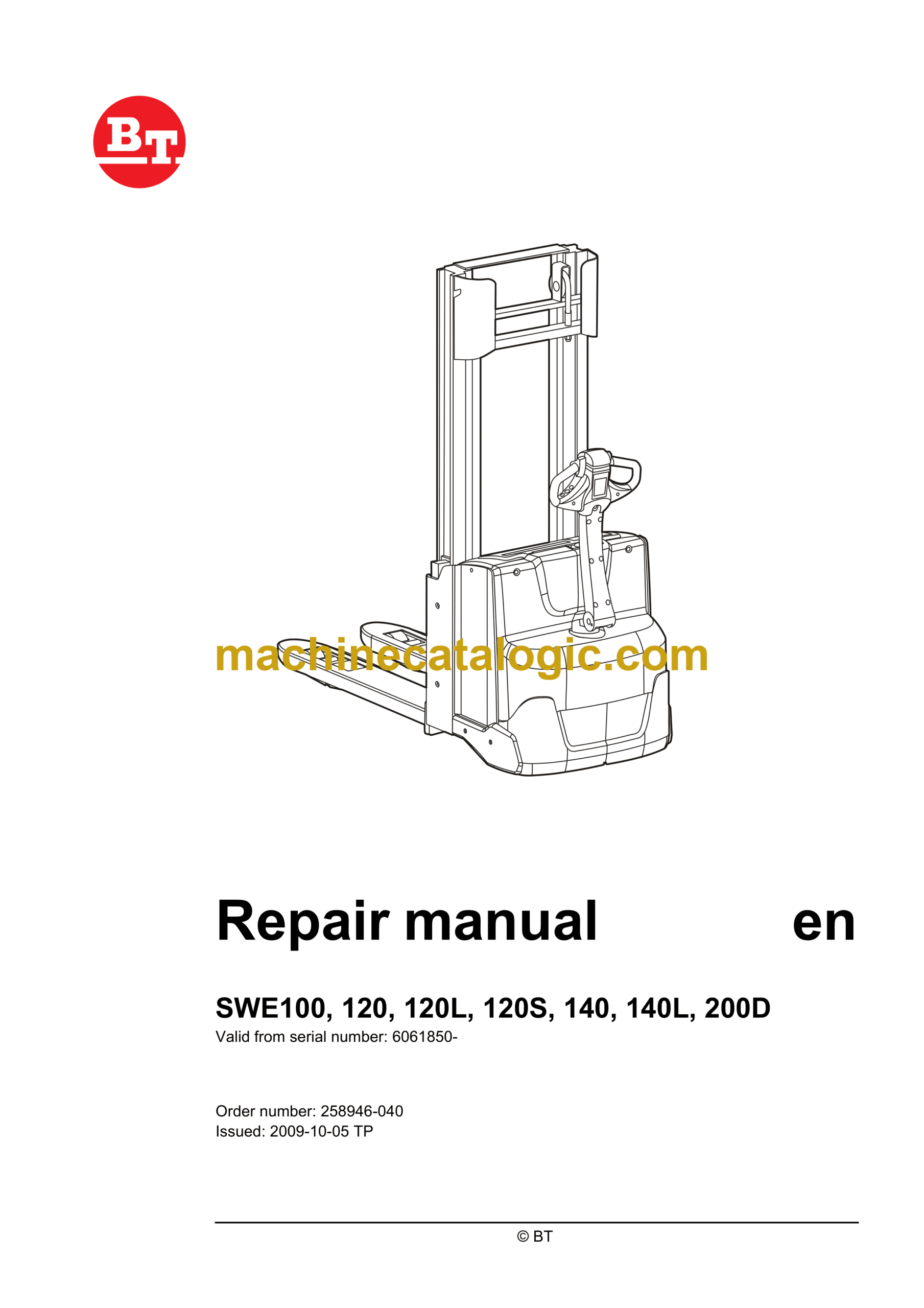
Brand: BT
Model: SWE100, SWE120, SWE120L, SWE120S, SWE140, SWE140L, SWE200D Electric Stacker
Part No: 6061850-
Type of Document: Repair Manual
$ 40
1 – Contents
2 – General introduction
2.1 How to use the manual
2.2 Warning symbols
2.3 Pictogram
3 – General safety rules
3.1 Safety while working
3.2 Electrical system
3.3 Safe lifting
4 – Installation
4.1 General
4.2 Battery installation
4.3 Programming PIN codes
4.4 Setting the parameters
4.5 Function and safety check
5 – Maintenance
5.1 General
5.2 Service intervals
5.3 Maintenance schedule
6 – Functions and parameters
6.1 General
6.2 Function description
6.3 Principle functions
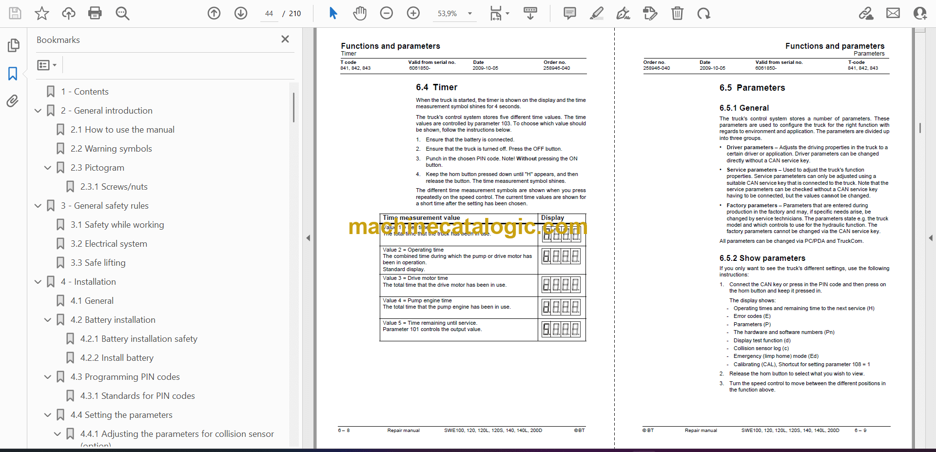
6.4 Timer
6.5 Parameters
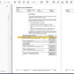
7 – Troubleshooting
7.1 General
Emergency travel mode
7.2 Troubleshooting methods
7.3 Error code history
7.4 Error code system
7.5 Error codes
7.6 Troubleshooting diagram.
7.7 Built-in test function
7.8 Status of digital inputs/outputs
7.9 Testing display function
8 – Chassis 0000
8.1 Support arm 0350
8.2 Motor fixing points 0450
8.3 Removing the platform
9 – Electrical drive motor 1700
9.1 Components
9.2 Disassemble engine and truck
9.3 Tightening torque Drive motor
9.4 Fitting the tempreature sensor
9.5 Cleaning
10 – Drive gear 2550
10.1 General
10.2 Components
10.3 Removing the gear from the truck (not applicable for SWE120S)
10.4 Removing the gear from the truck (not applicable for SWE120S)
11 – Brake 3180
11.1 Components
11.2 Release of brakes
12 – Drive wheel 3530
12.1 Changing drive wheel
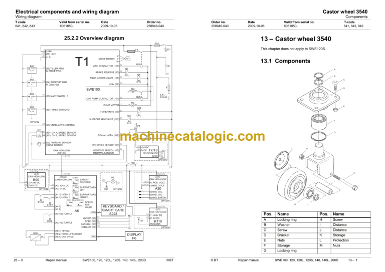
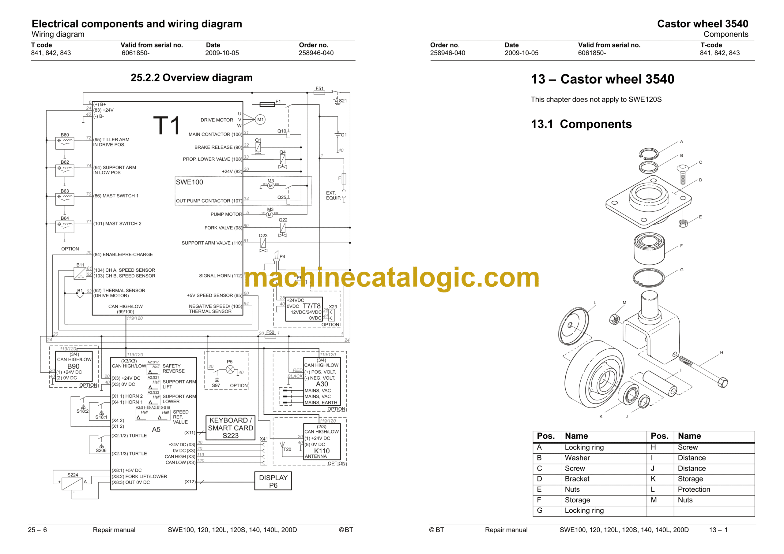
13 – Castor wheel 3540
13.1 Components
13.2 Changing castor wheel
14 – Support arm wheel 3550
15 – Tiller arm 4000
15.1 Components in tiller arm
15.2 Removing tiller arm
15.3 Changing gas spring
15.4 Changing the safety sensor
15.5 Components in tiller arm handle
16 – Electrical components
16.1 Changing wiring harness
16.2 Replacing the transistor regulator
17 – Hydraulic system 6000
17.1 General
17.2 Hygiene when working on hydraulics
17.3 Hydraulic unit 6100
17.4 Hydraulic connections 6230
17.5 Hydraulic calibration
17.6 Adjustment of the pressure limit valve
17.7 Disassembling the hydraulic unit
17.8 Hydraulic unit tightening torques
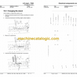
18 – Lift mast – 7000
18.1 Main mast 7100
18.2 Fork carriage 7420
18.3 Main lift chain system 7120
18.4 Changing the fork-lift trolley
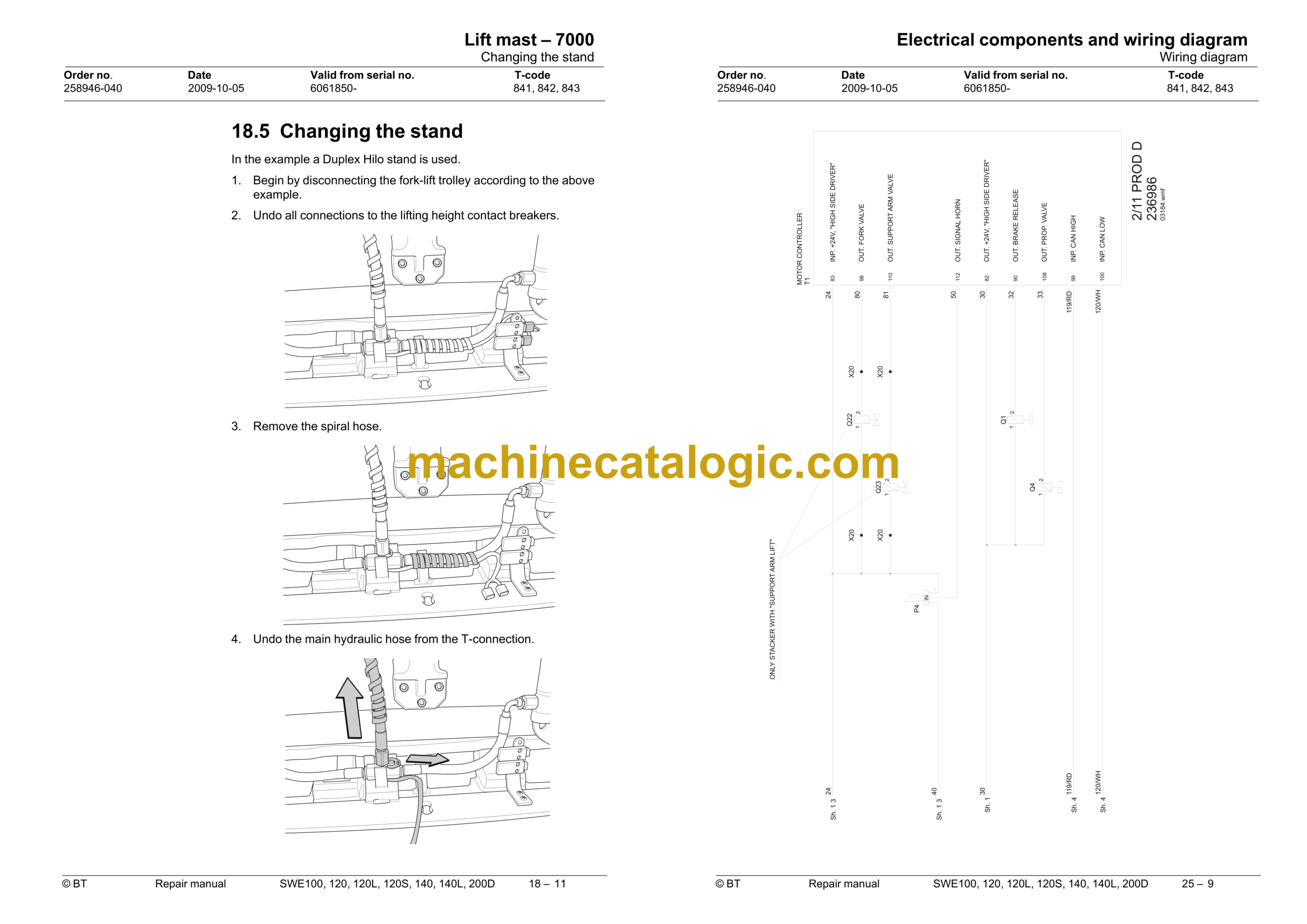
18.5 Changing the stand
19 – Accessories
19.1 Spider expansion unit
19.2 TLS – Truck log system
19.3 ID unit
19.4 Toyota Wireless Information System T.W.I.S.
19.5 Built-in battery charger
20 – Appendices
20.1 General
21 – Technical data
21.1 SWE100, SWE120, SWE140
21.2 SWE120L, SWE140L, SWE200D
21.3 SWE120S
21.4 Overflow pressure for the mast
22 – General tightening torque
22.1 General
22.2 Galvanised non-oiled bolts
22.3 Untreated, oiled bolts
23 – Tools
23.1 MQS contacts
23.2 AMP contacts
23.3 Molex contacts
23.4 Grease guns
23.5 Other tools
24 – Oil and grease specification
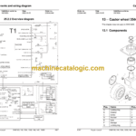
25 – Electrical components and wiring diagram
25.1 Electrical components
25.2 Wiring diagram
26 – Hydraulics chart
27 – Instructions for disposal
27.1 General
27.2 Marking of plastics
27.3 Pressure vessels
27.4 Sorting categories


