Format: PDF (Printable Document)
File Language: English
File Pages: 146
File Size: 6.56 MB (Speed Download Link)
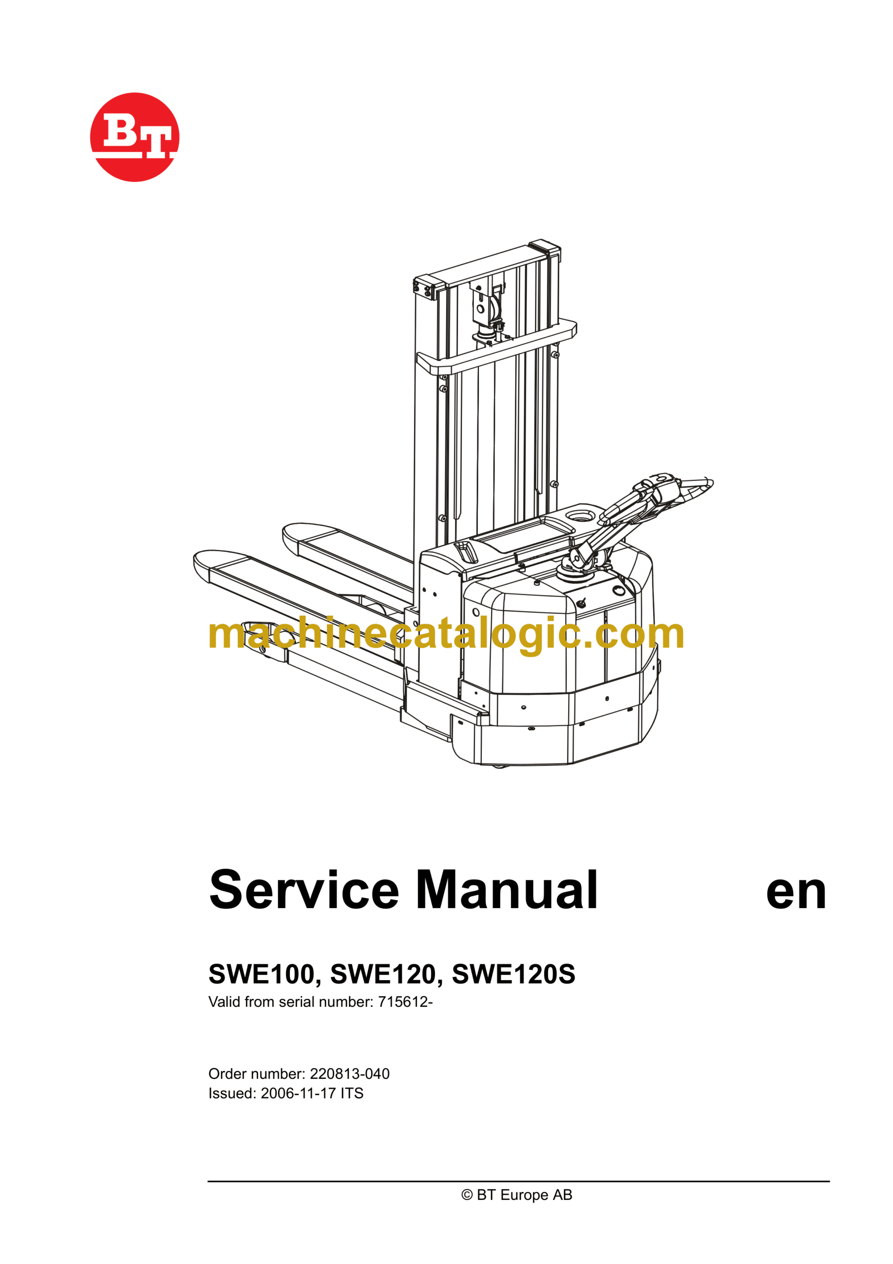
Brand: BT
Model: SWE100, SWE120, SWE120S Electric Stacker
Type of Document: Master Service Manual
$ 40
1- Table of contents
2- Technical data
2.1 General tightening torques
2.1.1 Galvanised, non-oiled bolts
2.1.2 Untreated, oiled bolts
3- Maintenance
3.1 Safety regulations with maintenance work
3.2 Cleaning and washing
3.2.1 External cleaning
3.2.2 Cleaning the motor compartment
3.2.3 Electrical components
3.3 Safe lifting
3.4 Maintenance Schedule
3.5 Lubrication schedule
3.6 Oil and grease specification
4- Tools
4.1 Super Seal connectors
4.2 AMP connectors
4.2.1 AMP Connectors, 040 series
4.3 Molex connectors
4.4 Grease guns
4.5 Other tools
5- Support arm chassis – 0350
5.1 General
5.2 Main components
5.3 Maintenance
5.4 Adjustment of the support arm width
5.5 Exchange of support arms
6- Electric drive motor – 1760
6.1 Component parts
6.1.1 Dismantling of motor from truck
6.1.2 Assembling
6.2 Service/Repairs
6.2.1 Dismantling of motor
6.2.2 Assembling of motor
6.2.3 Cleaning
6.3 Technical data
7- Drive unit/gear – 2550
7.1 General
7.2 Included components
7.3 Disassembly of the drive unit from the truck
7.4 Assembly of the drive unit in the truck
7.5 Oil inspection or changing oil
7.5.1 Oil inspection/replenishment
7.5.2 Changing oil
7.6 Replacing the gasket ring
7.6.1 Disassembly
7.6.2 Assembly
7.7 Leakage from top cover
8- Electro magnetic brake – 3370
8.1 Main components
8.1.1 Serial number 570989-
8.2 Maintenance
8.2.1 Exchange of brake disc
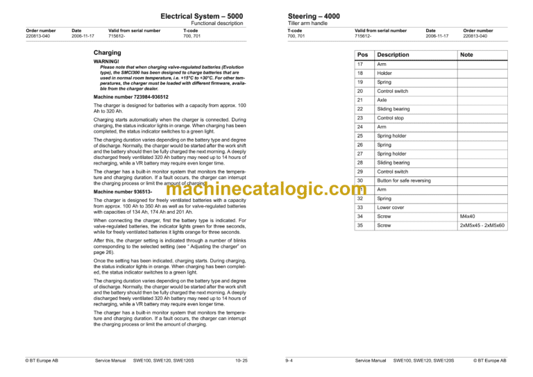
9- Steering – 4000
9.1 Component parts, tiller arm
9.2 Adjustments
9.2.1 Adjusting of brake microswitch
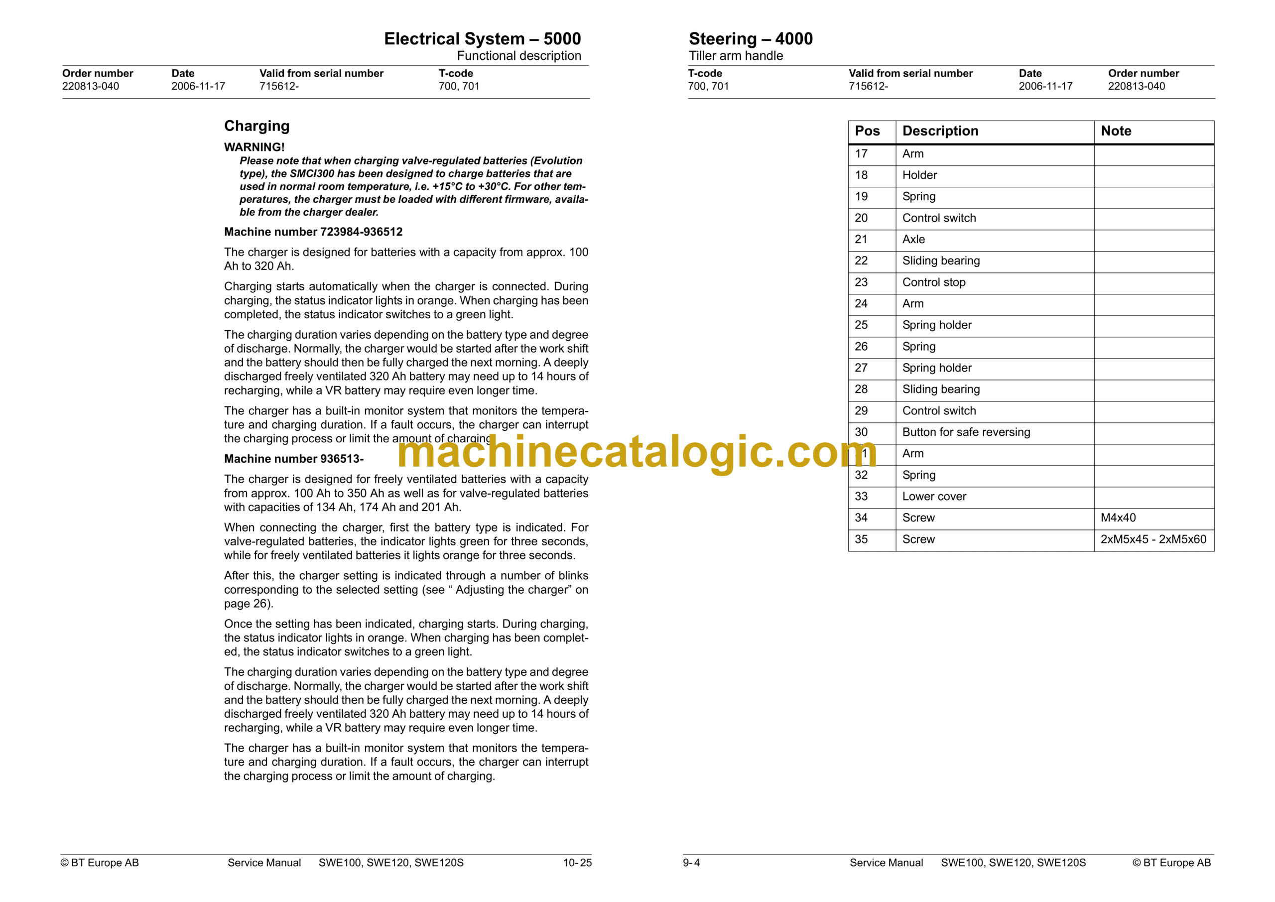
9.3 Tiller arm handle
9.3.1 Dismantling/Assembling
10- Electrical System – 5000
10.1 General
10.1.1 Software/hardware order numbers
10.1.2 Nomenclature
10.2 Electrical equipment overview
10.2.1 Electric component overview
10.3 Electrical wiring diagram
10.3.1 Symbol list
10.3.2 Overview
10.3.3 Detailed wiring diagram
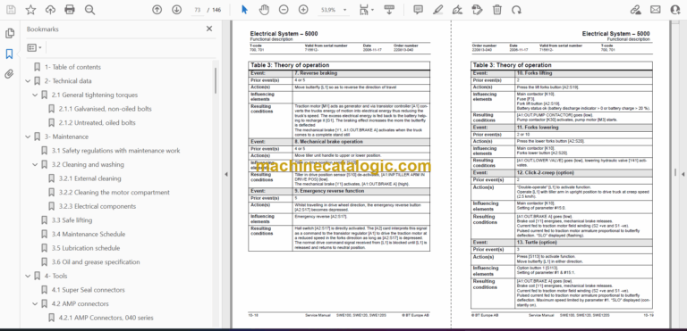
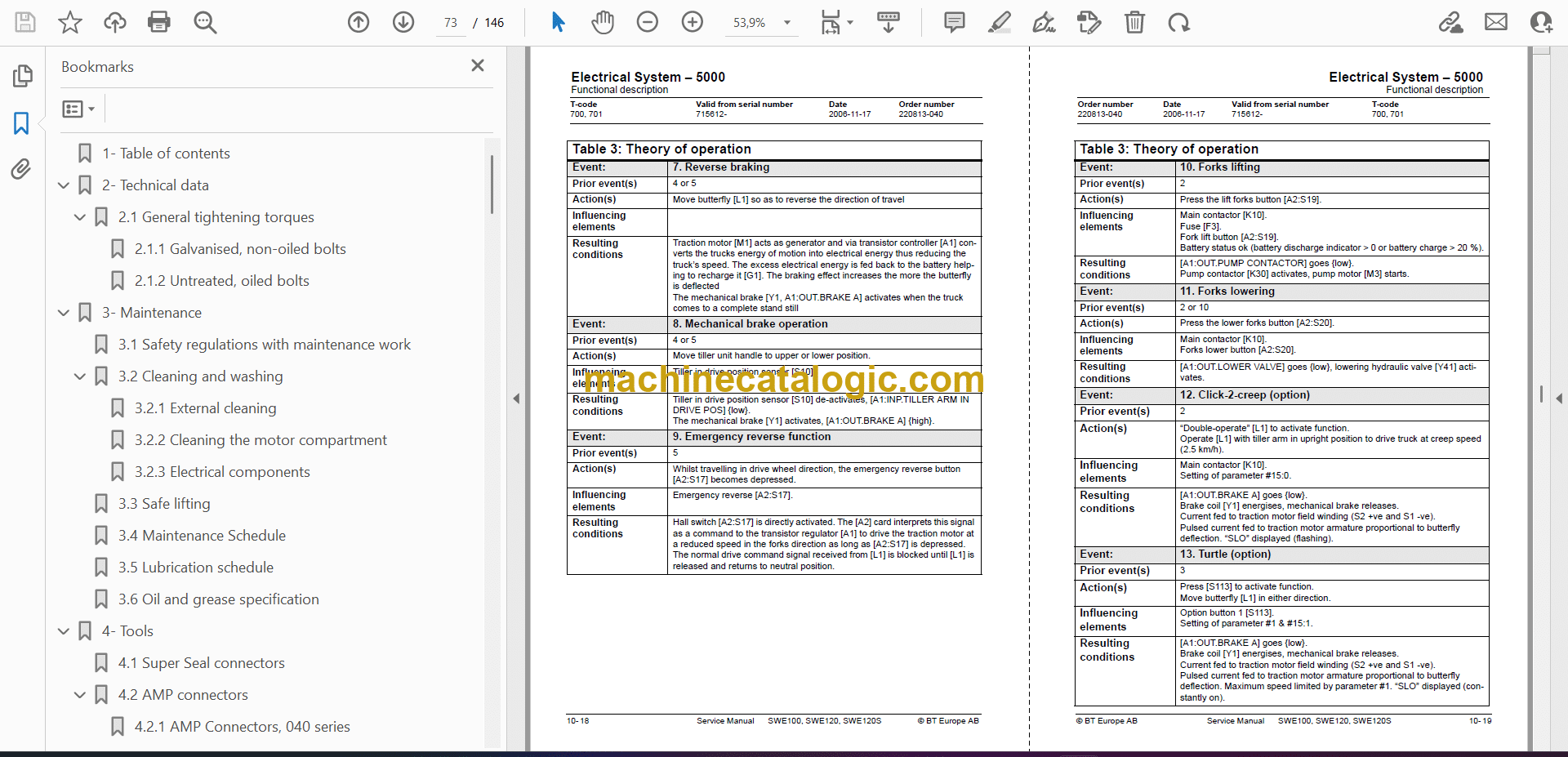
10.4 Functional description
10.4.1 Theory of operation
10.4.2 Spider expansion unit (SEU)
10.4.3 Hour meter and battery condition
10.4.4 TLS – Truck log system (optional)
10.4.5 ID unit (optional)
10.4.6 Built-in battery charger (optional)
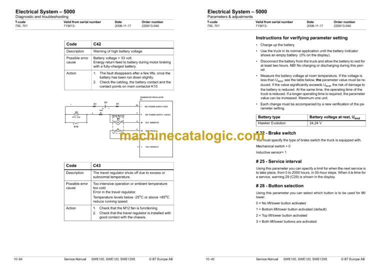
10.5 Parameters & adjustments
10.5.1 General
10.5.2 Displaying parameters – without the CAN service key
10.5.3 Adjusting operator parameters – without the CAN service key
10.5.4 Displaying & changing parameters – CAN service key connected
10.5.5 List of operator parameters
10.5.6 Description of operator parameters
10.5.7 List of Service parameters
10.5.8 Description of Service parameter
10.5.9 Configurable “Option” parameters
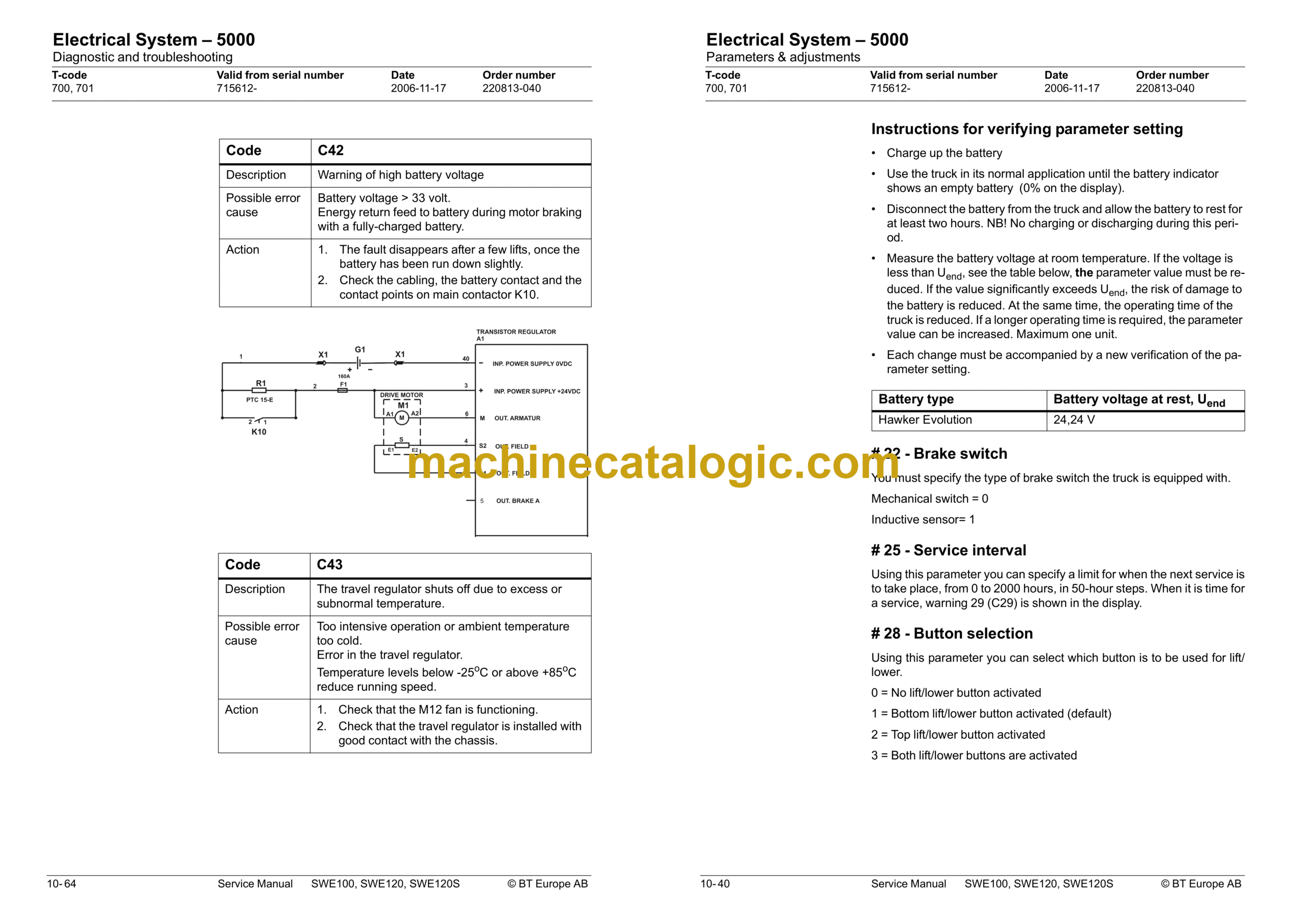
10.6 Diagnostic and troubleshooting
10.6.1 General
10.6.2 Fault code history
10.6.3 List of fault codes
10.6.4 Transistor regulator troubleshooting and error codes
10.6.5 Built-in Test Function
10.6.6 Display test mode
10.7 Technical specifications – Curtis 1243
11- Hydraulic system – 6000
11.1 General
11.2 Hydraulic diagram and components
11.2.1 Main components
11.2.2 Description
11.3 PowerTrak cylinder
11.3.1 Included components
11.3.2 Disassembling the PowerTrak cylinder and spring guides
12- Lifting Mast – 7000
12.1 Grease the beam flanges and beam ribs
12.2 Main lift chain system
12.2.1 General
12.2.2 Checking the chain setting
12.2.3 Chain inspection
12.2.4 Noise
12.2.5 Surface rust
12.2.6 Rusty links
12.2.7 Stiff links
12.2.8 Bolt rotation
12.2.9 Loose bolts
12.2.10 Outline wear
12.2.11 Stretching
12.2.12 Damage
12.2.13 Damaged discs
12.2.14 Damaged bolts
12.2.15 Dirty chain
12.3 Cleaning
12.4 Lubrication
