Format: PDF (Printable Document)
File Language: English
Brand: BT
Model: TE50, TE70 Tow Tractor
Type of Document: Maintenance, Operator and Parts Manual
$ 70
BT TE50, TE70 Tow Tractor Maintenance, Operator and Parts Manual
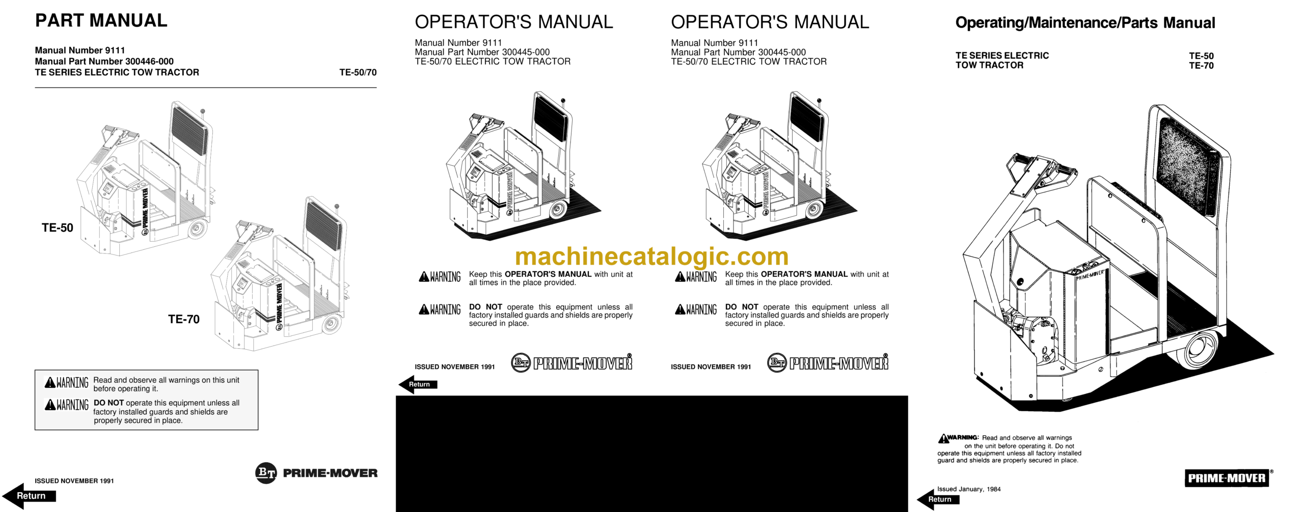
Front Cover
Parts Ordering Instructions
General Information
Alphabetical Index
Figure # 0.1 Decals and Parts List Assembly
Figure # 0.1 Parts List Index
Figure # 1.1 TE-50 Transmission and Handle Assembly
Figure # 1.2 TE-70 Transmission and Handle Assembly
Figure # 1.3 Handle Assembly
Figure # 1.4 TE-50 Transmission Assembly, Part # I
Figure # 1.5 TE-50 Transmission Assembly, Part # II
Figure # 1.6 TE-50 Drive Motor Assembly (Advanced 12 Volt 20190-01) (Prestolite 12 Volt 20190-00)
Figure # 1.7 TE-70 Transmission Assembly, Part # I
Figure # 1.8 TE-70 Transmission Assembly, Part II
Figure # 2.1 Resistor Master Control Switch (24121-01)
Figure # 2.2 Resistor 4 Speed Master Control Switch (24242-00)
Figure # 2.3 EV-100 SCR Master Control Switch (24455-02)
Figure # 2.4 TE-50 Resistor Electrical Schematic
Figure # 2.5 TE-50 Electrical Schematic Symbols
Figure # 2.6 TE-50 Two/Three Speed Control Wiring (12 Volt)
Figure # 2.7 TE-50 Two/Three Speed Power Component Wiring
Figure # 2.8 TE-50 Resistor Control Panel Assembly (12 Volt, 27259-08)
Figure # 2.9 TE-50 Two Speed Contactor Assembly (12 Volt, 27693-01)
Figure # 2.10 TE-50 Forward & Rearward Contactor Assembly (12 Volt, 27692-01)
Figure # 2.11 TE-50 Three Speed Contactor Panel Assembly (12 Volt, 27058-01)
Figure # 2.12 TE-50 Three Speed Contactor Assembly (12 Volt, 27158-00)
Figure # 2.13 TE-70 Resistor Electrical Schematic
Figure # 2.14 TE-70 Electrical Schematic Symbols
Figure # 2.15 TE-70 Three Speed Control Wiring (24 Volt)
Figure # 2.16 TE-70 Three Speed Power Wiring
Figure # 2.17 TE-70 Resistor Control Panel Assembly (24 Volt, 27259-09)
Figure # 2.18 TE-70 Two/Three Speed Contactor Assembly (24 Volt, 27693-00)
Figure # 2.19 TE-70 Forward & Rearward Contactor Assembly (24 Volt, 27692-00)
Figure # 2.20 TE-70 Three Speed Contactor Panel Assembly (24 Volt, 27266-00)
Figure # 2.21 TE-70 Fourth Speed Control Wiring (24 Volt)
Figure # 2.22 TE-70 Fourth Speed Power Component Wiring (24 Volt)
Figure # 2.23 TE-70 Fourth Speed Contactor Panel Assembly (27267-04)
Figure # 2.24 TE-70 Contactor Assembly (24 Volt, 27158-01)
Figure # 2.25 TE-70 EV-100 SCR Electrical Schematic
Figure # 2.26 TE-70 EV-100 SCR Electrical Schematic Symbols
Figure # 2.27 TE-70 EV-100 SCR Control Wiring
Figure # 2.28 TE-70 EV-100 SCR Two Speed Power Component Wiring
Figure # 2.29 TE-70 EV-100 SCR Contactor Panel Assembly (27707-00)
Figure # 2.30 TE-70 EV-100 Forward & Rearward Contactor Assembly (27692-00)
Figure # 2.31 TE-70 EV-100 Forward & Rearward Contactor Assembly (27693-02)
Figure # 2.32 TE-70 EV-100 SCR Panel Assembly
Figure # 2.33 TE-70 EV-100 SCR Control Panel (27691-01)
Figure # 2.34 Power Connector Assembly
Figure # 2.35 TE-50, 12 Volt Drive Motor Assembly (R90-4001, 300280-000, Advanced)
Figure # 2.36 TE-50, 12 Volt Drive Motor Assembly (MLD-4009, 20680-00, Prestolite)
Figure # 2.37 TE-70, 24 Volt Drive Motor Assembly (27895-00, 5BC48JB471) G.E.
Figure # 2.38 Wiring Assembly for Cold Storage
Figure # 4.1 Cushion and Floor Mat Installation
Figure # 4.2 Shielding Installation
Figure # 4.3 Frame Assembly
Figure # 4.4 Automatic Coupler and Tow Eye Assembly
Figure # 10.1 Special Tools and Lubrications
Numerical Index
Back Cover
Front Cover
Important Notice
Foreword
Table of Contents
Drive Safely
Introduction
Preliminary Service
Operator
Operating Practices
Data Plate and Decals
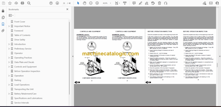
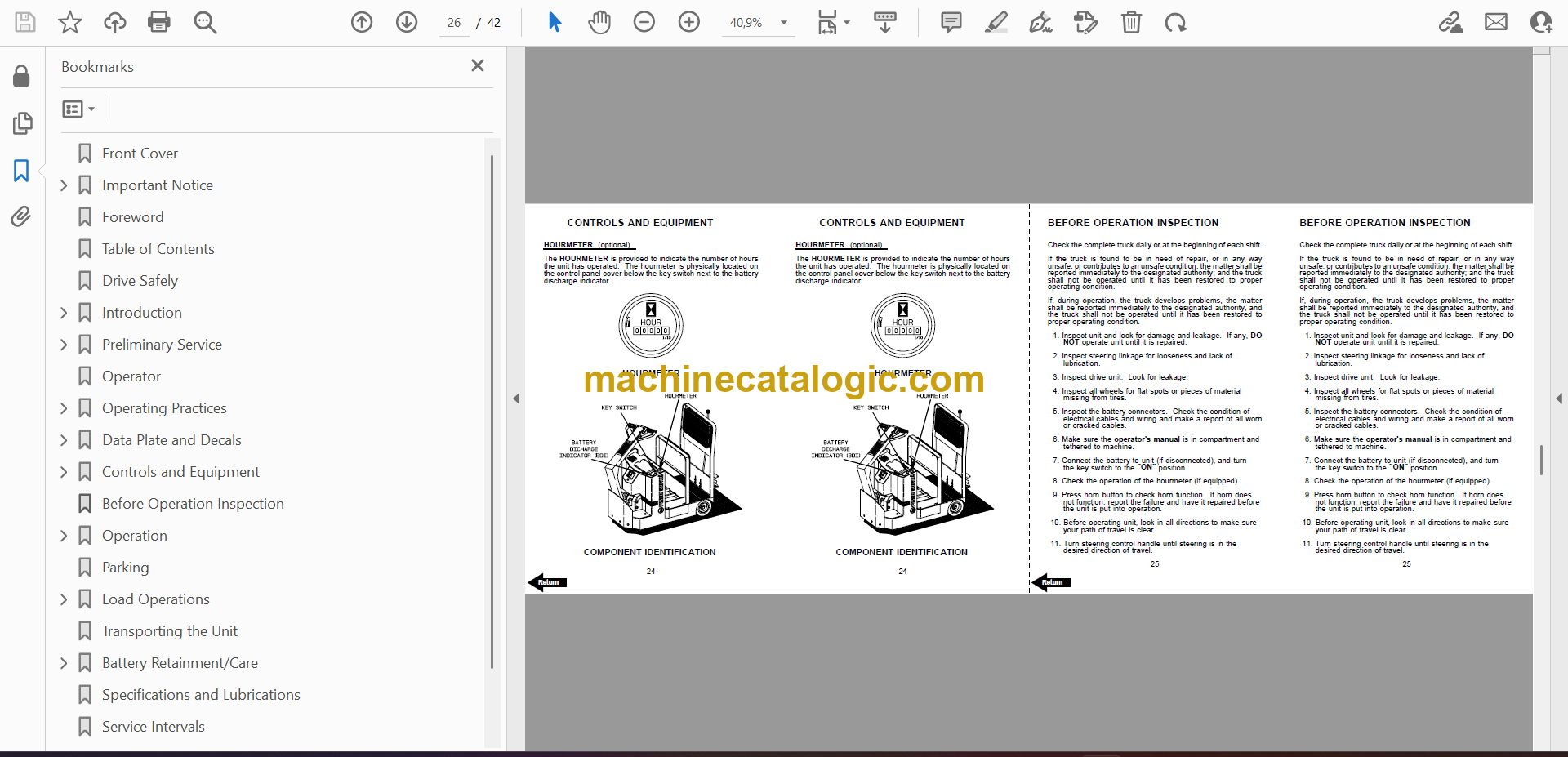
Controls and Equipment
Before Operation Inspection
Operation
Parking
Load Operations
Transporting the Unit
Battery Retainment/Care
Specifications and Lubrications
Service Intervals
Field Modifications
Back Cover
Front Cover
Warranty
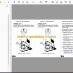
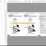
Operating Rules and Instructions
Maintenance Instructions
Parts Ordering Instructions
TE-50 and TE-70 Electric Tow Tractor Specifications
Figure # 1 Decal and Parts Assembly
Figure # 2 Parts List and Service Reference Index
Figure # 3 Shield Assembly
Figure # 4 TE-50 Transmission and Handle Assembly
Figure # 5 Handle Assembly
Figure # 6 Master Control Switch Assembly
Figure # 7 TE-50 22:1 Transmission Assembly
Figure # 8 TE-50 22:1 Drive Motor Assembly
Figure # 9 TE-50 22:1 Drive Motor, 12 Volt
Figure # 10 TE-70 Transmission and Handle Assembly
Figure # 11 TE-70 14:1 Transmission Assembly
Figure # 12 TE-70 14:1 Motor Assembly
Figure # 13 TE-50 Electrical Schematic
Figure # 14 Electrical Schematic
Figure # 15 Electrical Schematic Symbols
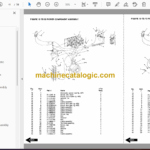
Figure # 16 Control Wiring Harness Assembly
Figure # 17 Dynamic Brake Wiring
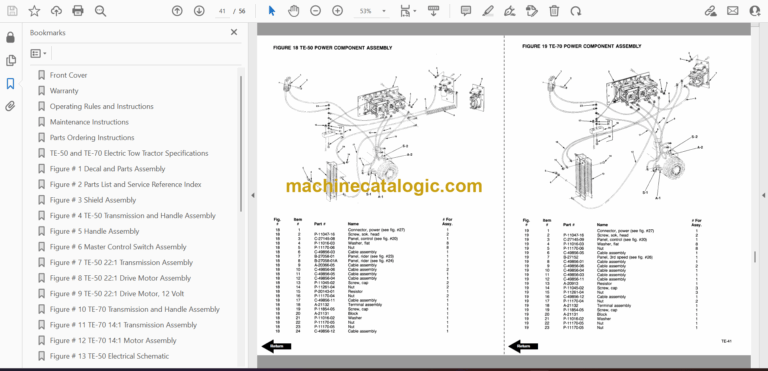
Figure # 18 TE-50 Power Component Assembly
Figure # 19 TE-70 Power Component Assembly
Figure # 20 Control Panel Assembly
Figure # 21 GE Contactor Assembly
Figure # 22 GE Contactor Assembly
Figure # 23 TE-50 3rd Speed Panel Assembly
Figure # 24 TE-50 Cableform 3rd Speed Panel Assembly
Figure # 25 Contactor Assembly
Figure # 26 TE-70 3rd Speed Panel Assembly
Figure # 27 Power Connector Assembly
Figure # 28 Foot Pedal Assembly
Figure # 29 Frame Assembly
Figure # 30 Spring Loaded Caster Assembly
Figure # 31 Automatic Coupler
Service Guide
Back Cover

