Format: PDF (Printable Document)
File Language: English
Brand: BT
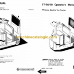
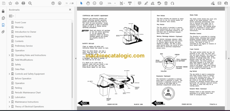
Model: TT50, TT70 Towing Tractor
Type of Document: Operator and Parts Manual
$ 70
BT TT50, TT70 Towing Tractor Operator and Parts Manual
Front Cover
Parts Ordering Instructions
General Information
Alphabetical Index
Figure # 0.1 Decals and Parts Assembly
Figure # 1.1 TT-50 22:1 Transmission and Handle Assembly
Figure # 1.2 TT-70 14:1 Transmission and Handle Assembly
Figure # 1.3 Tee Handle Assembly
Figure # 1.4 TT-50 22:1 Transmission Assembly, Part # I
Figure # 1.5 TT-50 22:1 Transmission Assembly, Part # II
Figure # 1.6 TT-50 22:1 Drive Motor Assembly
Figure # 1.7 TT-70 14:1 Transmission Assembly, Part # I
Figure # 1.8 TT-70 14:1 Transmission Assembly, Part II
Figure # 2.1 Resistor Master Control Switch
Figure # 2.2 Resistor 4 Speed Master Control Switch
Figure # 2.3 EV-100 SCR Master Control Switch
Figure # 2.4 TT-50 Resistor Electrical Schematic
Figure # 2.5 TT-50 Resistor Electrical Schematic Symbols
Figure # 2.6 TT-50 Two/Three Speed Control Wiring
Figure # 2.7 TT-50 Two/Three Speed Power Component Wiring
Figure # 2.8 TT-50 Resistor Control Panel Assembly, 12 Volt
Figure # 2.9 TT-50 Two Speed Contactor Assembly, 12 Volt
Figure # 2.10 TT-50 Forward & Rearward Contactor Assembly, 12 Volt
Figure # 2.11 TT-50 Three Speed Contactor Panel Assembly, 12 Volt
Figure # 2.12 TT-50 Three Speed Contactor Assembly, 12 Volt
Figure # 2.13 TT-70 Resistor Electrical Schematic
Figure # 2.14 TT-70 Resistor Electrical Schematic Symbols
Figure # 2.15 TE-70 Three Speed Control Wiring, 24 Volt
Figure # 2.16 TT-70 Three Speed Power Wiring
Figure # 2.17 TT-70 Resistor Control Panel Assembly, 24 Volt
Figure # 2.18 TT-70 Three Speed Contactor Assembly, 24 Volt
Figure # 2.19 TT-70 Forward & Rearward Contactor Assembly, 24 Volt
Figure # 2.20 TT-70 Three Speed Contactor Panel Assembly, 24 Volt
Figure # 2.21 TT-70 Fourth Speed Control Wiring, 24 Volt
Figure # 2.22 TT-70 Fourth Speed Power Component Wiring, 24 Volt
Figure # 2.23 TT-70 Fourth Speed Contactor Panel Assembly
Figure # 2.24 TT-70 Contactor Assembly, 24 Volt
Figure # 2.25 TT-70 EV-100 SCR Electrical Schematic
Figure # 2.26 TT-70 EV-100 SCR Electrical Schematic Symbols
Figure # 2.27 TT-70 EV-100 SCR Two/Three Speed Control Wiring
Figure # 2.28 TT-70 EV-100 SCR Two Speed Power Component Wiring
Figure # 2.29 TT-70 EV-100 SCR Contactor Panel Assembly
Figure # 2.30 TT-70 EV-100 SCR Forward & Rearward Contactor Assembly
Figure # 2.31 TT-70 EV-100 SCR 1A Contactor Assembly
Figure # 2.32 TT-70 EV-100 SCR Two Speed Panel Assembly
Figure # 2.33 TT-70 EV-100 SCR Three Speed Power Component Wiring
Figure # 2.34 TT-70 EV-100 SCR Three Speed Contactor Panel Assembly
Figure # 2.35 TT-70 EV-100 SCR Two/Three Speed Control Panel
Figure # 2.36 Resistor Power Connector Assembly
Figure # 2.37 TT-50 22:1 Two Speed (Only) Drive Motor Assembly, 12 Volt
Figure # 2.38 TT-50 22:1 Two or Three Speed Drive Motor Assembly, 12 Volt
Figure # 2.39 TT-70 14:1 Drive Motor Assembly, 24 Volt
Figure # 2.40 Wiring Assembly for Cold Storage
Figure # 4.1 Cushion and Floor Mat Installation
Figure # 4.2 Shielding Assembly
Figure # 4.3 Frame Assembly
Figure # 4.4 Automatic Coupler and Tow Eye Assembly
Figure # 7.1 Battery Travel Interrupt Installation
Figure # 10.1 Special Tools and Lubrications
Numerical Index
Back Cover
Front Cover
Warranty
Introduction to Owner
Important Notice
Contents
Preliminary Service
Operation
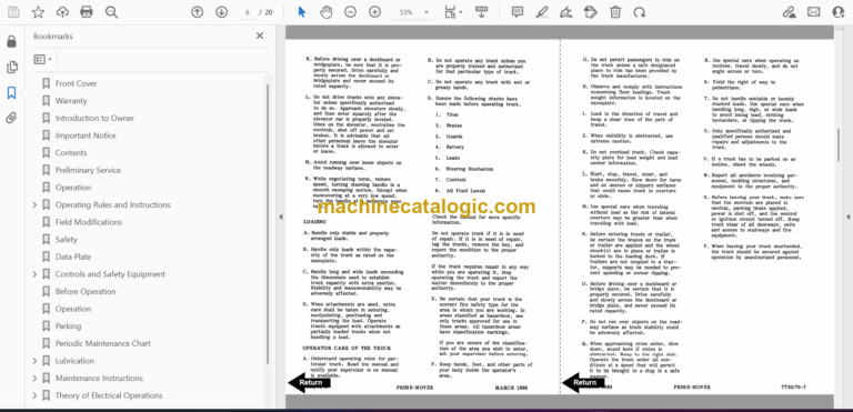
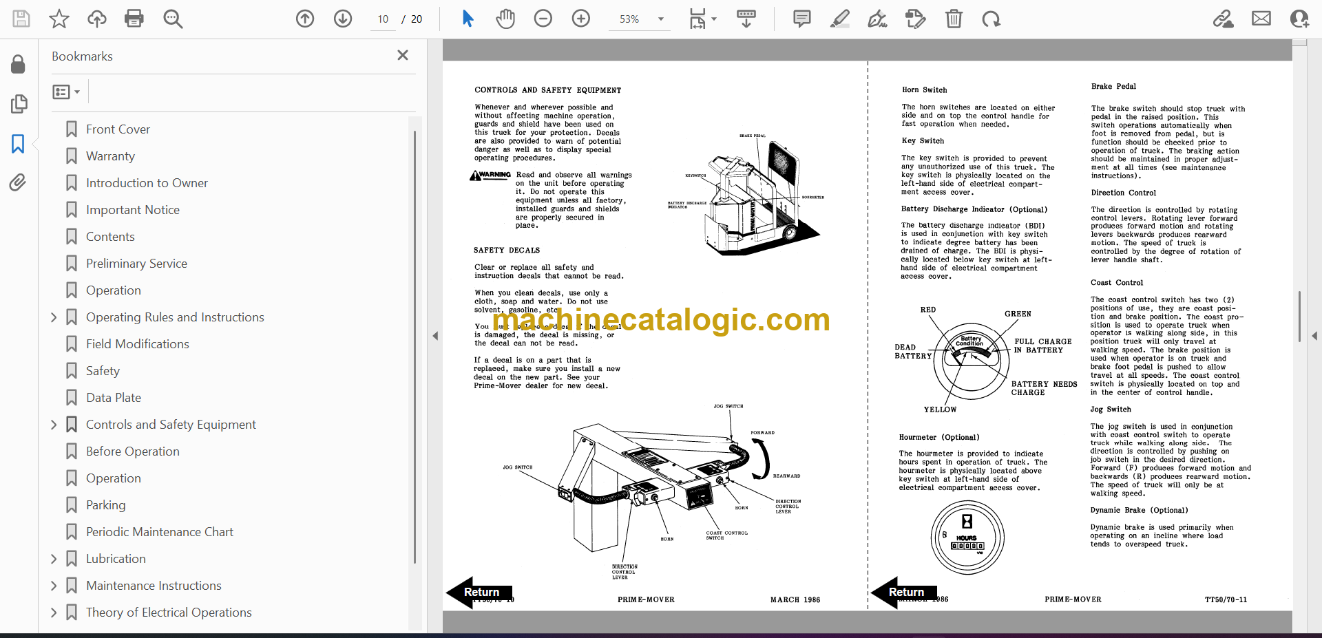
Operating Rules and Instructions
Field Modifications
Safety
Data Plate
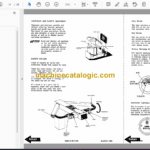
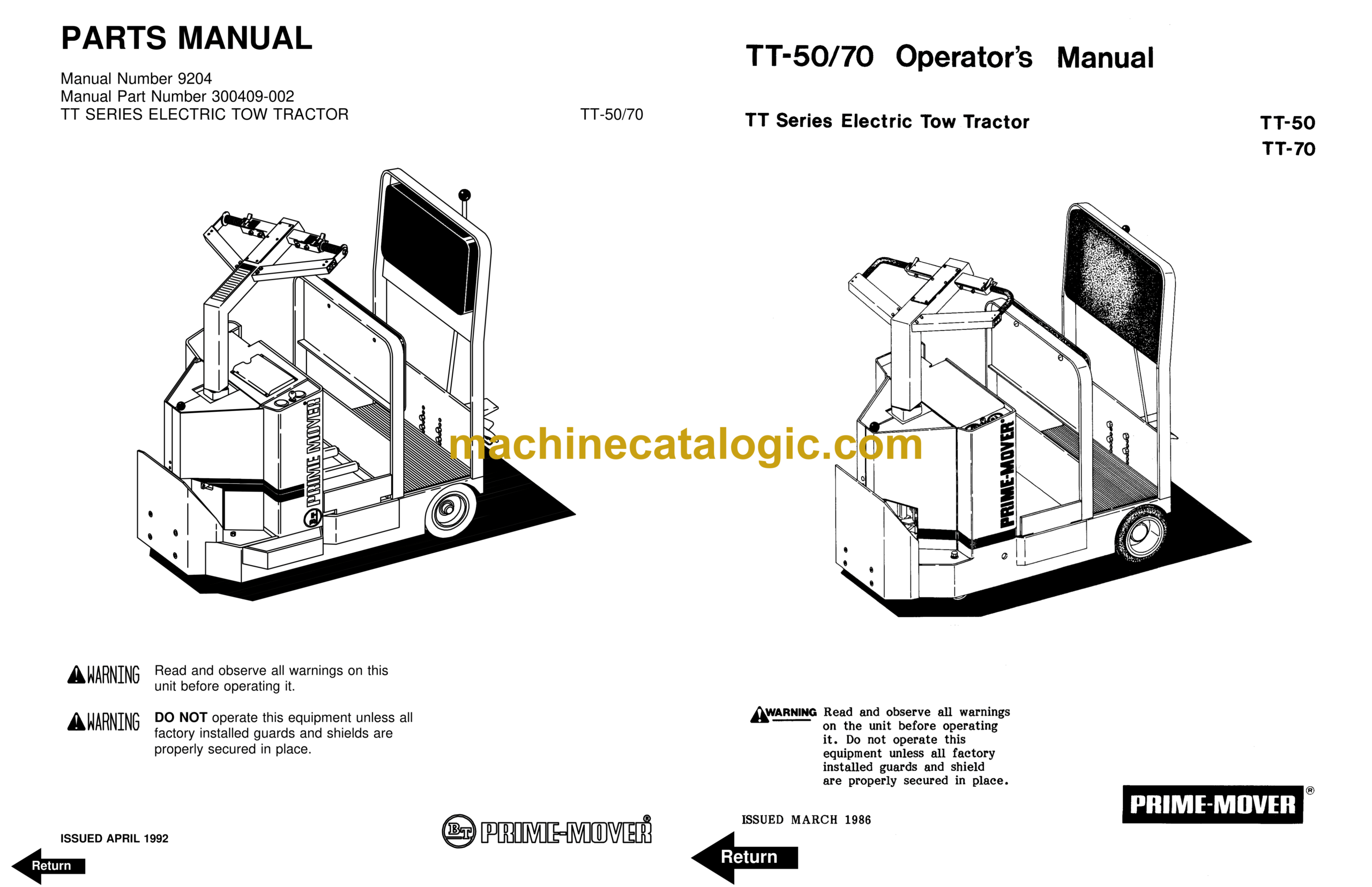
Controls and Safety Equipment
Before Operation
Operation
Parking
Periodic Maintenance Chart
Lubrication
Maintenance Instructions
Theory of Electrical Operations
Parts Ordering Instructions
Back Cover


