Format: PDF (Printable Document)
File Language: English
File Pages: 332
File Size: 5.76 MB (Speed Download Link)
Brand: BT
Model: VCE150A, 150AC, 125ASF, 125ACSF Electric Forklift
Type of Document: Master Service Manual
$ 40
19- Electrical system – 5000
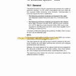
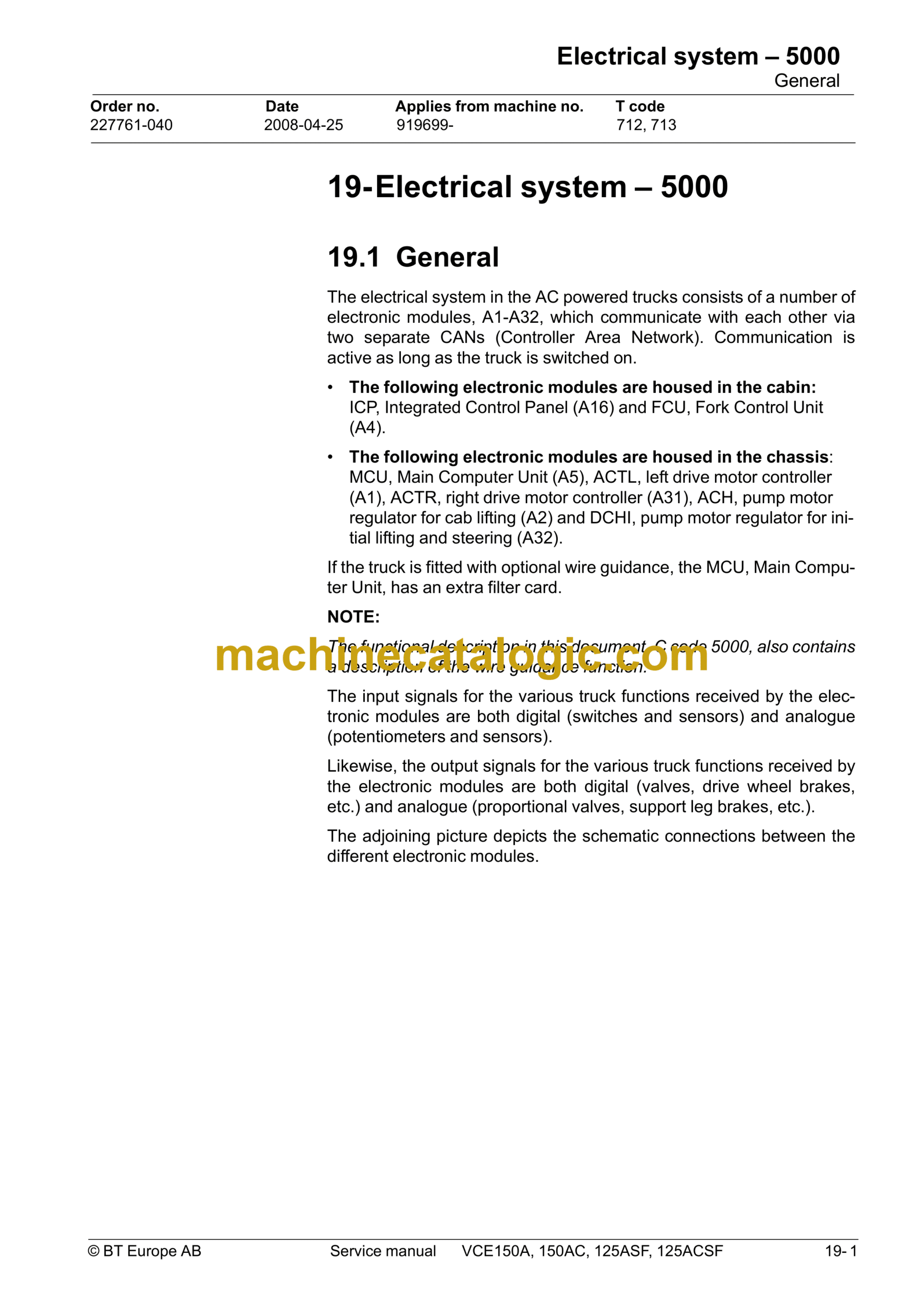
19.1 General
19.1.1 Terminology
19.1.2 Truck firmware
19.1.3 Communication
19.2 Main Computer Unit, MCU (A5)
19.2.1 General
19.2.2 Voltage feed
19.2.3 Battery negative
19.2.4 Electric connectors
19.2.5 Internal status monitoring
19.2.6 Resetting the battery indicator
19.2.7 External inputs and outputs
19.2.8 Installing a new card in the truck
19.2.9 Programming the MCU
19.3 Fork computer unit, FCU (A4)
19.3.1 General
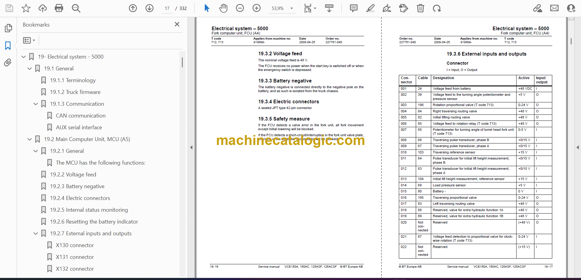
19.3.2 Voltage feed
19.3.3 Battery negative
19.3.4 Electric connectors
19.3.5 Safety measure
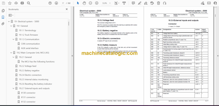
19.3.6 External inputs and outputs
19.3.7 Installing a new card in the truck
19.3.8 Programming
19.4 Integrated Control Panel, ICP (A16)
19.4.1 General
19.4.2 ICP modules
19.4.3 Voltage feed
19.4.4 Battery negative
19.4.5 External inputs and outputs
19.4.6 Installing a new ICP in the truck
19.4.7 Programming
19.5 AC regulators, ACTL (A1), ACTR (A31) and ACH (A2)
19.5.1 General
19.5.2 Connection terminal and terminal pillars
19.5.3 Technical data
19.5.4 Installing a new frequency converter in the truck
19.5.5 Programming
19.5.6 Maintenance
19.5.7 Safety
19.5.8 Cleaning
19.6 DC regulator, DCHI (A32)
19.6.1 General
19.6.2 Connection terminal and terminal pillars
19.6.3 Technical data
19.6.4 Installing a new transistor panel
19.7 Parameters
19.7.1 Diagnostics and troubleshooting
19.7.2 Maintenance
19.7.3 Safety
19.7.4 Cleaning
19.7.5 Hand-held terminal 1307
19.7.6 Using the hand-held terminal
19.7.7 Viewing and adjusting parameters
19.7.8 SPECIAL PROGRAM MODE
19.7.9 Using the TEST mode
19.7.10 Using the DIAGNOSTICS MODE
19.7.11 SPECIAL DIAGNOSTICS MODE
19.8 Electrical system, overview
T code 712
T code 713
19.9 List of symbols and electric circuit diagrams
19.9.1 List of symbols
19.9.2 Electrical wiring diagrams (T code 712)
19.9.3 Electrical wiring diagrams (T code 713)
19.10 Component List
19.10.1 Placement of components
19.10.2 Cabling contacts
19.11 Functional description, General
19.12 Functional description, starting, driving, steering and braking
19.12.1 Battery connected, truck switched off
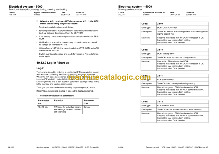
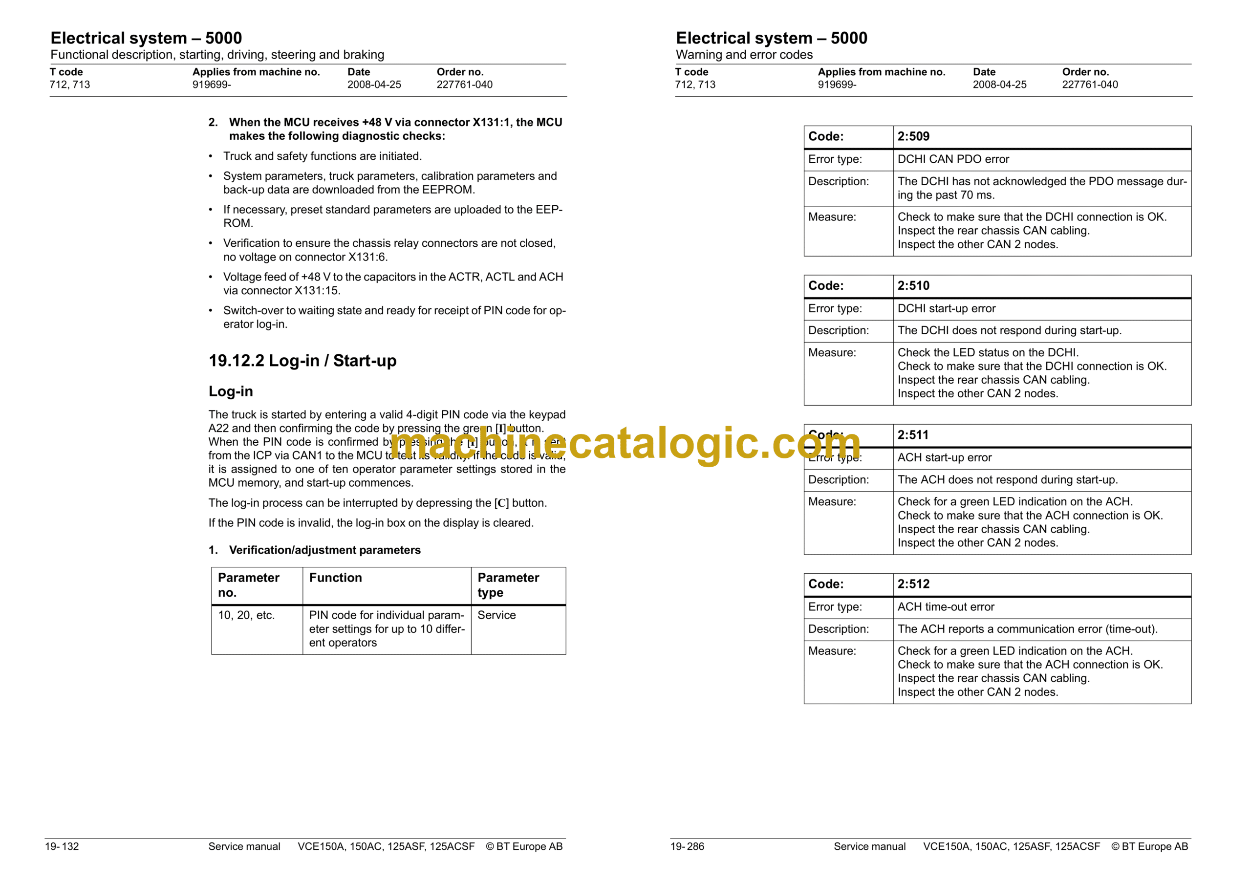
19.12.2 Log-in / Start-up
19.12.3 Log-out / Switch-off
19.12.4 Presence verification
19.12.5 Selecting the drive direction / Driving
19.12.6 Emergency driving mode
19.12.7 Travel speeds
19.12.8 Steering
19.12.9 Braking
19.13 Electrical description of the hydraulic functions
19.13.1 Allowed combined functions
19.13.2 Monitoring and functional limitations
19.13.3 Slack chain guard
19.13.4 Height measurement
19.13.5 Cabin lifting
19.13.6 Special height (lift limiter function)
19.13.7 Cabin lowering
19.13.8 Special function with cab lifting/ lowering and forks set straight ahead
19.14 Turret head unit (T code 712)
Safety monitoring
Automatic switching of the turret head fork unit’s functions
Fork lifting/lowering
Measuring the load weight
Side shifting/traversing of the forks
Fork rotation
19.14.1 Auto rotation
19.14.2 Miscellaneous electrical functions
19.14.3 Narrow aisle ID system
19.14.4 Alternative “narrow aisle system”
19.15 Shuttle fork unit (T code 713)
19.15.1 Traversing of the forks
19.15.2 Fork lifting/lowering
19.16 Wire guidance
19.16.1 General
19.16.2 Wire guidance components
19.16.3 Modified monitoring during wire guidance
19.16.4 Functional description
19.17 Display
19.17.1 Normal mode
19.17.2 Information mode
19.18 Calibration Turret Head (T code 712)
19.18.1 Calibration mode
19.19 Calibration Shuttle fork (T code 713)
19.19.1 Calibration of Shuttle fork
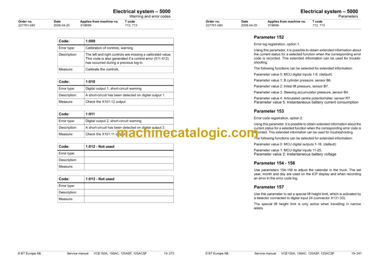
19.20 Parameters
19.20.1 Accessing parameters
19.20.2 Operator parameters (operators 1-10)
19.20.3 Truck parameters
19.20.4 MCU parameters
19.20.5 Wire guidance parameters:
19.20.6 FCU parameters (T code 712)
19.21 Parameters Shuttle fork (T code 713)
19.21.1 Service Parameters (T code 713)
19.21.2 Learned data (T code 713)
19.21.3 ICP parameters
19.22 Warning and error codes
19.22.1 Error handling
19.22.2 Safety logics
19.23 Warning and error codes
19.23.1 ICP, code group 1
19.23.2 MCU, code group 2
19.23.3 Drive system, code group 3
19.23.4 Cabin lift system, code group 4
19.23.5 Steering system, code group 5
19.23.6 Initial lift and turret head fork unit systems, code group 6 (T code 712)
19.23.7 Shuttle fork system (including FCU warnings) – code group 6 (T code 713)
