Format: PDF (Printable Document)
File Language: English
File Pages: 686
File Size: 19.23 MB (Speed Download Link)
Brand: BT
Model: Veflex VR, VR SF, VRE150, VRE125SF
Part No: 6004330–
Type of Document: Master Service Manual
$ 40
1- Technical data
2- Maintenance
2.1 Introduction and safety, maintenance
2.2 Safety regulations during maintenance work
2.3 Cleaning and washing
2.4 Safe lifting
2.5 Maintenance chart
2.6 Oil and grease specifications
3- Tools
3.1 Electrical contacts
3.2 Other tools
4- Chassis – 0000
4.1 General
4.2 List of tools
4.3 Transporting the truck
4.4 Assembling the mast
4.5 Installation in narrow aisles
5- Frame, mounted components – 0400
5.1 General tightening torque
6- Driver Protection – 0840
6.1 General
6.2 Tilt Stops
7- Electric Pump Motor – 1710
7.1 General
7.2 Dismantling the Pump Motor
7.3 Removing and Replacing the Pump Motor
7.4 Bearing Replacement
7.5 Installation Instructions for External Temperature Sensor
8- Electric Steering Motor – 1730
8.1 General
8.2 Replacing the Steering Motor
8.3 Removing and Replacing the Carbon Brushes
9- Electric Drive Motor – 1760
9.1 General
9.2 Dismantling the Drive Motor
9.3 Dismantling and Assembling the Drive Motor
9.4 Bearing Replacement
9.2 Installation Instructions for External Temperature Sensor
10- Mechanical Drive Gear Unit – 2550
10.1 General
10.2 Drive/Transmission Assembly’s Main Components and Technical Data
10.3 Replacing the Drive Motor/Drive Transmission
10.4 Checking/Replacing the Oil
10.2 Repairs
11- Travel brake system – 3100
11.1 Brake system
11.2 Description of function
11.3 Electromechanical disc brake, drive motor
11.4 Disassembly
11.5 Inspection
11.6 Assembly
11.7 Maintenance
11.8 Multiple disc brake, support arm
12- Drive wheel – 3530
12.1 General
12.2 Dismantling the drive wheel
12.3 Assembling the drive wheel
13- Fork/support arm wheel – 3550
13.1 General
13.2 Dismantling the wheel
13.3 Assembling the wheel
13.4 Dismantling/assembling the wheel bearings
14- Electric steering wheel/lever – 4310
14.1 General
14.2 Replacement of the steering generator
15- Steering angle sensor – 4350
15.1 General
15.2 Procedure
16- Automatic steering system – 4500
16.1 General
16.2 Generator
16.3 Wire guidance system overview
16.4 Wire guidance components
16.5 Operating description
16.6 Error Codes
17- Electrical System – 5000.1
17.1 General
17.2 Electronics Card, traction controller A1 and lift controller A2
17.3 Electronics Card, Fork Apparatus, A4
17.2 Electronics Card, Main Card, A5
17.3 Electrical System, Overview
17.4 Symbol List and Wiring Diagrams
17.2 Functional Description
17.3 Parameter
17.2 Instrument Panel and Display
17.3 Codes
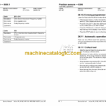
18- Electrical system – 5000.2
18.1 General
18.2 Logic card, drive controller A1 and lift controller A2
18.3 Logic card, fork unit, A4
18.4 Logic card, main card, A5
18.5 Electric system, overview
18.6 Symbol list and wiring diagrams
18.7 Function description
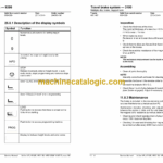
18.8 Display and programming
18.9 Setting all parameters
18.10 Warning codes
18.11 Error codes
18.12 Truck log system, code lock
18.13 I/O module
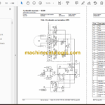
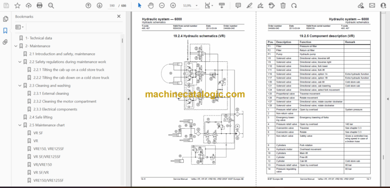
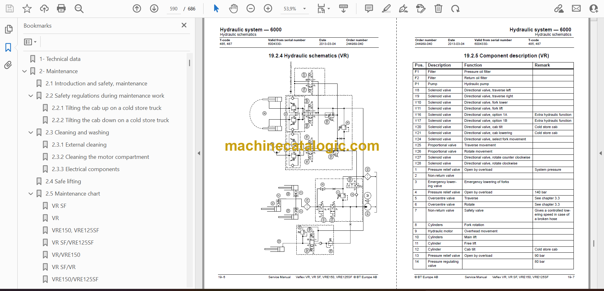
19- Hydraulic system – 6000
19.1 General
19.2 Hydraulic schematics
19.3 Hydraulic components, positioning
20- Hydraulic pump – 6140
20.1 General
20.2 Replacing the hydraulic pump
21- Hydraulic connections – 6230
21.1 General
21.2 Tightening torque for hydraulic connections
21.3 Quick connection
22- Main lift chain system – 7120
22.1 General
22.2 Checking the chain setting
22.3 Chain inspection
22.4 Cleaning
22.5 Lubrication
23- Turret Head Fork Apparatus – 7700 (VR, VRE150)
23.1 General description
23.2 Inspection and maintenance
23.3 Adjustment of turret head fork apparatus
23.4 Replacing components
24- Shuttle fork unit – 7800 (VR SF, VRE125SF)
24.1 Maintenance
24.2 Replacement of shuttle fork unit
25- Charger BTCM – 8340
25.1 General
25.2 Installation
25.3 Function and use
25.4 Display and keyboard
25.2 Service and maintenance
25.2 Trouble shooting
25.2 Service actions
25.2 Preventive maintenance
26- Position sensors – 9390
26.1 Height Indication and Height Pre- Set
26.2 Components for Height Indication/ Height Pre-Set
26.3 Height Indication
26.4 Height Indication
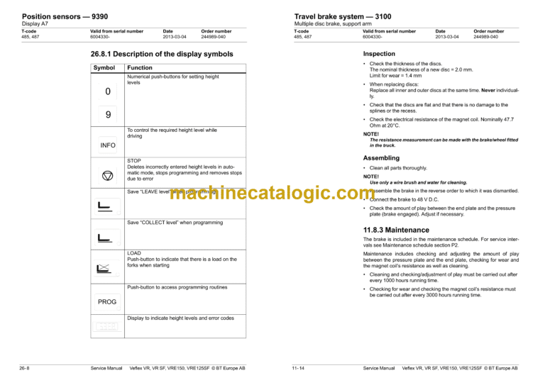
26.5 Display A8
26.6 Height Pre-Set
26.7 Function
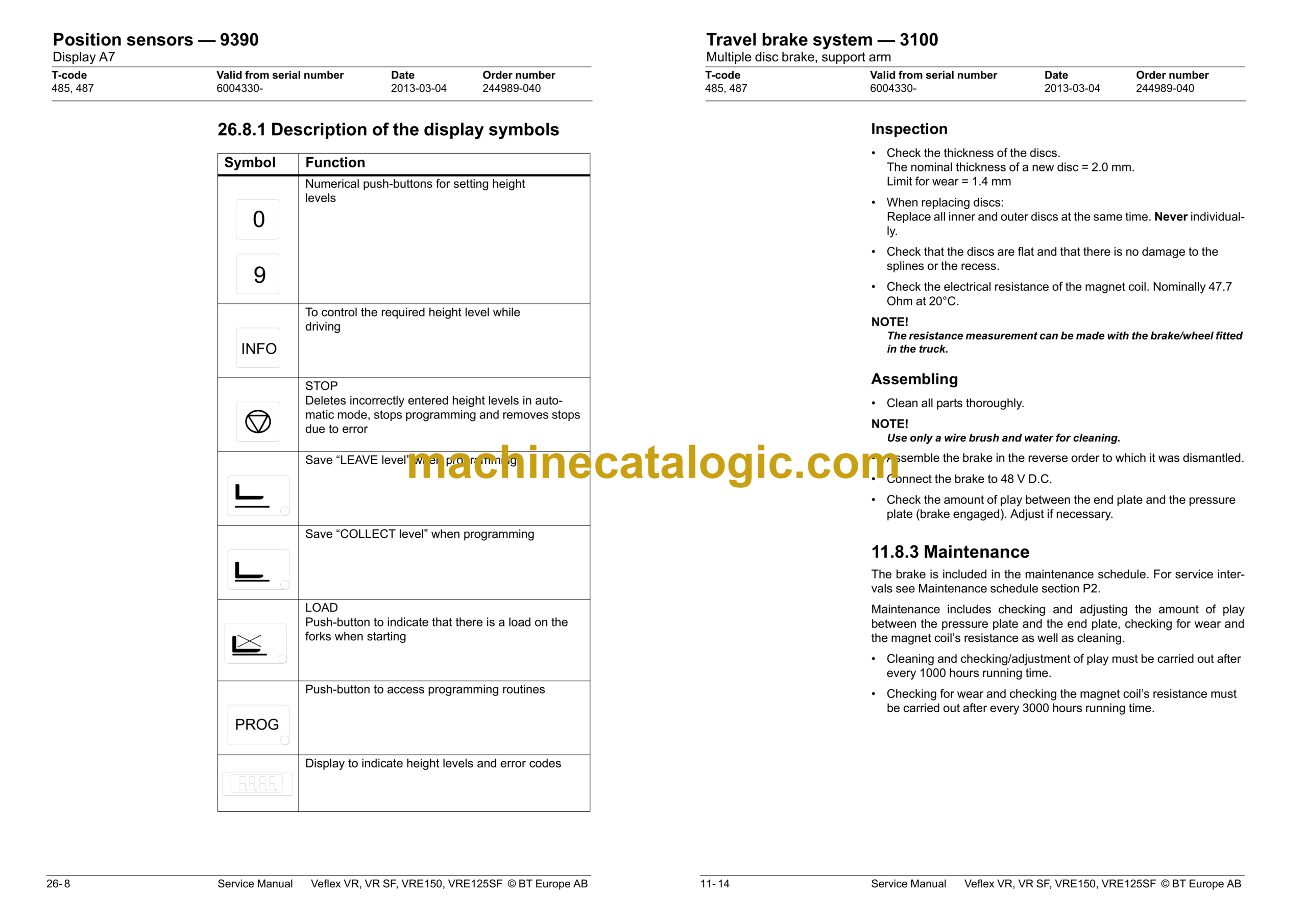
26.8 Display A7
26.9 Assembly of height preset
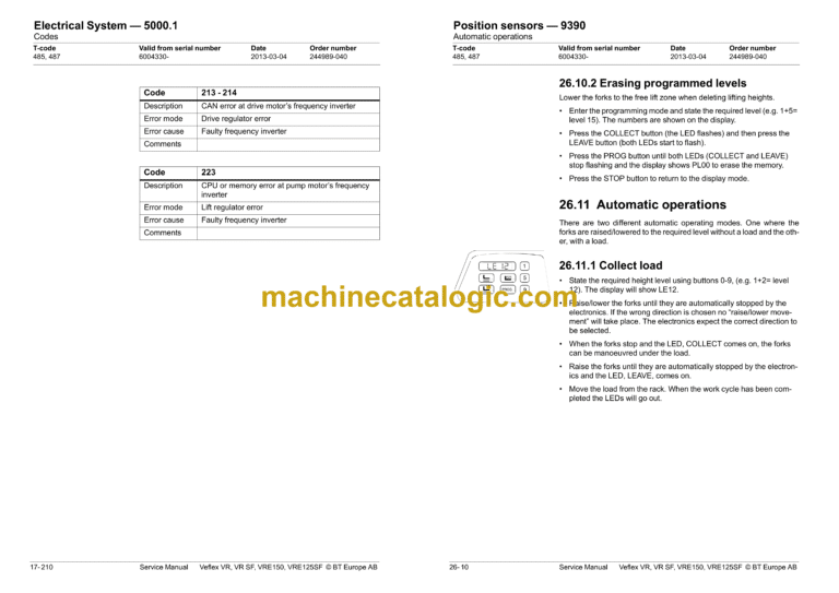
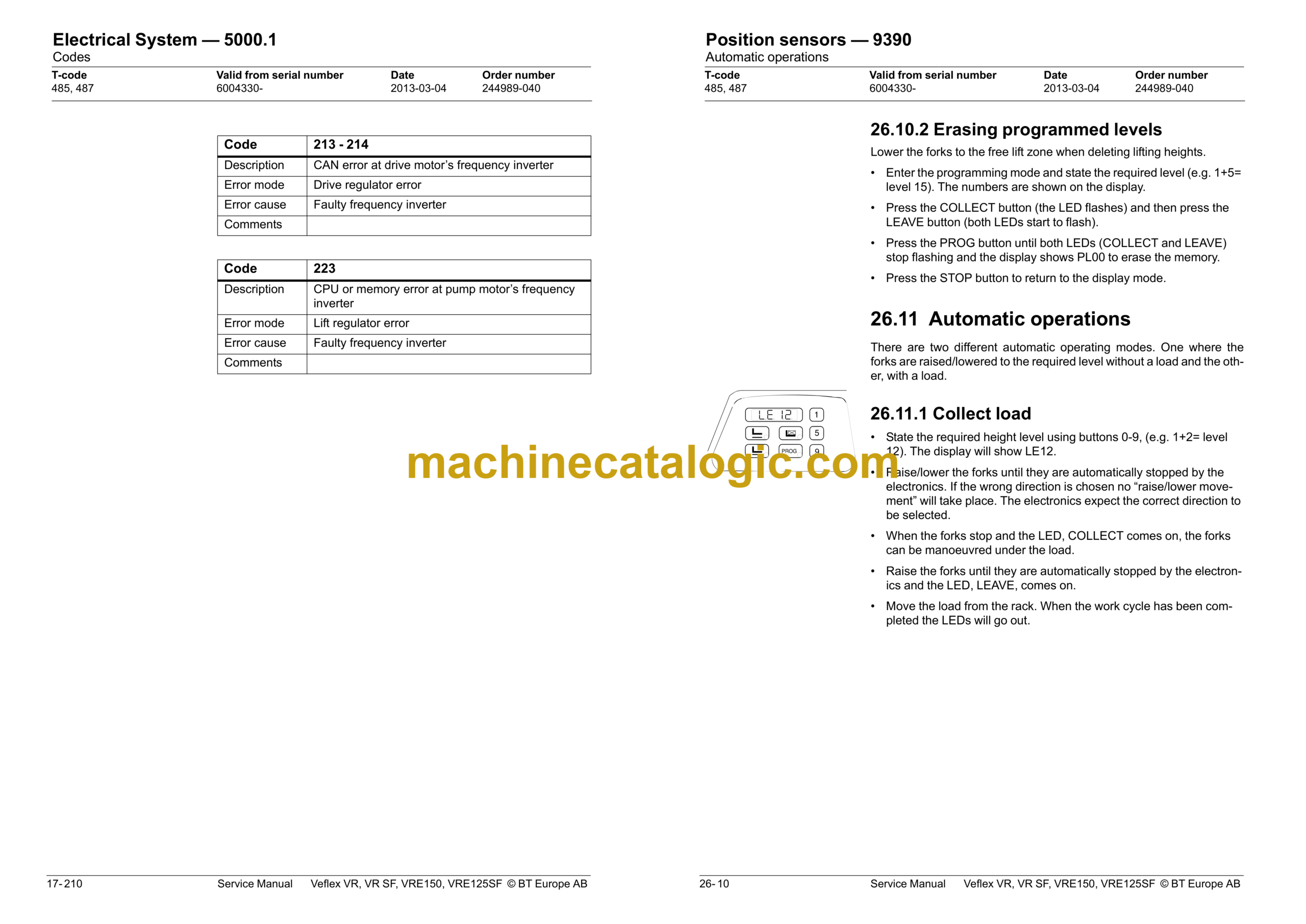
26.10 Programming
26.11 Automatic operations
26.12 Parameters
26.13 Programming parameters
26.14 Error codes
