Format: PDF (Printable Document)
File Language: English
File Pages: 146
File Size: 13.05 MB (Speed Download Link)
Brand: Bucyrus
Model: SCH5000 Hydraulic Track Drill
Book No: 343654
Type of Document: Operator and Maintenance Manual
$ 50
The Bucyrus SCH5000 Track Drill is designed to push through demanding drilling environments where torque, stability, and consistent penetration matter. This Operator and Maintenance Manual explains drilling techniques, rotary drive behavior, feed system control, hydraulic pressure management, and cooling system upkeep. It gives crews the tools to keep penetration rates consistent while avoiding overheating and mechanical stress.
Applications & Use Cases
Daily drilling procedures for varying ground hardness
Maintaining rotary drive and spindle components
Diagnosing feed motor hesitation or power loss
Monitoring cooling system performance under heavy use
Ensuring proper lubrication for extended drilling campaigns
FAQ
Does it include operator guidance?
Yes. It covers drilling technique, safe operation, and machine response.
Is maintenance explained for field conditions?
Absolutely. It supports real mining workflows.
Safety Note
Depressurize hydraulic circuits and secure the drill mast before any service work.
SECTION 1 SAFETY
Overview of Potential Hazards …………………………………………………………………………………. 1-2
Before Operation ………………………………………………………………………………………………….. 1-3
Clearance from High Voltage Lines …………………………………………………………………………… 1-3
Operation and After Operation …………………………………………………………………………………. 1-4
Maintenance and Equipment Transfer ………………………………………………………………………… 1-5
Stability Limits ……………………………………………………………………………………………………… 1-6
SECTION 2 OPERATOR CONTROLS
Tram / Drill Positioning Controls………………………………………………………………………………. 2-2
Instrument Panel – Non-Cab with 3306 Engine ……………………………………………………………… 2-4
Instrument Panel – Non-Cab with C11 Engine ……………………………………………………………….. 2-6
Drilling Controls – Non-Cab Machine …………………………………………………………………………… 2-8
Instrument Panel – Cab Machine ……………………………………………………………………………… 2-12
Drilling Controls – Cab Machine ………………………………………………………………………………. 2-14
Tramming Controls – Cab Machine ………………………………………………………………………….. 2-16
Drill Positioning Controls – Cab Machine …………………………………………………………………… 2-18
Air Ride Seat Adjustment ………………………………………………………………………………………. 2-20
SECTION 3 OPERATING PROCEDURES
Personal Safety ……………………………………………………………………………………………………. 3-2
Walk-Around Checks ……………………………………………………………………………………………… 3-3
Pre-Start Checklist ………………………………………………………………………………………………… 3-4
Engine and Gearcases ………………………………………………………………………………………….. 3-5
Pneumatic System ………………………………………………………………………………………………. 3-5
Feed Table Pivot Pin …………………………………………………………………………………………….. 3-6
Weekly Checks……………………………………………………………………………………………………. 3-6
Boom, Feed and Drill ……………………………………………………………………………………………. 3-7
Drill Accumulators ……………………………………………………………………………………………….. 3-7
Daily Maintenance Checklist …………………………………………………………………………………….. 3-8
Mounting & Dismounting Machine …………………………………………………………………………….. 3-9
Start-Up Procedure ……………………………………………………………………………………………… 3-10
Cold Weather Starting ………………………………………………………………………………………… 3-11
Tramming-Preliminary Checks and Warnings ……………………………………………………………… 3-12
Tramming from Operator’s Cab ……………………………………………………………………………… 3-13
Tramming from Tram Station ………………………………………………………………………………… 3-14
Shutdown Procedure……………………………………………………………………………………………. 3-16
SECTION 4 DRILLING PROCEDURES
Loading Drill Steel …………………………………………………………………………………………………. 4-2
Drill Positioning Procedure ……………………………………………………………………………………… 4-4
Position Feed for Vertical Drilling …………………………………………………………………………….. 4-6
Vertical Indicator (optional) …………………………………………………………………………………….. 4-6
Position Feed for Angle Drilling ………………………………………………………………………………. 4-7
Repositioning Feed or Lowering Feed to Horizontal Position …………………………………………. 4-7
SECTION 5 PREVENTIVE MAINTENANCE
Hydraulic Oils for Percussion Drills……………………………………………………………………………. 5-2
Lubrication and Inspection ………………………………………………………………………………………. 5-3
Engine Oil ……………………………………………………………………………………………………………. 5-3
Bolt Maintenance ………………………………………………………………………………………………….. 5-4
Bolt Torque Specifications ………………………………………………………………………………………. 5-5
Preventive Maintenance Chart ………………………………………………………………………………….. 5-6
SCH5000 Grease Points – Overall Machine ………………………………………………………………….. 5-8
Grease Point Chart ……………………………………………………………………………………………….. 5-9
Grease Points – Drill & Centralizer………………………………………………………………………….. 5-10
Grease Points – Feed & Feed Drive ………………………………………………………………………… 5-11
Grease Points – Lower Rod Rack & Rod Wrench ……………………………………………………….. 5-12
Grease Points – Rod Rack Driveline ………………………………………………………………………… 5-13
Grease Points – Upper Rod Rack & Hose Reel ………………………………………………………….. 5-14
Grease Points – Feed Table …………………………………………………………………………………… 5-15
Grease Points – Positioner (12 Ft. Feed) …………………………………………………………………. 5-16
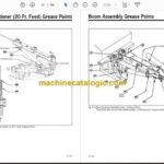
Grease Points – Positioner (20 Ft. Feed) …………………………………………………………………. 5-17
Grease Points – Boom Assembly …………………………………………………………………………… 5-18
Grease Points – Drill Console Boom (non-cab) …………………………………………………………… 5-19
Grease Points – Cab Mounting ………………………………………………………………………………. 5-20
Grease Points – Track Assembly ……………………………………………………………………………. 5-21
Grease Points – Headrest for 20 Ft. Feed ……………………………………………………………….. 5-22
Grease Points – Fan Drive, Caterpillar C10 & 11 Engine ……………………………………………… 5-22
Maintenance Record ……………………………………………………………………………………………. 5-23
Table of Contents
SECTION 4 DRILLING PROCEDURES
Final Checks ………………………………………………………………………………………………………. 4-9
Drilling Procedure ……………………………………………………………………………………………….. 4-10
Collaring the Hole ……………………………………………………………………………………………… 4-10
Collaring Circuit ………………………………………………………………………………………………… 4-13
Normal Drilling ……………………………………………………………………………………………………. 4-13
Drilling Practices …………………………………………………………………………………………………. 4-14
Collaring ………………………………………………………………………………………………………….. 4-14
Hole Deviation …………………………………………………………………………………………………… 4-14
Feed Pressure ………………………………………………………………………………………………….. 4-14
Drill Pressures ………………………………………………………………………………………………….. 4-14
Adjusting Drill Pressure and Monitioring the Machine …………………………………………………. 4-14
Plugged Bit and Stuck Drill Steel……………………………………………………………………………. 4-14
Anti-Jam System (optional) …………………………………………………………………………………….. 4-16
Reverse Percussion (optional) ………………………………………………………………………………… 4-18
Adding and Removing Drill Steel ……………………………………………………………………………… 4-20
Adding Drill Steel ……………………………………………………………………………………………….. 4-20
Removing Drill Steel …………………………………………………………………………………………… 4-21
Drill Shank Replacement ……………………………………………………………………………………….. 4-23
Indexing the Swing Cylinder …………………………………………………………………………………… 4-24
vi Introduction
SECTION 6 DRILL MAINTENANCE
Charging the Accumulators …………………………………………………………………………………….. 6-2
Requirements …………………………………………………………………………………………………….. 6-2
Procedure …………………………………………………………………………………………………………. 6-3
Checking the Accumulator Charge Pressure ……………………………………………………………….. 6-4
Accumulator Charge Kit …………………………………………………………………………………………. 6-6
Drill Lubrication …………………………………………………………………………………………………….. 6-7
Grease Lubrication with a Hand Grease Gun ……………………………………………………………… 6-7
Grease Specifications …………………………………………………………………………………………… 6-7
Automatic Lubrication…………………………………………………………………………………………… 6-7
Automatic Grease Lubricator Operation ……………………………………………………………………. 6-8
SECTION 7 DUST CONTROL
Health Hazard Warning …………………………………………………………………………………………… 7-1
Dust Collector Assembly ………………………………………………………………………………………… 7-2
Function of Dust Collector …………………………………………………………………………………….. 7-3
Detailed Function of Components……………………………………………………………………………. 7-3
Initial Start-up and Tuning ………………………………………………………………………………………. 7-4
Dust Collector Valve Adjustment (3306 engine) ………………………………………………………….. 7-5
Dust Collector Valve Adjustment (C10 & C11 engine)…………………………………………………… 7-6
Air Pressure Regulator Adjustment ………………………………………………………………………….. 7-7
Timer Adjustment ………………………………………………………………………………………………… 7-8
Fan Speed Adjustment ………………………………………………………………………………………….. 7-8
Filter Elements ………………………………………………………………………………………………….. 7-10
Dust Collector Efficiency …………………………………………………………………………………….. 7-10
Operational Variables ………………………………………………………………………………………….. 7-11
Fine Tuning ………………………………………………………………………………………………………..711
Manometer Setup Instructions ……………………………………………………………………………… 7-13
Timer Installation ………………………………………………………………………………………………. 7-14
To Set Timer …………………………………………………………………………………………………. 7-14
Control Circuit (Hydraulic, Electric and Air) ………………………………………………………………. 7-15
Fan Removal and Installation ………………………………………………………………………………… 7-16
Troubleshooting Hints ………………………………………………………………………………………… 7-17

