Format: PDF (Printable Document)
File Language: English
File Pages: 610
File Size: 70.38 MB (Speed Download Link)
Brand: Case
Model: Ecolo-Tiger 875 Mulch-Till Ripper
Part No: 90464111
Date: February 2021
Type of Document: Assembly Instructions
$ 55
Out in heavy tillage, the Ecolo-Tiger 875 is working deep in tough ground, breaking compaction and mixing residue in dusty, uneven fields. This assembly instructions manual is what I’d keep on hand when putting a new unit together or rebuilding one after major repairs. It walks you through how the machine is supposed to go together so you can align shanks, level frames, and mount wear parts correctly. When a customer complains the ripper is pulling crooked or not staying at consistent depth, I use this kind of document to verify how the components should be assembled and adjusted before chasing more complicated faults.
Applications & Use Cases
FAQ
Q: Can I use this manual on a tablet in the shop or field?
A: Yes, it’s practical to keep a digital copy on a tablet or phone so you can zoom in on diagrams while you work around the machine.
Q: Is it worth printing this manual?
A: I’d print the key assembly pages and keep them in a sleeve on the service truck, so they’re handy when you’re setting up or reassembling in the yard.
Safety Note
Always block and support the ripper securely before working underneath or around raised components.
1 SAFETY INFORMATION
Personal safety . . . . . . . . . . . . . . . . . . . . . . . . . . . . . . . . . . . . . . . . . . . . . . . . . . . . . . . . . . . . . . . . . . . . . . . . . . . . . 1-1
General information and safety. . . . . . . . . . . . . . . . . . . . . . . . . . . . . . . . . . . . . . . . . . . . . . . . . . . . . . . . . . . . . 1-2
2 GENERAL INFORMATION
Product overview . . . . . . . . . . . . . . . . . . . . . . . . . . . . . . . . . . . . . . . . . . . . . . . . . . . . . . . . . . . . . . . . . . . . . . . . . . . 2-1
Torque . . . . . . . . . . . . . . . . . . . . . . . . . . . . . . . . . . . . . . . . . . . . . . . . . . . . . . . . . . . . . . . . . . . . . . . . . . . . . . . . . . . . . . 2-3
Special bolt torque. . . . . . . . . . . . . . . . . . . . . . . . . . . . . . . . . . . . . . . . . . . . . . . . . . . . . . . . . . . . . . . . . . . . . . . . . . 2-8
Torque – Standard torque data for hydraulic connections . . . . . . . . . . . . . . . . . . . . . . . . . . . . . . . . . . 2-9
Ripper – Basic instructions. . . . . . . . . . . . . . . . . . . . . . . . . . . . . . . . . . . . . . . . . . . . . . . . . . . . . . . . . . . . . . . . . 2-16
Attaching the implement to the tractor. . . . . . . . . . . . . . . . . . . . . . . . . . . . . . . . . . . . . . . . . . . . . . . . . . . . . 2-17
Hydraulic hose connections – Standard frame control. . . . . . . . . . . . . . . . . . . . . . . . . . . . . . . . . . . . . 2-23
Hydraulic hose connections – Electronic frame control . . . . . . . . . . . . . . . . . . . . . . . . . . . . . . . . . . . . 2-25
3 PRE-ASSEMBLY
PREPARING FOR ASSEMBLY
Required building and equipment . . . . . . . . . . . . . . . . . . . . . . . . . . . . . . . . . . . . . . . . . . . . . . . . . . . . . . 3-1
Shipping package configurations . . . . . . . . . . . . . . . . . . . . . . . . . . . . . . . . . . . . . . . . . . . . . . . . . . . . . . . 3-2
Unpacking safety . . . . . . . . . . . . . . . . . . . . . . . . . . . . . . . . . . . . . . . . . . . . . . . . . . . . . . . . . . . . . . . . . . . . . . . 3-3
Unpacking the shipping packages. . . . . . . . . . . . . . . . . . . . . . . . . . . . . . . . . . . . . . . . . . . . . . . . . . . . . . 3-7
Remove shipping brackets . . . . . . . . . . . . . . . . . . . . . . . . . . . . . . . . . . . . . . . . . . . . . . . . . . . . . . . . . . . . . 3-8
Implement components. . . . . . . . . . . . . . . . . . . . . . . . . . . . . . . . . . . . . . . . . . . . . . . . . . . . . . . . . . . . . . . . . 3-9
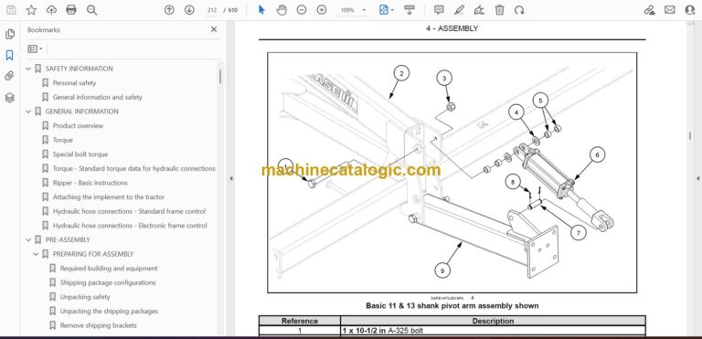
4 ASSEMBLY
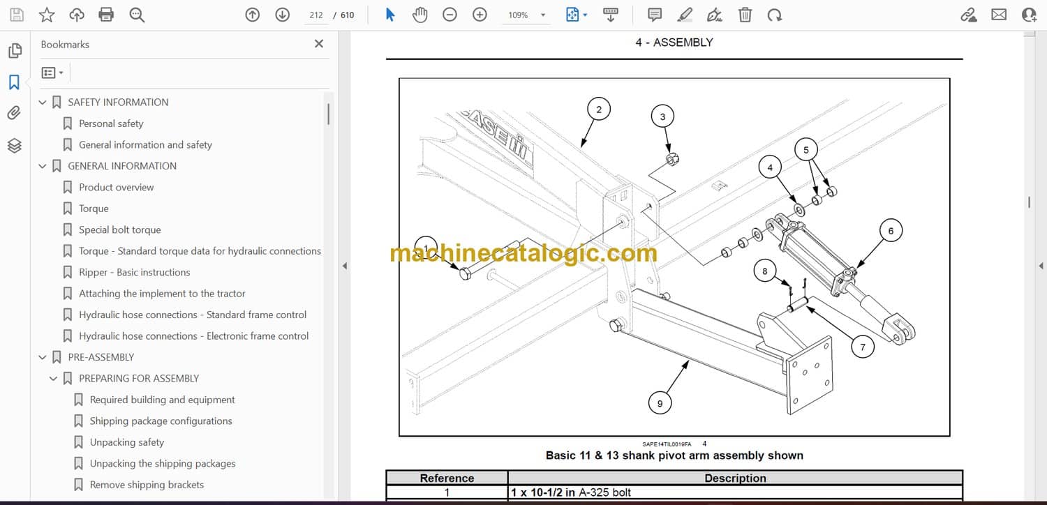
ASSEMBLY
Before assembly. . . . . . . . . . . . . . . . . . . . . . . . . . . . . . . . . . . . . . . . . . . . . . . . . . . . . . . . . . . . . . . . . . . . 4-1
Main frame assembly – Standard frame control . . . . . . . . . . . . . . . . . . . . . . . . . . . . . . . . . . . . 4-2
Main frame assembly – Electronic frame control . . . . . . . . . . . . . . . . . . . . . . . . . . . . . . . . . . . 4-5
Main frame lift cylinder installation – Standard frame control . . . . . . . . . . . . . . . . . . . . . . 4-16
Main frame lift cylinder installation – Electronic frame control . . . . . . . . . . . . . . . . . . . . . 4-22
Transport tire and wheel assembly . . . . . . . . . . . . . . . . . . . . . . . . . . . . . . . . . . . . . . . . . . . . . . . . 4-28
Position disk frame for assembly . . . . . . . . . . . . . . . . . . . . . . . . . . . . . . . . . . . . . . . . . . . . . . . . . . 4-29
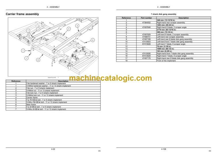
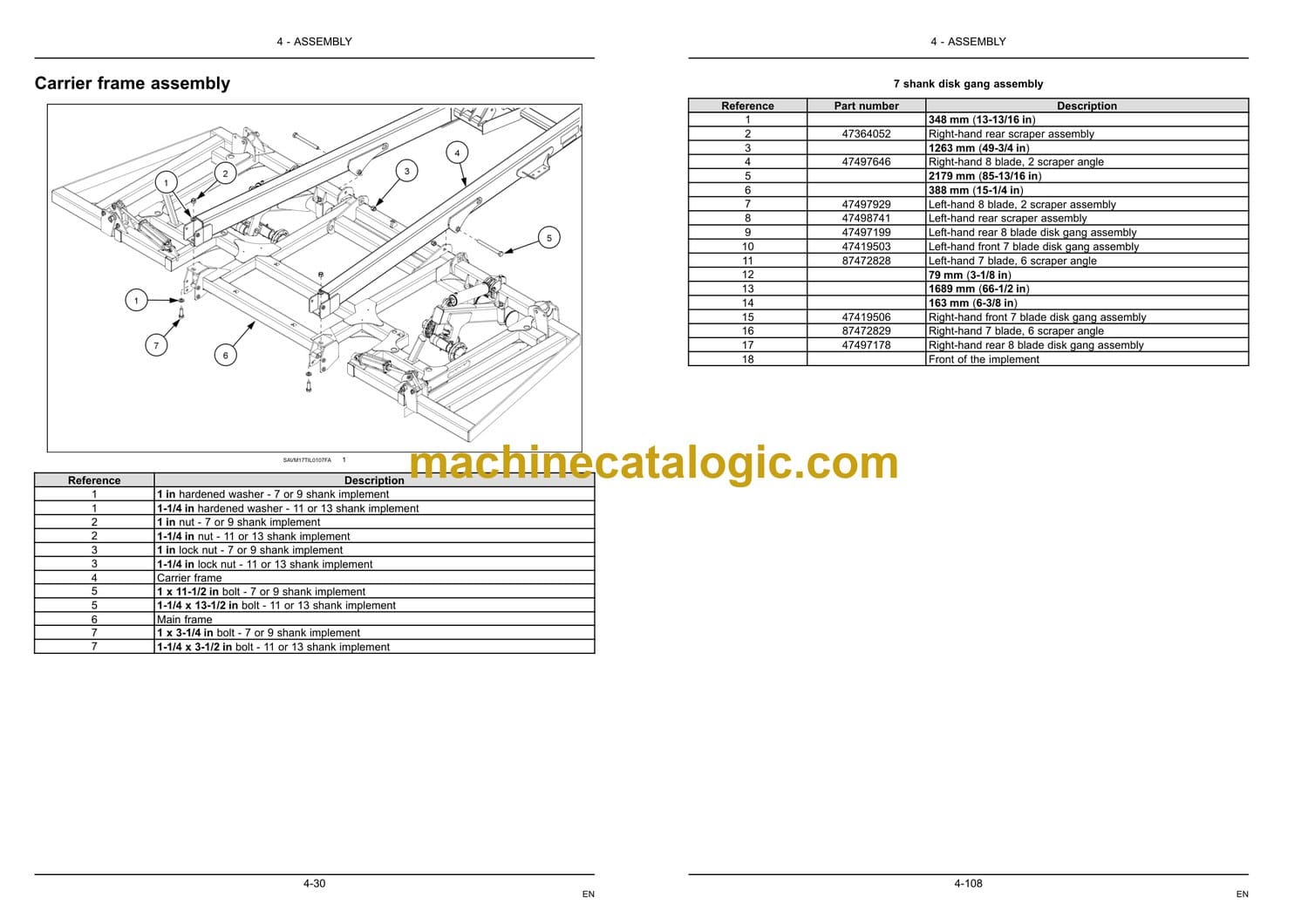
Carrier frame assembly. . . . . . . . . . . . . . . . . . . . . . . . . . . . . . . . . . . . . . . . . . . . . . . . . . . . . . . . . . . . 4-30
Universal Control Module (UCM) installation – Electronic frame control . . . . . . . . . . 4-32
Valve block installation for 7, 9 and 11 shank implements – Electronic frame control4-38
A-frame assembly – Standard frame control. . . . . . . . . . . . . . . . . . . . . . . . . . . . . . . . . . . . . . . 4-52
A-frame assembly – Electronic frame control . . . . . . . . . . . . . . . . . . . . . . . . . . . . . . . . . . . . . . 4-54
Jack installation. . . . . . . . . . . . . . . . . . . . . . . . . . . . . . . . . . . . . . . . . . . . . . . . . . . . . . . . . . . . . . . . . . . . 4-60
Swinging hose boom to A-frame assembly. . . . . . . . . . . . . . . . . . . . . . . . . . . . . . . . . . . . . . . . 4-61
Hitch weight plate kit to A-frame assembly . . . . . . . . . . . . . . . . . . . . . . . . . . . . . . . . . . . . . . . . 4-63
For 11 shank implements equipped with heavy duty coil tine harrow . 4-63
For S/R-13 shank implements equipped with deluxe leveling system 4-63
For 13 shank implements equipped with heavy duty coil tine harrow . 4-64
Single Point Depth Control (SPDC) assembly . . . . . . . . . . . . . . . . . . . . . . . . . . . . . . . . . . . . 4-65
Disk lift cylinder assembly – Standard frame control . . . . . . . . . . . . . . . . . . . . . . . . . . . . . . 4-72
7 or 9 shank carrier frame . . . . . . . . . . . . . . . . . . . . . . . . . . . . . . . . . . . . . . . . . . . . . 4-72
11 or 13 shank carrier frame. . . . . . . . . . . . . . . . . . . . . . . . . . . . . . . . . . . . . . . . . . . 4-74
Magnet and sensor installation – Electronic frame control. . . . . . . . . . . . . . . . . . . . . . . . . 4-76
Disk lift cylinder assembly – Electronic frame control. . . . . . . . . . . . . . . . . . . . . . . . . . . . . . 4-77
7 or 9 shank carrier frame . . . . . . . . . . . . . . . . . . . . . . . . . . . . . . . . . . . . . . . . . . . . . 4-77
11 or 13 shank carrier frame. . . . . . . . . . . . . . . . . . . . . . . . . . . . . . . . . . . . . . . . . . . 4-79
Disk frame to carrier frame assembly . . . . . . . . . . . . . . . . . . . . . . . . . . . . . . . . . . . . . . . . . . . . . 4-81
9 shank disk frame wing assembly . . . . . . . . . . . . . . . . . . . . . . . . . . . . . . . . . . . . . . . . . . . . . . . . 4-83
11 and 13 shank disk frame wing assembly . . . . . . . . . . . . . . . . . . . . . . . . . . . . . . . . . . . . . . . 4-88
Individual disk blade assembly . . . . . . . . . . . . . . . . . . . . . . . . . . . . . . . . . . . . . . . . . . . . . . . . . . . . 4-93
Individual disk blade mounting layouts . . . . . . . . . . . . . . . . . . . . . . . . . . . . . . . . . . . . . . . . . . . . 4-95
7 shank disk frame . . . . . . . . . . . . . . . . . . . . . . . . . . . . . . . . . . . . . . . . . . . . . . . . . . . . 4-95
9 shank disk frame . . . . . . . . . . . . . . . . . . . . . . . . . . . . . . . . . . . . . . . . . . . . . . . . . . . . 4-97
11 shank disk frame . . . . . . . . . . . . . . . . . . . . . . . . . . . . . . . . . . . . . . . . . . . . . . . . . . . 4-99
13 shank disk frame . . . . . . . . . . . . . . . . . . . . . . . . . . . . . . . . . . . . . . . . . . . . . . . . . . 4-101
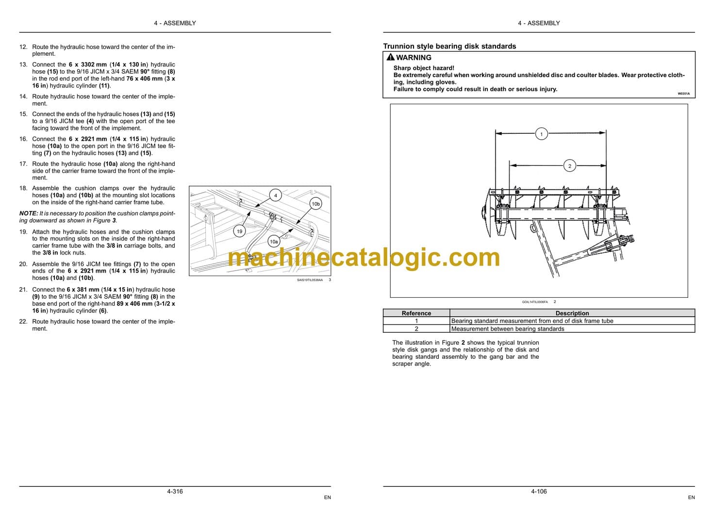
Cushion disk gang assembly . . . . . . . . . . . . . . . . . . . . . . . . . . . . . . . . . . . . . . . . . . . . . . . . . . . . . 4-103
Cushion disk gang layouts . . . . . . . . . . . . . . . . . . . . . . . . . . . . . . . . . . . . . . . . . . . . . . . . . . . . . . . 4-107
Disk scraper installation . . . . . . . . . . . . . . . . . . . . . . . . . . . . . . . . . . . . . . . . . . . . . . . . . . . . . . . . . . 4-117
11 shank main frame wing attachment . . . . . . . . . . . . . . . . . . . . . . . . . . . . . . . . . . . . . . . . . . . 4-120
13 shank main frame wing attachment . . . . . . . . . . . . . . . . . . . . . . . . . . . . . . . . . . . . . . . . . . . 4-124
Shank mount . . . . . . . . . . . . . . . . . . . . . . . . . . . . . . . . . . . . . . . . . . . . . . . . . . . . . . . . . . . . . . . . . . . . . 4-132
S/R-13 shank layouts. . . . . . . . . . . . . . . . . . . . . . . . . . . . . . . . . . . . . . . . . . . . . . . . . . . . . . . . . . . . . 4-136
7 shank implements . . . . . . . . . . . . . . . . . . . . . . . . . . . . . . . . . . . . . . . . . . . . . . . . . . 4-136
9 shank implements . . . . . . . . . . . . . . . . . . . . . . . . . . . . . . . . . . . . . . . . . . . . . . . . . . 4-138
Shear bolt shank layouts . . . . . . . . . . . . . . . . . . . . . . . . . . . . . . . . . . . . . . . . . . . . . . . . . . . . . . . . . 4-144
7 shank implements . . . . . . . . . . . . . . . . . . . . . . . . . . . . . . . . . . . . . . . . . . . . . . . . . . 4-144
9 shank implements with set back brackets . . . . . . . . . . . . . . . . . . . . . . . . . . 4-146
11 shank implements . . . . . . . . . . . . . . . . . . . . . . . . . . . . . . . . . . . . . . . . . . . . . . . . . 4-150
13 shank implements . . . . . . . . . . . . . . . . . . . . . . . . . . . . . . . . . . . . . . . . . . . . . . . . . 4-152
Ripper point to shank assembly . . . . . . . . . . . . . . . . . . . . . . . . . . . . . . . . . . . . . . . . . . . . . . . . . . 4-154
Wear shin to shank assembly (if equipped) . . . . . . . . . . . . . . . . . . . . . . . . . . . . . . . . . . . . . . 4-155
Coverboard to shank assembly (if equipped) . . . . . . . . . . . . . . . . . . . . . . . . . . . . . . . . . . . . 4-156
Rear disk leveler arm assembly . . . . . . . . . . . . . . . . . . . . . . . . . . . . . . . . . . . . . . . . . . . . . . . . . . 4-158
7 and 9 shank implements . . . . . . . . . . . . . . . . . . . . . . . . . . . . . . . . . . . . . . . . . . . 4-158
11 and 13 shank implements . . . . . . . . . . . . . . . . . . . . . . . . . . . . . . . . . . . . . . . . . 4-160
Rear disk leveler support tube assembly . . . . . . . . . . . . . . . . . . . . . . . . . . . . . . . . . . . . . . . . . 4-166
Rear disk leveler with finisher system arms . . . . . . . . . . . . . . . . . . . . . . . . . . . . . . . . . . . . . . 4-174
Rear disk leveler with finisher support frame assembly . . . . . . . . . . . . . . . . . . . . . . . . . . 4-180
Rear disk leveling arm assembly . . . . . . . . . . . . . . . . . . . . . . . . . . . . . . . . . . . . . . . . . . . . . . . . . 4-187
Rear disk leveler layouts . . . . . . . . . . . . . . . . . . . . . . . . . . . . . . . . . . . . . . . . . . . . . . . . . . . . . . . . . 4-191
Rear disk leveler layouts for heavy duty coil tine or spike harrows. . . . . . . . . . . . . . . 4-201
Rear disk leveler with spring arms . . . . . . . . . . . . . . . . . . . . . . . . . . . . . . . . . . . . . . . . . . . . . . . 4-211
Rear disk leveler with hydraulic basket lift. . . . . . . . . . . . . . . . . . . . . . . . . . . . . . . . . . . . . . . . 4-212
Rear disk leveler with hydraulic basket down pressure – Electronic frame control4-216
Formed bar basket assembly to rear arms . . . . . . . . . . . . . . . . . . . . . . . . . . . . . . . . . . . . . . . 4-220
Formed bar basket layouts . . . . . . . . . . . . . . . . . . . . . . . . . . . . . . . . . . . . . . . . . . . . . . . . . . . . . . . 4-223
Spike harrow leveler assembly . . . . . . . . . . . . . . . . . . . . . . . . . . . . . . . . . . . . . . . . . . . . . . . . . . . 4-233
11 and 13 shank spike harrow wing cross chain assembly . . . . . . . . . . . . . . . . . . . . . . 4-238
Spike harrow layouts . . . . . . . . . . . . . . . . . . . . . . . . . . . . . . . . . . . . . . . . . . . . . . . . . . . . . . . . . . . . . 4-240
EN
Heavy duty coil tine harrow assembly . . . . . . . . . . . . . . . . . . . . . . . . . . . . . . . . . . . . . . . . . . . . 4-248
Heavy duty coil tine harrow layouts . . . . . . . . . . . . . . . . . . . . . . . . . . . . . . . . . . . . . . . . . . . . . . 4-260
Hydraulic hoses to A-frame assembly. . . . . . . . . . . . . . . . . . . . . . . . . . . . . . . . . . . . . . . . . . . . 4-271
Fore/aft cylinder hydraulic fitting and hose assembly – Electronic frame control . 4-273
Single Point Depth Control (SPDC) hydraulic transport lift assembly – Standard frame
control . . . . . . . . . . . . . . . . . . . . . . . . . . . . . . . . . . . . . . . . . . . . . . . . . . . . . . . . . . . . . . . . . . . . . . . . . . . . 4-275
Main lift hydraulic hoses to main lift valve block – Electronic frame control . . . . . . 4-284
Main lift valve block to auxiliary valve block hydraulic hose connections – Electronic
frame control . . . . . . . . . . . . . . . . . . . . . . . . . . . . . . . . . . . . . . . . . . . . . . . . . . . . . . . . . . . . . . . . . . . . . 4-288
Valve block to tractor hydraulic hose connections – Electronic frame control . . . . 4-291
Basket down pressure adjustment valve hydraulic hose connections – Electronic frame
control . . . . . . . . . . . . . . . . . . . . . . . . . . . . . . . . . . . . . . . . . . . . . . . . . . . . . . . . . . . . . . . . . . . . . . . . . . . . 4-295
Disk depth hydraulics (with check valve) – Standard frame control . . . . . . . . . . . . . . 4-298
Disk depth hydraulics – Electronic frame control . . . . . . . . . . . . . . . . . . . . . . . . . . . . . . . . . 4-302
9 shank wing fold hydraulic assembly with basic leveling system. . . . . . . . . . . . . . . . 4-305
9 shank wing fold hydraulic assembly with leveling system and finisher . . . . . . . . . 4-313
11 and 13 shank wing fold hydraulic assembly. . . . . . . . . . . . . . . . . . . . . . . . . . . . . . . . . . . 4-320
11 shank wing fold hydraulic assembly with leveling system and finisher. . . . . . . . 4-330
13 shank wing fold hydraulic assembly with leveling system and finisher . . . . . . . 4-340
Basic and Deluxe leveling system lift hydraulics – Standard frame control. . . . . . . 4-350
Basic and Deluxe leveling system lift hydraulics – Electronic frame control . . . . . . 4-354
7 shank with leveler option hydraulic hose assembly . . . . . . . . . . . . . . . . . . . . . . . . . . . . 4-357
7 shank with leveler option hydraulic hose assembly – Electronic Frame Control 4-361
7 shank with leveler option hydraulic hose assembly – Electronic Frame Control
***NEW*** . . . . . . . . . . . . . . . . . . . . . . . . . . . . . . . . . . . . . . . . . . . . . . . . . . . . . . . . . . . . . . . . . . . . . . . . 4-366
9 shank with leveler option hydraulic hose assembly . . . . . . . . . . . . . . . . . . . . . . . . . . . . 4-382
9 shank with leveler option hydraulic hose assembly – Electronic frame control . 4-389
9 and 11 shank with leveler option hydraulic hose assembly – Electronic frame control
***NEW*** . . . . . . . . . . . . . . . . . . . . . . . . . . . . . . . . . . . . . . . . . . . . . . . . . . . . . . . . . . . . . . . . . . . . . . . . 4-403
11 shank with leveler option hydraulic hose assembly . . . . . . . . . . . . . . . . . . . . . . . . . . . 4-426
11 shank with leveler option hydraulic hose assembly – Electronic frame control 4-433
13 shank with leveler option hydraulic hose assembly . . . . . . . . . . . . . . . . . . . . . . . . . . . 4-445
Hydraulic hose bracket assembly . . . . . . . . . . . . . . . . . . . . . . . . . . . . . . . . . . . . . . . . . . . . . . . . 4-452
Hydraulic hose connections to the front of the implement. . . . . . . . . . . . . . . . . . . . . . . . 4-454
Hydraulic hose identification tags . . . . . . . . . . . . . . . . . . . . . . . . . . . . . . . . . . . . . . . . . . . . . . . . 4-456
Hydraulic hose identification tags – Electronic frame control . . . . . . . . . . . . . . . . . . . . . 4-458
Slow-Moving Vehicle (SMV) bracket and sign assembly . . . . . . . . . . . . . . . . . . . . . . . . . 4-460
Warning light and tail light installation . . . . . . . . . . . . . . . . . . . . . . . . . . . . . . . . . . . . . . . . . . . . 4-461
Red tail/stop light bracket assembly. . . . . . . . . . . . . . . . . . . . . . . . . . . . . . . . . . . . . . . . . . . . . . 4-464
Amber hazard light bracket assembly . . . . . . . . . . . . . . . . . . . . . . . . . . . . . . . . . . . . . . . . . . . . 4-466
Warning and tail light bracket locations for basic leveler . . . . . . . . . . . . . . . . . . . . . . . . . 4-468
7 shank implement . . . . . . . . . . . . . . . . . . . . . . . . . . . . . . . . . . . . . . . . . . . . . . . . . . . 4-468
9, 11, and 13 shank implements. . . . . . . . . . . . . . . . . . . . . . . . . . . . . . . . . . . . . . 4-474
Warning and tail light bracket locations for leveler with finisher . . . . . . . . . . . . . . . . . . 4-478
7 shank implement . . . . . . . . . . . . . . . . . . . . . . . . . . . . . . . . . . . . . . . . . . . . . . . . . . . 4-478
9, 11, and 13 shank implements. . . . . . . . . . . . . . . . . . . . . . . . . . . . . . . . . . . . . . 4-484
Warning and tail light wire routing diagram. . . . . . . . . . . . . . . . . . . . . . . . . . . . . . . . . . . . . . . 4-490
7 shank implements . . . . . . . . . . . . . . . . . . . . . . . . . . . . . . . . . . . . . . . . . . . . . . . . . . 4-490
9, 11, and 13 shank implements. . . . . . . . . . . . . . . . . . . . . . . . . . . . . . . . . . . . . . 4-491
Wiring harness installation – Electronic frame control . . . . . . . . . . . . . . . . . . . . . . . . . . . . 4-494
Wiring harness cable tie installation . . . . . . . . . . . . . . . . . . . . . . . . . . . . . . . . . . . . . . . . . . . . . . 4-505
Decal installation . . . . . . . . . . . . . . . . . . . . . . . . . . . . . . . . . . . . . . . . . . . . . . . . . . . . . . . . . . . . . . . . . 4-507
Safety stop installation . . . . . . . . . . . . . . . . . . . . . . . . . . . . . . . . . . . . . . . . . . . . . . . . . . . . . . . . . . . 4-508
7 shank hydraulic schematic – Electronic frame control . . . . . . . . . . . . . . . . . . . . . . . . . . 4-509
9, 11, and 13 shank hydraulic schematic – Electronic frame control. . . . . . . . . . . . . . 4-513
5 POST-ASSEMBLY
INSTRUCTIONS
Removing air from the hydraulic system – Standard frame control . . . . . . . . . . . . . . . . . . . . . 5-1
Initial load of software to Universal Control Module (UCM) with Electronic Service Tool
(EST) – Electronic frame control . . . . . . . . . . . . . . . . . . . . . . . . . . . . . . . . . . . . . . . . . . . . . . . . . . . . . . . . 5-3
Removing air from the hydraulic system – Electronic frame control . . . . . . . . . . . . . . . . . . . 5-20
Single point depth control adjustment . . . . . . . . . . . . . . . . . . . . . . . . . . . . . . . . . . . . . . . . . . . . . . . . . 5-21
Initial implement set-up . . . . . . . . . . . . . . . . . . . . . . . . . . . . . . . . . . . . . . . . . . . . . . . . . . . . . . . . . . . . . . . . 5-22
Purge the hydraulic system. . . . . . . . . . . . . . . . . . . . . . . . . . . . . . . . . . . . . . . . . . . . . . . . . . . . . . . . . . . . 5-28
Sensor calibration . . . . . . . . . . . . . . . . . . . . . . . . . . . . . . . . . . . . . . . . . . . . . . . . . . . . . . . . . . . . . . . . . . . . . 5-33
Valve calibration . . . . . . . . . . . . . . . . . . . . . . . . . . . . . . . . . . . . . . . . . . . . . . . . . . . . . . . . . . . . . . . . . . . . . . . 5-37
FINAL-CHECK
Assembly checklist . . . . . . . . . . . . . . . . . . . . . . . . . . . . . . . . . . . . . . . . . . . . . . . . . . . . . . . . . . . . . . . . . . . . 5-41


