Format: PDF (Printable Document)
File Language: English
File Pages: 532
File Size: 62.26 MB (Speed Download Link)
Brand: Case
Model: Tiger-Mate 255 Double Fold Constant Level Hitch Field Cultivator Drill
Part No: 91878697
Date: November 2022
Type of Document: Assembly Instructions
$ 45
1 SAFETY INFORMATION
Personal safety . . . . . . . . . . . . . . . . . . . . . . . . . . . . . . . . . . . . . . . . . . . . . . . . . . . . . . . . . . . . . . . . . . . . . . . . . . . . . 1-1
General information and safety. . . . . . . . . . . . . . . . . . . . . . . . . . . . . . . . . . . . . . . . . . . . . . . . . . . . . . . . . . . . . 1-2
2 GENERAL INFORMATION
Torque . . . . . . . . . . . . . . . . . . . . . . . . . . . . . . . . . . . . . . . . . . . . . . . . . . . . . . . . . . . . . . . . . . . . . . . . . . . . . . . . . . . . . . 2-1
Special bolt torque. . . . . . . . . . . . . . . . . . . . . . . . . . . . . . . . . . . . . . . . . . . . . . . . . . . . . . . . . . . . . . . . . . . . . . . . . . 2-7
Hose clamp and hydraulic hose assembly to the frame. . . . . . . . . . . . . . . . . . . . . . . . . . . . . . . . 2-7
Torque – Standard torque data for hydraulic connections . . . . . . . . . . . . . . . . . . . . . . . . . . . . . . . . . . 2-9
Soil preparation/Finishing – Basic instructions. . . . . . . . . . . . . . . . . . . . . . . . . . . . . . . . . . . . . . . . . . . . . 2-16
Attaching the implement to the tractor. . . . . . . . . . . . . . . . . . . . . . . . . . . . . . . . . . . . . . . . . . . . . . . . . . . . . 2-18
Hydraulic hose connections – Standard frame control. . . . . . . . . . . . . . . . . . . . . . . . . . . . . . . . . . . . . 2-23
Hydraulic hose connections – Electronic frame control . . . . . . . . . . . . . . . . . . . . . . . . . . . . . . . . . . . . 2-25
3 PRE-ASSEMBLY
PREPARING FOR ASSEMBLY
Shipping package configurations . . . . . . . . . . . . . . . . . . . . . . . . . . . . . . . . . . . . . . . . . . . . . . . . . . . . . . . 3-1
Main frame and wing packages . . . . . . . . . . . . . . . . . . . . . . . . . . . . . . . . . . . . . . . . . . . . . . . . . . . . . . . . 3-3
Unpacking the main frame package. . . . . . . . . . . . . . . . . . . . . . . . . . . . . . . . . . . . . . . . . . . . . . . . . . . . 3-5
Remove shipping brackets . . . . . . . . . . . . . . . . . . . . . . . . . . . . . . . . . . . . . . . . . . . . . . . . . . . . . . . . . . . . . 3-7
4 ASSEMBLY
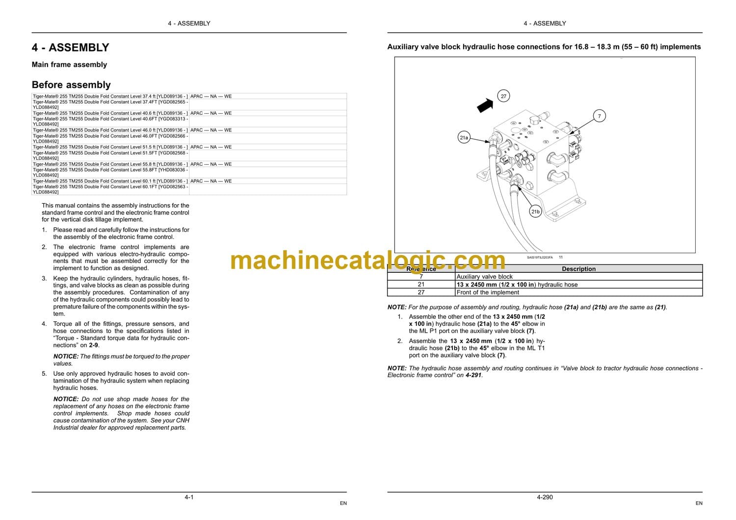
Main frame assembly
Before assembly. . . . . . . . . . . . . . . . . . . . . . . . . . . . . . . . . . . . . . . . . . . . . . . . . . . . . . . . . . . . . . . . . . . . 4-1
Main frame assembly – Standard frame control . . . . . . . . . . . . . . . . . . . . . . . . . . . . . . . . . . . . 4-3
Main frame assembly 11.3 -14.0 m (37 – 46 ft) – Electronic frame control. . . . . . . . . . 4-5
Main frame assembly 17.0 m and 18.3 m (55.8 and 60.1 ft) – Electronic frame control
. . . . . . . . . . . . . . . . . . . . . . . . . . . . . . . . . . . . . . . . . . . . . . . . . . . . . . . . . . . . . . . . . . . . . . . . . . . . . . . . . 4-19
Universal Control Module (UCM) installation – Electronic frame control . . . . . . . . . . 4-31
Valve block installation to main frame – Electronic frame control. . . . . . . . . . . . . . . . . . 4-37
Inner wing latch assembly . . . . . . . . . . . . . . . . . . . . . . . . . . . . . . . . . . . . . . . . . . . . . . . . . . . . . . . . . 4-43
Assemble lift system to main frame . . . . . . . . . . . . . . . . . . . . . . . . . . . . . . . . . . . . . . . . . . . . . . . 4-46
Assemble main frame lift rocker plates to main frame . . . . . . . . . . . . . . . . . . . . . . . . . . . . 4-51
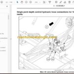
Single Point Depth Control (SPDC) . . . . . . . . . . . . . . . . . . . . . . . . . . . . . . . . . . . . . . . . . . . . . . . 4-53
Assemble constant level pull hitch to main frame – Standard frame control. . . . . . . 4-60
Assemble constant level pull hitch to main frame – Electronic frame control . . . . . . 4-69
Swinging hose boom to pull frame assembly. . . . . . . . . . . . . . . . . . . . . . . . . . . . . . . . . . . . . . 4-81
Inner wing frame to main frame assembly . . . . . . . . . . . . . . . . . . . . . . . . . . . . . . . . . . . . . . . . 4-83
3.6 m (11 ft) inner wings to main frame assembly . . . . . . . . . . . . . . . . . . . . . . . . . . . . . . . . . 4-96
Assemble outer wings to inner wings. . . . . . . . . . . . . . . . . . . . . . . . . . . . . . . . . . . . . . . . . . . . . 4-110
Assemble stub tubes to outer wing assembly for 12.2m, 15.5m, and 18.2m (40.6, 51.5,
and 60.1 ft) implements . . . . . . . . . . . . . . . . . . . . . . . . . . . . . . . . . . . . . . . . . . . . . . . . . . . . . . . . . . 4-120
Non-pivoting gauge wheel assembly . . . . . . . . . . . . . . . . . . . . . . . . . . . . . . . . . . . . . . . . . . . . . 4-122
Pivoting stabilizer wheel assembly . . . . . . . . . . . . . . . . . . . . . . . . . . . . . . . . . . . . . . . . . . . . . . . 4-128
Assemble shank mount. . . . . . . . . . . . . . . . . . . . . . . . . . . . . . . . . . . . . . . . . . . . . . . . . . . . . . . . . . . 4-136
Shank layout diagrams . . . . . . . . . . . . . . . . . . . . . . . . . . . . . . . . . . . . . . . . . . . . . . . . . . . . . . . . . . . 4-140
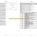
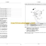
11.3 – 18.3 m (37 – 60 ft) hydraulic lift system assembly . . . . . . . . . . . . . . . . . . . . . . . . . 4-155
Hydraulic lift hose connections for 11.3 – 14.0 m (37 – 46 ft) implements – Standard
frame control . . . . . . . . . . . . . . . . . . . . . . . . . . . . . . . . . . . . . . . . . . . . . . . . . . . . . . . . . . . . . . . . . . . . . 4-181
Hydraulic lift hose connections for 11.3 – 14.0 m (37 – 46 ft) implements – Electronic
frame control . . . . . . . . . . . . . . . . . . . . . . . . . . . . . . . . . . . . . . . . . . . . . . . . . . . . . . . . . . . . . . . . . . . . . 4-197
Hydraulic lift hose connections for 15.5 m (51 ft) implements with standard fold option
– Electronic frame control . . . . . . . . . . . . . . . . . . . . . . . . . . . . . . . . . . . . . . . . . . . . . . . . . . . . . . . . . 4-215
Hydraulic lift hose connections for 15.5 – 18.3 m (51 – 60 ft) implements with narrow
fold option – Standard frame control . . . . . . . . . . . . . . . . . . . . . . . . . . . . . . . . . . . . . . . . . . . . . . 4-226
Hydraulic lift hose connections for 15.5 m (51 ft) implements with narrow fold option –
Electronic frame control . . . . . . . . . . . . . . . . . . . . . . . . . . . . . . . . . . . . . . . . . . . . . . . . . . . . . . . . . . 4-242
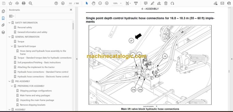
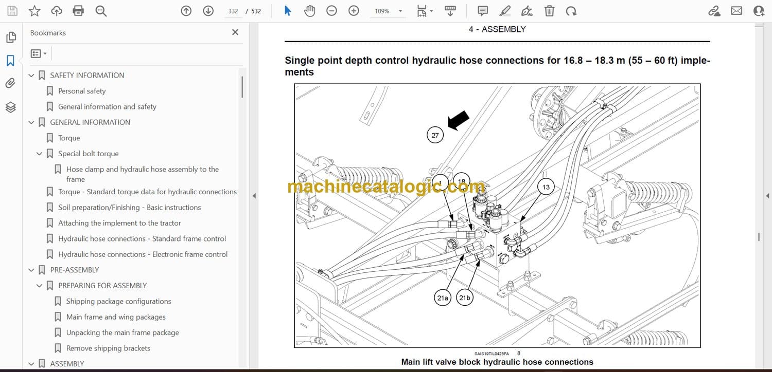
Hydraulic lift hose connections for 16.8 – 18.3 m (55 – 60 ft) implements with narrow
fold option – Electronic frame control . . . . . . . . . . . . . . . . . . . . . . . . . . . . . . . . . . . . . . . . . . . . . 4-256
Hydraulic lift hose connections for 15.5 – 18.3 m (51 – 60 ft) implements with standard
fold option – Standard frame control . . . . . . . . . . . . . . . . . . . . . . . . . . . . . . . . . . . . . . . . . . . . . . 4-270
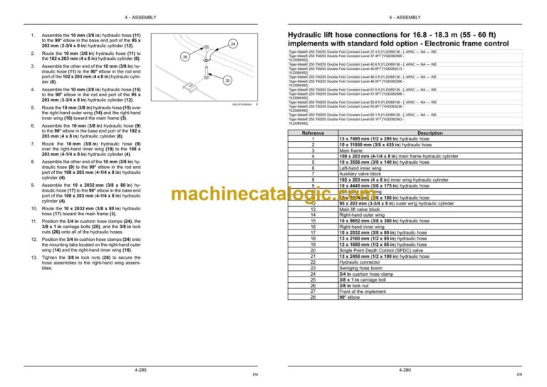
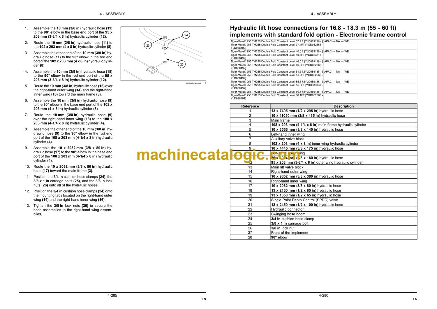
Hydraulic lift hose connections for 16.8 – 18.3 m (55 – 60 ft) implements with standard
fold option – Electronic frame control . . . . . . . . . . . . . . . . . . . . . . . . . . . . . . . . . . . . . . . . . . . . . 4-280
Valve block to tractor hydraulic hose connections – Electronic frame control . . . . 4-291
11.3 – 18.3 m (37 – 60 ft) hydraulic wing fold system . . . . . . . . . . . . . . . . . . . . . . . . . . . . . 4-296
Hydraulic wing fold hose connections for 11.3 – 14.0 m (37 – 46 ft) implements . 4-324
Hydraulic wing fold hose connections for 15.5 – 18.3 m (51 – 60ft) implements with
narrow fold option . . . . . . . . . . . . . . . . . . . . . . . . . . . . . . . . . . . . . . . . . . . . . . . . . . . . . . . . . . . . . . . . 4-339
Hydraulic wing fold hose connections for 15.5 – 18.3 m (51 – 60ft) implements with
standard fold option . . . . . . . . . . . . . . . . . . . . . . . . . . . . . . . . . . . . . . . . . . . . . . . . . . . . . . . . . . . . . . 4-361
Hydraulic hose identification tags – Standard frame control . . . . . . . . . . . . . . . . . . . . . . 4-382
Hydraulic hose identification tags – Electronic frame control . . . . . . . . . . . . . . . . . . . . . 4-384
Red tail/stop light bracket assembly. . . . . . . . . . . . . . . . . . . . . . . . . . . . . . . . . . . . . . . . . . . . . . 4-387
Amber hazard light bracket assembly . . . . . . . . . . . . . . . . . . . . . . . . . . . . . . . . . . . . . . . . . . . . 4-389
Slow Moving Vehicle (SMV) emblem kit. . . . . . . . . . . . . . . . . . . . . . . . . . . . . . . . . . . . . . . . . . 4-391
Warning light and tail light installation . . . . . . . . . . . . . . . . . . . . . . . . . . . . . . . . . . . . . . . . . . . . 4-396
Wiring harness installation – Electronic frame control . . . . . . . . . . . . . . . . . . . . . . . . . . . . 4-405
Wiring harness cable tie installation . . . . . . . . . . . . . . . . . . . . . . . . . . . . . . . . . . . . . . . . . . . . . . 4-415
Hydraulic schematics – Standard frame control . . . . . . . . . . . . . . . . . . . . . . . . . . . . . . . . . . 4-417
Hydraulic schematics – Electronic frame control . . . . . . . . . . . . . . . . . . . . . . . . . . . . . . . . . 4-439
5 POST-ASSEMBLY
INSTRUCTIONS
Removing air from the hydraulic system – Standard frame control . . . . . . . . . . . . . . . . . . . . . 5-1
Initial load of software to Universal Control Module (UCM) with Electronic Service Tool
(EST) – Electronic frame control . . . . . . . . . . . . . . . . . . . . . . . . . . . . . . . . . . . . . . . . . . . . . . . . . . . . . . . . 5-5
Removing air from the hydraulic system – Electronic frame control . . . . . . . . . . . . . . . . . . . 5-22
Single Point Depth Control (SPDC) adjustment . . . . . . . . . . . . . . . . . . . . . . . . . . . . . . . . . . . . . . . 5-24
FINAL-CHECK
Assembly checklist . . . . . . . . . . . . . . . . . . . . . . . . . . . . . . . . . . . . . . . . . . . . . . . . . . . . . . . . . . . . . . . . . . . . 5-26

