Format: PDF (Printable Document)
File Language: English
File Pages: 614
File Size: 53.09 MB (Speed Download Link)
Brand: Case
Model: True-Tandem 335VT 22-34 Foot Vertical Tillage
Part No: 92318827
Date: December 2024
Type of Document: Assembly Instructions
$ 45
1 SAFETY INFORMATION
Personal safety . . . . . . . . . . . . . . . . . . . . . . . . . . . . . . . . . . . . . . . . . . . . . . . . . . . . . . . . . . . . . . . . . . . . . . . . . . . . . 1-1
General information and safety. . . . . . . . . . . . . . . . . . . . . . . . . . . . . . . . . . . . . . . . . . . . . . . . . . . . . . . . . . . . . 1-2
2 GENERAL INFORMATION
Product overview . . . . . . . . . . . . . . . . . . . . . . . . . . . . . . . . . . . . . . . . . . . . . . . . . . . . . . . . . . . . . . . . . . . . . . . . . . . 2-1
Torque . . . . . . . . . . . . . . . . . . . . . . . . . . . . . . . . . . . . . . . . . . . . . . . . . . . . . . . . . . . . . . . . . . . . . . . . . . . . . . . . . . . . . . 2-4
Special bolt torque. . . . . . . . . . . . . . . . . . . . . . . . . . . . . . . . . . . . . . . . . . . . . . . . . . . . . . . . . . . . . . . . . . . . . . . . . . 2-9
Torque – Standard torque data for hydraulic connections . . . . . . . . . . . . . . . . . . . . . . . . . . . . . . . . . 2-10
Soil preparation/Finishing – Basic instructions. . . . . . . . . . . . . . . . . . . . . . . . . . . . . . . . . . . . . . . . . . . . . 2-17
Attaching the implement to the tractor. . . . . . . . . . . . . . . . . . . . . . . . . . . . . . . . . . . . . . . . . . . . . . . . . . . . . 2-18
Hydraulic hose connections – Standard frame control. . . . . . . . . . . . . . . . . . . . . . . . . . . . . . . . . . . . . 2-24
Hydraulic hose connections – Electronic frame control . . . . . . . . . . . . . . . . . . . . . . . . . . . . . . . . . . . . 2-26
3 PRE-ASSEMBLY
PREPARING FOR ASSEMBLY
Required building and equipment . . . . . . . . . . . . . . . . . . . . . . . . . . . . . . . . . . . . . . . . . . . . . . . . . . . . . . 3-1
Shipping package configurations . . . . . . . . . . . . . . . . . . . . . . . . . . . . . . . . . . . . . . . . . . . . . . . . . . . . . . . 3-2
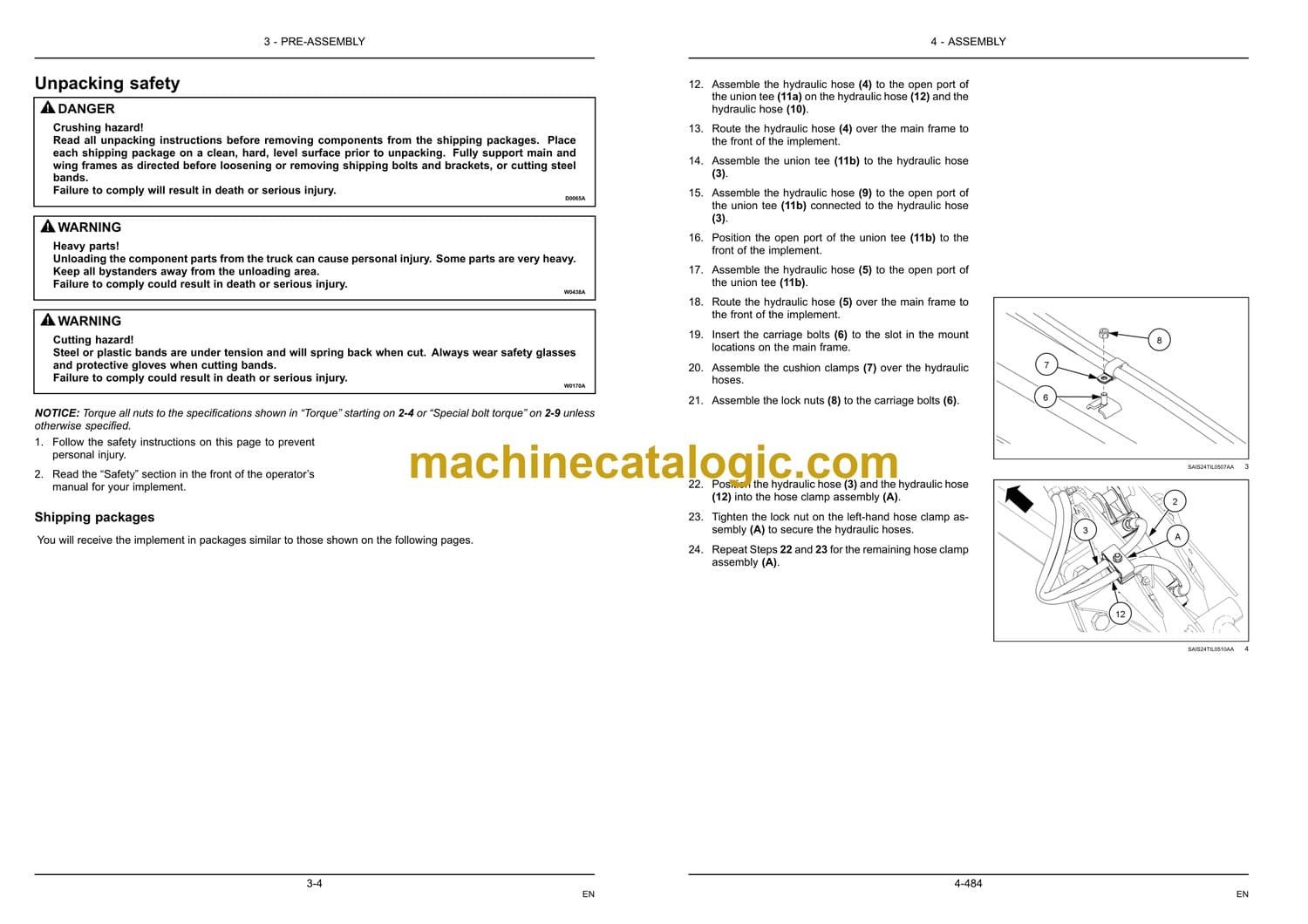
Unpacking safety . . . . . . . . . . . . . . . . . . . . . . . . . . . . . . . . . . . . . . . . . . . . . . . . . . . . . . . . . . . . . . . . . . . . . . . 3-4
Unpacking the shipping packages. . . . . . . . . . . . . . . . . . . . . . . . . . . . . . . . . . . . . . . . . . . . . . . . . . . . . . 3-5
Removing the shipping brackets . . . . . . . . . . . . . . . . . . . . . . . . . . . . . . . . . . . . . . . . . . . . . . . . . . . . . . . 3-6
Unpacking one-piece main frame and pull frame . . . . . . . . . . . . . . . . . . . . . . . . . . . . . . . . . . . . . . 3-7
4 ASSEMBLY
ASSEMBLY
Before assembly. . . . . . . . . . . . . . . . . . . . . . . . . . . . . . . . . . . . . . . . . . . . . . . . . . . . . . . . . . . . . . . . . . . . 4-1
Main frame assembly. . . . . . . . . . . . . . . . . . . . . . . . . . . . . . . . . . . . . . . . . . . . . . . . . . . . . . . . . . . . . . . 4-2
Universal Control Module (UCM) installation – Electronic frame control . . . . . . . . . . . 4-3
Main lift valve block assembly to main frame – Electronic frame control . . . . . . . . . . . 4-9
Transport hub and spindle installation. . . . . . . . . . . . . . . . . . . . . . . . . . . . . . . . . . . . . . . . . . . . . 4-16
Main frame lift cylinder installation – Standard frame control . . . . . . . . . . . . . . . . . . . . . . 4-17
Main frame lift cylinder installation – Electronic frame control . . . . . . . . . . . . . . . . . . . . . 4-21
Center coulter assembly. . . . . . . . . . . . . . . . . . . . . . . . . . . . . . . . . . . . . . . . . . . . . . . . . . . . . . . . . . . 4-25
Coulter assembly for 6.7 – 9.4 m (22 – 31 ft) implements . . . . . . . . . . . . 4-25
Coulter assembly for 10.4 m (34 ft) implement. . . . . . . . . . . . . . . . . . . . . . . . 4-28
Decal installation . . . . . . . . . . . . . . . . . . . . . . . . . . . . . . . . . . . . . . . . . . . . . . . . . . . . . . . . . . . . . . . . . . 4-33
6.7 – 9.4 m (22 – 31 ft) main frame disk gang installation. . . . . . . . . . . . . . . . . . . . . . . . . . 4-35
10.4 m (34 ft) main frame disk gang installation. . . . . . . . . . . . . . . . . . . . . . . . . . . . . . . . . . . 4-37
Main frame disk gang identification. . . . . . . . . . . . . . . . . . . . . . . . . . . . . . . . . . . . . . . . . . . . . . . . 4-43
Wing frame to main frame assembly . . . . . . . . . . . . . . . . . . . . . . . . . . . . . . . . . . . . . . . . . . . . . . 4-49
Wing frame disk gang identification . . . . . . . . . . . . . . . . . . . . . . . . . . . . . . . . . . . . . . . . . . . . . . . 4-51
Disk scraper installation . . . . . . . . . . . . . . . . . . . . . . . . . . . . . . . . . . . . . . . . . . . . . . . . . . . . . . . . . . . 4-61
Wing frame eye bolt installation . . . . . . . . . . . . . . . . . . . . . . . . . . . . . . . . . . . . . . . . . . . . . . . . . . . 4-65
Wing frame lift cylinder installation – Standard frame control. . . . . . . . . . . . . . . . . . . . . . 4-67
Wing frame lift cylinder installation – Electronic frame control . . . . . . . . . . . . . . . . . . . . . 4-71
6.7 – 9.4 m (22 – 31 ft) wing stop installation . . . . . . . . . . . . . . . . . . . . . . . . . . . . . . . . . . . . . . 4-75
10.4 m (34 ft) wing stop installation . . . . . . . . . . . . . . . . . . . . . . . . . . . . . . . . . . . . . . . . . . . . . . . 4-79
Spring leveling link assembly installation. . . . . . . . . . . . . . . . . . . . . . . . . . . . . . . . . . . . . . . . . . 4-82
Single Point Depth Control (SPDC) assembly . . . . . . . . . . . . . . . . . . . . . . . . . . . . . . . . . . . . 4-85
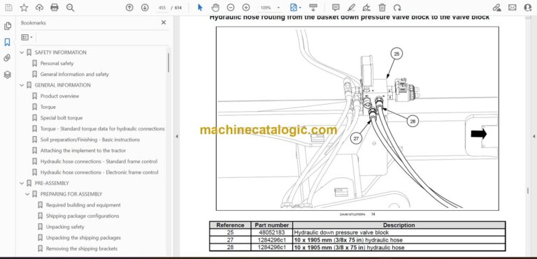
Single basket down pressure valve block installation – Standard frame control. . . 4-90
Single basket down pressure valve block installation – Electronic frame control . . 4-92
Pull frame to main frame assembly. . . . . . . . . . . . . . . . . . . . . . . . . . . . . . . . . . . . . . . . . . . . . . . . 4-95
Jack installation. . . . . . . . . . . . . . . . . . . . . . . . . . . . . . . . . . . . . . . . . . . . . . . . . . . . . . . . . . . . . . . . . . . 4-102
Swinging hose boom to pull frame assembly. . . . . . . . . . . . . . . . . . . . . . . . . . . . . . . . . . . . . 4-103
Auxiliary valve block installation to pull frame – Electronic frame control. . . . . . . . . 4-105
Fore/aft cylinder hydraulic fitting and hose assembly – Standard frame control. . 4-111
Fore/aft cylinder hydraulic fitting and hose assembly – Electronic frame control . 4-122
Main frame and wing frame lift hydraulic hose installation – Standard frame control4-128
Main frame and wing frame lift hydraulic hose installation – Electronic frame control
. . . . . . . . . . . . . . . . . . . . . . . . . . . . . . . . . . . . . . . . . . . . . . . . . . . . . . . . . . . . . . . . . . . . . . . . . . . . . . . . 4-167
Hydraulic hose support bracket installation . . . . . . . . . . . . . . . . . . . . . . . . . . . . . . . . . . . . . . 4-185
Single Point Depth Control (SPDC) hydraulic hose installation – Electronic frame control
. . . . . . . . . . . . . . . . . . . . . . . . . . . . . . . . . . . . . . . . . . . . . . . . . . . . . . . . . . . . . . . . . . . . . . . . . . . . . . . . 4-188
Main lift valve block to auxiliary valve block hydraulic hose connections – Electronic
frame control . . . . . . . . . . . . . . . . . . . . . . . . . . . . . . . . . . . . . . . . . . . . . . . . . . . . . . . . . . . . . . . . . . . . . 4-194
Auxiliary valve block to tractor hydraulic hose connections – Electronic frame control
. . . . . . . . . . . . . . . . . . . . . . . . . . . . . . . . . . . . . . . . . . . . . . . . . . . . . . . . . . . . . . . . . . . . . . . . . . . . . . . . 4-198
Wing fold hydraulics . . . . . . . . . . . . . . . . . . . . . . . . . . . . . . . . . . . . . . . . . . . . . . . . . . . . . . . . . . . . . . 4-202
Hydraulic hose identification tags – Standard frame control . . . . . . . . . . . . . . . . . . . . . . 4-223
Hydraulic hose identification tags – Electronic frame control . . . . . . . . . . . . . . . . . . . . . 4-225
Warning light and tail light installation . . . . . . . . . . . . . . . . . . . . . . . . . . . . . . . . . . . . . . . . . . . . 4-227
Red tail/stop light bracket assembly. . . . . . . . . . . . . . . . . . . . . . . . . . . . . . . . . . . . . . . . . . . . . . 4-230
Amber hazard light bracket assembly . . . . . . . . . . . . . . . . . . . . . . . . . . . . . . . . . . . . . . . . . . . . 4-232
Slow-Moving Vehicle (SMV) bracket and sign assembly . . . . . . . . . . . . . . . . . . . . . . . . . 4-234
Safety lighting installation . . . . . . . . . . . . . . . . . . . . . . . . . . . . . . . . . . . . . . . . . . . . . . . . . . . . . . . . 4-236
6.7 m (22 ft) and 7.6 m (25 ft) implements . . . . . . . . . . . . . . . . . . . . . . . . . . . 4-236
8.5 m (28 ft) and 9.4 m (31 ft) implements . . . . . . . . . . . . . . . . . . . . . . . . . . . 4-240
10.4 m (34 ft) implements . . . . . . . . . . . . . . . . . . . . . . . . . . . . . . . . . . . . . . . . . . . . 4-245
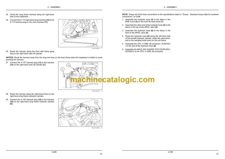
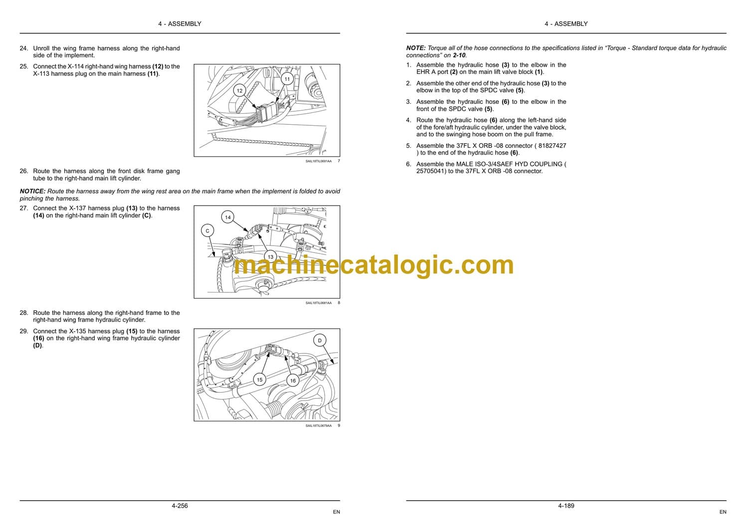
Wiring harness installation – Electronic frame control . . . . . . . . . . . . . . . . . . . . . . . . . . . . 4-252
Wiring harness cable tie installation . . . . . . . . . . . . . . . . . . . . . . . . . . . . . . . . . . . . . . . . . . . . . . 4-262
Pivoting stabilizer wheel assembly . . . . . . . . . . . . . . . . . . . . . . . . . . . . . . . . . . . . . . . . . . . . . . . 4-264
Single roller basket frame attachment tubes . . . . . . . . . . . . . . . . . . . . . . . . . . . . . . . . . . . . . 4-268
Installation for 6.7 – 7.6 m (22 – 25 ft) implements . . . . . . . . . . . . . . . . . . 4-268
Installation for 8.5 – 9.4 m (28 – 31 ft) implements . . . . . . . . . . . . . . . . . . 4-272
Installation for 10.4 m (34 ft) implement. . . . . . . . . . . . . . . . . . . . . . . . . . . . . . 4-276
Double roller basket frame attachment tubes . . . . . . . . . . . . . . . . . . . . . . . . . . . . . . . . . . . . 4-280
Frame attachment tube Installation for 6.7 m (22 ft) implements . . . . 4-280
Frame attachment tube Installation for 7.6 m (25 ft) implements . . . . 4-283
Frame attachment tube Installation for 8.5 m (28 ft) implements . . . . 4-286
Frame attachment tube Installation for 9.4 m (31 ft) implements . . . . 4-289
Installation for 10.4 m (34 ft) implements . . . . . . . . . . . . . . . . . . . . . . . . . . . . 4-292
Single roller basket arm and hydraulic cylinder install. . . . . . . . . . . . . . . . . . . . . . . . . . . . 4-295
Double roller basket arm install. . . . . . . . . . . . . . . . . . . . . . . . . . . . . . . . . . . . . . . . . . . . . . . . . . . 4-298
Single roller basket arm and hydraulic cylinder install. . . . . . . . . . . . . . . . . . . . . . . . . . . . 4-308
Double roller basket arm install. . . . . . . . . . . . . . . . . . . . . . . . . . . . . . . . . . . . . . . . . . . . . . . . . . . 4-313
6.7 – 7.6 m (22 – 25 ft) single basket leveler hydraulic routing – Standard frame control
. . . . . . . . . . . . . . . . . . . . . . . . . . . . . . . . . . . . . . . . . . . . . . . . . . . . . . . . . . . . . . . . . . . . . . . . . . . . . . . . 4-318
6.7 (22 ft) and 7.6 m (25 ft) single basket leveler hydraulic routing – Electronic frame
control . . . . . . . . . . . . . . . . . . . . . . . . . . . . . . . . . . . . . . . . . . . . . . . . . . . . . . . . . . . . . . . . . . . . . . . . . . . . 4-332
6.7 m (22 ft) double basket leveler hydraulic routing – Electronic frame control. . 4-345
7.6 m (25 ft) double basket leveler hydraulic routing – Electronic frame control. . 4-358
8.5 m (28 ft) single basket leveler hydraulic routing – Standard frame control . . . 4-371
8.5 m (28 ft) single basket leveler hydraulic routing – Electronic frame control. . . 4-385
8.5 m (28 ft) double basket leveler hydraulic routing – Electronic frame control. . 4-398
9.4 m (31 ft) single basket leveler hydraulic routing – Standard frame control . . . 4-411
9.4 m (31 ft) single basket leveler hydraulic routing – Electronic frame control. . . 4-426
9.4 m (31 ft) double basket leveler hydraulic routing – Electronic frame control. . 4-440
10.4 m (34 ft) single basket leveler hydraulic routing -Standard frame control. . . 4-453
10.4 m (34 ft) single basket leveler hydraulic routing – Electronic frame control . 4-468
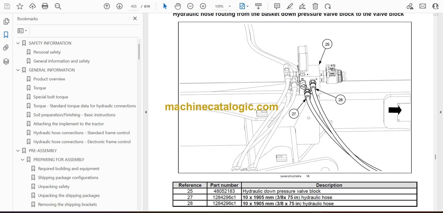
10.4 m (34 ft) double basket leveler hydraulic routing – Electronic frame control 4-482
Decal installation . . . . . . . . . . . . . . . . . . . . . . . . . . . . . . . . . . . . . . . . . . . . . . . . . . . . . . . . . . . . . . . . . 4-495
Single basket to leveler arm assembly . . . . . . . . . . . . . . . . . . . . . . . . . . . . . . . . . . . . . . . . . . . 4-497
6.7 m (22 ft) single basket size and location . . . . . . . . . . . . . . . . . . . . . . . . . 4-499
7.6 m (25 ft) single basket size and location . . . . . . . . . . . . . . . . . . . . . . . . . 4-500
8.5 m (28 ft) single basket size and location . . . . . . . . . . . . . . . . . . . . . . . . . 4-501
9.4 m (31 ft) single basket size and location . . . . . . . . . . . . . . . . . . . . . . . . . 4-502
10.4 m (34 ft) single basket size and location. . . . . . . . . . . . . . . . . . . . . . . . 4-503
Double basket to leveler arm assembly . . . . . . . . . . . . . . . . . . . . . . . . . . . . . . . . . . . . . . . . . . 4-504
Coil tine harrow assembly . . . . . . . . . . . . . . . . . . . . . . . . . . . . . . . . . . . . . . . . . . . . . . . . . . . . . . . . 4-511
Coil tine harrow layouts. . . . . . . . . . . . . . . . . . . . . . . . . . . . . . . . . . . . . . . . . . . . . . . . . . . . . . . . . . . 4-517
Optional rear jack stand . . . . . . . . . . . . . . . . . . . . . . . . . . . . . . . . . . . . . . . . . . . . . . . . . . . . . . . . . . 4-531
Hydraulic schematic – Electronic frame control. . . . . . . . . . . . . . . . . . . . . . . . . . . . . . . . . . . 4-533
5 POST-ASSEMBLY
INSTRUCTIONS
Removing air from the hydraulic system – Standard frame control . . . . . . . . . . . . . . . . . . . . . 5-1
Initial load of software to Universal Control Module (UCM) with Electronic Service Tool
(EST) – Electronic frame control . . . . . . . . . . . . . . . . . . . . . . . . . . . . . . . . . . . . . . . . . . . . . . . . . . . . . . . . 5-4
Removing air from the hydraulic system – Electronic frame control . . . . . . . . . . . . . . . . . . . 5-21
Single point depth control adjustment . . . . . . . . . . . . . . . . . . . . . . . . . . . . . . . . . . . . . . . . . . . . . . . . . 5-23
Initial implement set-up . . . . . . . . . . . . . . . . . . . . . . . . . . . . . . . . . . . . . . . . . . . . . . . . . . . . . . . . . . . . . . . . 5-24
FINAL-CHECK
Assembly checklist . . . . . . . . . . . . . . . . . . . . . . . . . . . . . . . . . . . . . . . . . . . . . . . . . . . . . . . . . . . . . . . . . . . . 5-25

