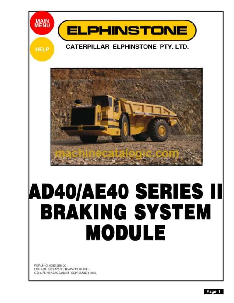
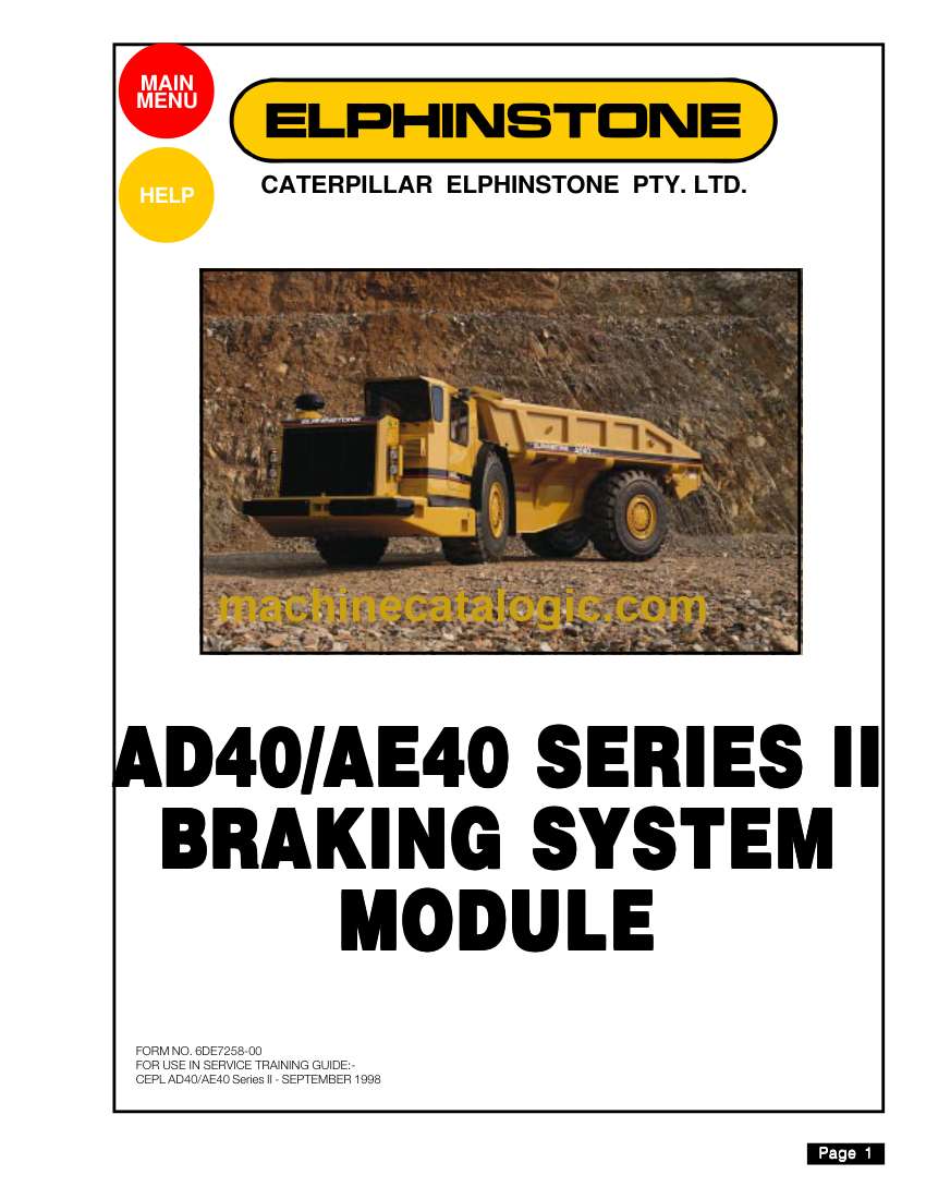
Cat AD40, AE40 Dump Truck Operation and Maintenance Manual
These AD40/AE40 trucks usually live underground or in tight quarry runs, hauling heavy rock all shift in heat, mud, dust, and bad footing. This operation and maintenance manual helps you set a steady service rhythm so the truck behaves the same on Monday morning as it does at the end of a night shift. Say the retarder starts to feel weak on a long downhill—this book walks you through what to check, how to trace the fault, and when to park it before it becomes a runaway problem.
Applications & Use Cases
- Set up daily walk‑around checks so you trace leaks, loose hardware, and tire issues before the operator even climbs in.
- Plan weekly and seasonal services to inspect brakes, test steering, and verify hydraulic health, instead of waiting for something to fail in the heading.
- Follow step‑by‑step procedures to bleed and align the braking system when the pedal feel changes or you’ve done component work.
- Use the lube and filter intervals to route your maintenance crew efficiently, so you don’t have three trucks down the same day.
- Isolate recurring faults by checking systems in the order the manual lays out, rather than guessing and throwing parts at it.
FAQ
Q: Is this manual searchable on a laptop or tablet, or am I stuck flipping pages?
A: You’ll typically get a searchable PDF, so you can jump to systems or keywords fast, which is handy when you’re under time pressure.
Q: Can I print sections to keep in the shop or carry underground?
A: Yes, most folks print the service routines and fluid charts they use most, then keep the full file on a computer for reference.
Safety Note
Always verify the truck is blocked, tagged out, and pressure bled off before you crawl under or crack a hydraulic or brake line.
Cat AD40, AE40 Dump Truck Index:
- List of Contents
- Important Safety Notice
- AD40/AE40 Series II Braking System Overview
- Introduction
- Braking System Component Location
- Brake Controls
- Parking Brake System
- Parking Brake Circuit
- Parking Brake Control Valve Group
- Parking Brake Circuit (Brake Engaged)
- Parking Brake Circuit (Brake Released)
- Parking Brake Release Circuit
- Parking Brake Release Electrical Circuit Schematic (Power Supply)
- Parking Brake Release Electrical Circuit Schematic (Relay Latched)
- Service and Retarder Brake System
- Service and Retarder Brake Circuit – Accumulator Charging Circuit
- Service and Retarder Brake Circuit – Accumulator Charging Circuit
- Accumulator Charging Valve (Accumulator Fully Charged – Cut-Out Cycle)
- Accumulator Charging Valve (Accumulator Being Charged – Cut-In Cycle)
- Brake Accumulator
- Service and Retarder Brake Circuit – Brake Application Circuit
- Service Brake Control Valve (Released Position)
- Service Brake Control Valve (Applied Position)
- Slack Adjusters
- Wheel Brake Unit (Typical Illustration)
- Wheel Brake (Parking Brake Released)
- Wheel Brake (Parking Brake Released – Service Brake Applied)
- Service Brake Circuit (Brakes Released)
- Service Brake Circuit (Brakes Applied)
- Service Brake Circuit (Brakes Held Applied)
- Automatic Retarder Control Circuit (ARC)
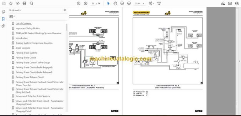
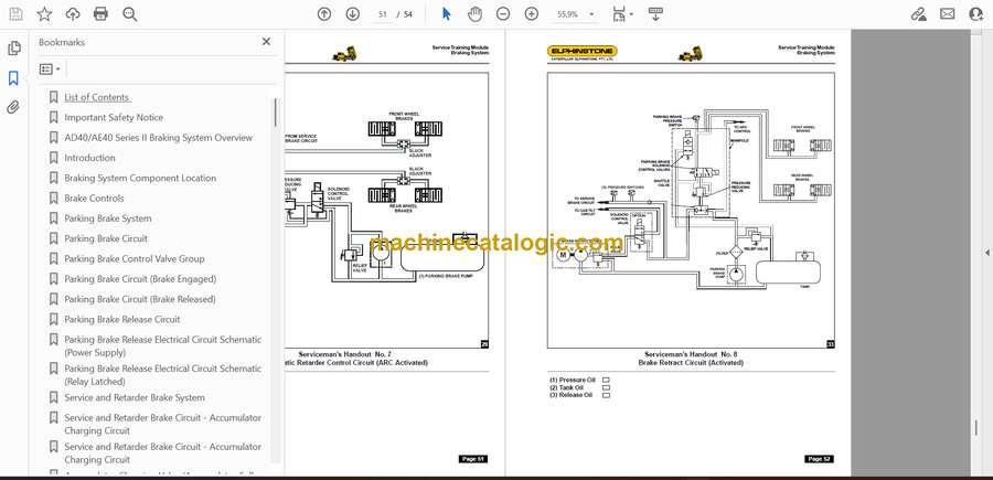
- Automatic Retarder Control Circuit (ARC Activated)
- Stop Light/Residual Brake Pressure Electrical Circuit
- Stop Light/Residual Brake Pressure Circuit Electrical Schematic
- Brake Retract Circuit
- Brake Retract Circuit (Activated)
- Brake Oil Cooling System
- Brake Oil Cooling Circuit
- Checking The Accumulator Charging Valve Cut-In and Cut-Out Pressure (Practical Task)
- Theory Assessment
- Theory Assessment Answers
- Serviceman’s Handouts
- REPAGE.pdf
- List of Contents
- Important Safety Notice
- AD40/AE40 Series II Braking System Overview
- Introduction
- Braking System Component Location
- Brake Controls
- Parking Brake System
- Parking Brake Circuit
- Parking Brake Control Valve Group
- Parking Brake Circuit (Brake Engaged)
- Parking Brake Circuit (Brake Released)
- Parking Brake Release Circuit
- Parking Brake Release Electrical Circuit Schematic (Power Supply)
- Parking Brake Release Electrical Circuit Schematic (Relay Latched)
- Service and Retarder Brake System
- Service and Retarder Brake Circuit – Accumulator Charging Circuit
- Service and Retarder Brake Circuit – Accumulator Charging Circuit
- Accumulator Charging Valve (Accumulator Fully Charged – Cut-Out Cycle)
- Accumulator Charging Valve (Accumulator Being Charged – Cut-In Cycle)
- Brake Accumulator
- Service and Retarder Brake Circuit – Brake Application Circuit
- Service Brake Control Valve (Released Position)
- Service Brake Control Valve (Applied Position)
- Slack Adjusters
- Wheel Brake Unit (Typical Illustration)
- Wheel Brake (Parking Brake Released)
- Wheel Brake (Parking Brake Released – Service Brake Applied)
- Service Brake Circuit (Brakes Released)
- Service Brake Circuit (Brakes Applied)
- Service Brake Circuit (Brakes Held Applied)
- Automatic Retarder Control Circuit (ARC)
- Automatic Retarder Control Circuit (ARC Activated)
- Stop Light/Residual Brake Pressure Electrical Circuit
- Stop Light/Residual Brake Pressure Circuit Electrical Schematic
- Brake Retract Circuit
- Brake Retract Circuit (Activated)
- Brake Oil Cooling System
- Brake Oil Cooling Circuit
- Checking The Accumulator Charging Valve Cut-In and Cut-Out Pressure (Practical Task)
- Theory Assessment
- Theory Assessment Answers
- Serviceman’s Handouts
- REPAGE.pdf
- List of Contents
- Important Safety Notice
- AD40/AE40 Series II Braking System Overview
- Introduction
- Braking System Component Location
- Brake Controls
- Parking Brake System
- Parking Brake Circuit
- Parking Brake Control Valve Group
- Parking Brake Circuit (Brake Engaged)
- Parking Brake Circuit (Brake Released)
- Parking Brake Release Circuit
- Parking Brake Release Electrical Circuit Schematic (Power Supply)
- Parking Brake Release Electrical Circuit Schematic (Relay Latched)
- Service and Retarder Brake System
- Service and Retarder Brake Circuit – Accumulator Charging Circuit
- Service and Retarder Brake Circuit – Accumulator Charging Circuit
- Accumulator Charging Valve (Accumulator Fully Charged – Cut-Out Cycle)
- Accumulator Charging Valve (Accumulator Being Charged – Cut-In Cycle)
- Brake Accumulator
- Service and Retarder Brake Circuit – Brake Application Circuit
- Service Brake Control Valve (Released Position)
- Service Brake Control Valve (Applied Position)
- Slack Adjusters
- Wheel Brake Unit (Typical Illustration)
- Wheel Brake (Parking Brake Released)
- Wheel Brake (Parking Brake Released – Service Brake Applied)
- Service Brake Circuit (Brakes Released)
- Service Brake Circuit (Brakes Applied)
- Service Brake Circuit (Brakes Held Applied)
- Automatic Retarder Control Circuit (ARC)
- Automatic Retarder Control Circuit (ARC Activated)
- Stop Light/Residual Brake Pressure Electrical Circuit
- Stop Light/Residual Brake Pressure Circuit Electrical Schematic
- Brake Retract Circuit
- Brake Retract Circuit (Activated)
- Brake Oil Cooling System
- Brake Oil Cooling Circuit
- Checking The Accumulator Charging Valve Cut-In and Cut-Out Pressure (Practical Task)
- Theory Assessment
- Theory Assessment Answers
- Serviceman’s Handouts
- REPAGE.pdf
- List of Contents
- Important Safety Notice
- AD40/AE40 Series II Braking System Overview
- Introduction
- Braking System Component Location
- Brake Controls
- Parking Brake System
- Parking Brake Circuit
- Parking Brake Control Valve Group
- Parking Brake Circuit (Brake Engaged)
- Parking Brake Circuit (Brake Released)
- Parking Brake Release Circuit
- Parking Brake Release Electrical Circuit Schematic (Power Supply)
- Parking Brake Release Electrical Circuit Schematic (Relay Latched)
- Service and Retarder Brake System
- Service and Retarder Brake Circuit – Accumulator Charging Circuit
- Service and Retarder Brake Circuit – Accumulator Charging Circuit
- Accumulator Charging Valve (Accumulator Fully Charged – Cut-Out Cycle)
- Accumulator Charging Valve (Accumulator Being Charged – Cut-In Cycle)
- Brake Accumulator
- Service and Retarder Brake Circuit – Brake Application Circuit
- Service Brake Control Valve (Released Position)
- Service Brake Control Valve (Applied Position)
- Slack Adjusters
- Wheel Brake Unit (Typical Illustration)
- Wheel Brake (Parking Brake Released)
- Wheel Brake (Parking Brake Released – Service Brake Applied)
- Service Brake Circuit (Brakes Released)
- Service Brake Circuit (Brakes Applied)
- Service Brake Circuit (Brakes Held Applied)
- Automatic Retarder Control Circuit (ARC)
- Automatic Retarder Control Circuit (ARC Activated)
- Stop Light/Residual Brake Pressure Electrical Circuit
- Stop Light/Residual Brake Pressure Circuit Electrical Schematic
- Brake Retract Circuit
- Brake Retract Circuit (Activated)
- Brake Oil Cooling System
- Brake Oil Cooling Circuit
- Checking The Accumulator Charging Valve Cut-In and Cut-Out Pressure (Practical Task)
- Theory Assessment
- Theory Assessment Answers
- Serviceman’s Handouts
- REPAG.pdf
- List of Contents
- Important Safety Notice
- AD40/AE40 Series II Braking System Overview
- Introduction
- Braking System Component Location
- Brake Controls
- Parking Brake System
- Parking Brake Circuit
- Parking Brake Control Valve Group
- Parking Brake Circuit (Brake Engaged)
- Parking Brake Circuit (Brake Released)
- Parking Brake Release Circuit
- Parking Brake Release Electrical Circuit Schematic (Power Supply)
- Parking Brake Release Electrical Circuit Schematic (Relay Latched)
- Service and Retarder Brake System
- Service and Retarder Brake Circuit – Accumulator Charging Circuit
- Service and Retarder Brake Circuit – Accumulator Charging Circuit
- Accumulator Charging Valve (Accumulator Fully Charged – Cut-Out Cycle)
- Accumulator Charging Valve (Accumulator Being Charged – Cut-In Cycle)
- Brake Accumulator
- Service and Retarder Brake Circuit – Brake Application Circuit
- Service Brake Control Valve (Released Position)
- Service Brake Control Valve (Applied Position)
- Slack Adjusters
- Wheel Brake Unit (Typical Illustration)
- Wheel Brake (Parking Brake Released)
- Wheel Brake (Parking Brake Released – Service Brake Applied)
- Service Brake Circuit (Brakes Released)
- Service Brake Circuit (Brakes Applied)
- Service Brake Circuit (Brakes Held Applied)
- Automatic Retarder Control Circuit (ARC)
- Automatic Retarder Control Circuit (ARC Activated)
- Stop Light/Residual Brake Pressure Electrical Circuit
- Stop Light/Residual Brake Pressure Circuit Electrical Schematic
- Brake Retract Circuit
- Brake Retract Circuit (Activated)
- Brake Oil Cooling System
- Brake Oil Cooling Circuit
- Checking The Accumulator Charging Valve Cut-In and Cut-Out Pressure (Practical Task)
- Theory Assessment
- Theory Assessment Answers
- Serviceman’s Handouts
Caterpillar