$ 0
0
$ 0
0

Cat MD5125 Hydraulic Track Drill Service Manual

Format: PDF (Printable Document)

File Language: English

File Pages: 782

File Size: 75.78 MB (Speed Download Link)

Brand: Cat

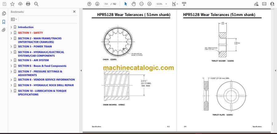
Model: MD5125 Hydraulic Track Drill

Type of Document: Service Manual

Categories: ,

$ 50

Share:

Cat MD5125 Hydraulic Track Drill Service Manual

Cat MD5125 Hydraulic Track Drill Service Manual

The Cat MD5125 Hydraulic Track Drill is engineered for rapid, consistent drilling with robust hydraulic power. This Service Manual maps the drill’s propulsion motors, cooling system layout, rotary drive assembly, and feed mechanisms. It helps technicians track down heat buildup, inconsistent torque delivery, or unexpected pressure drops during long drilling cycles.

Applications & Use Cases

  • Rebuilding rotary head and spindle components

  • Troubleshooting hydraulic pump performance issues

  • Inspecting track drive systems for uneven wear

  • Diagnosing feed motor hesitation

  • Maintaining cooling loops for high-duty drilling

FAQ
Does the manual include pressure test procedures?
Yes, with detailed testing parameters.

Is it suitable for field repairs?
Yes. It is practical and well-structured for on-site diagnostics.

Safety Note
Block track movement securely before accessing drive components.

📘 Show Index

Cat MD5125 Hydraulic Track Drill Index:

  • Introduction
    • Table of Contents
    • U.S./Metric Conversions
    • Glossary of Terms
    • Component Locations (C-10/11 engine)
    • Component Locations (3306 engine)
  • SECTION 1 – SAFETY
    • Overview of Potential Hazards
    • Safety Instructions
    • Clearances from High Voltage Lines
  • SECTION 2 – MAIN FRAME/TRACKS (INTERTRACTOR CRAWLERS)
    • Track Oscillation Cylinders
      • Removal
      • Installation
    • Track Maintenance
    • Track Tension Adjustment
    • Metric Bolt Torque Specifications
    • Track Assembly
      • Separate Track Chain Assembly
      • Track Link – Repair & Replace
      • Track Shoe (grouser) – Mounting to Track Chain
      • Grouser Bolt Torque (Direct Torque Method)
      • Grouser Bolt Torque (Torque Turn Method)
      • Track Chain & Shoe – Assembly & Installation
    • Final Drive – General Description
      • Removal from Track Frame
      • Installation into Track Frame
      • Final Drive Maintenance
        • Oil Check / Change
        • Final Drive Oil
      • Final Drive Assembly
        • Brake Assembly
        • Towing Procedure – Gear Drive Disconnect
    • Idler Unit
      • General Description
      • Removal and Disassembly
      • Assembly and Installation
    • Track Rollers
      • General Description
      • Removal & Disassembly
      • Track Roller – Assembly
      • Track Roller – Test and Install
    • Support Rollers
      • General Description
      • Removal & Disassembly
  • SECTION 3 – POWER TRAIN
    • Hydraulic Pumps
      • Removal and Installation
    • Pump Drive
      • Funk Pump Drive – Removal (for machines built after May, 1998)
      • Funk Pump Drive Gearbox – Repair
      • Terrell Pump Drive Gearbox – Repair
    • Hydraulic Pump Retrofit Procedure
      • Rexroth Pump Installation
    • Fuel System – Cat 3306 Engine
      • Fuel Tank Maintenance
      • Fuel Filters – Every 250 Hours of Operation
      • Priming the Fuel System
    • Fuel System – Cat C-10 & 11 Engine
      • Fuel Tank Maintenance
      • Fuel Filters – Every 250 Hours of Operation
      • Priming the Fuel System
    • Coolers – 3306 Engine
      • Engine Radiator – Capacity and Service
      • Coolant Specifications
      • Coolers – Removal and Installation
    • Coolers – C-10 & 11Engine
      • Engine Radiator – Capacity and Service
      • Coolant Specifications
      • Coolers – Removal and Installation
  • SECTION 4 – HYDRAULIC/ELECTRICAL SYSTEMS/CAB COMPONENTS
    • Hydraulic System
    • Basic Hydraulic Schematic (Vickers Pump)
    • Basic Hydraulic Schematic (Rexroth Pumps)
    • Basic Hydraulic Schematic (Linde Pumps)
    • Tram Console with Boom Hosing
    • Hydraulic Schematic – Drill Console
    • Hydraulic Schematic – Cab
    • Rod Changer Piping
    • Boom Piping
    • Hydraulic Valves – Maintenance
      • Boom/Feed Pilot Valve
      • Tram Pilot Valve
    • Electrical Arrangement – 3306 Engine
    • D.C. Schematic – Non-Cab (3306 Engine)
    • D.C. Schematic – with Cab (3306 Engine)
    • Wiring Diagram – with Cab (3306 Engine)
    • Wire Number/Color Code Chart (3306 Engine)
    • Wiring Diagram – Boom Control Panel
    • Wiring Diagram – Drill Control Panel
    • Wiring Diagram – Tram Control Panel
    • Wiring Diagram – Instrument Panel (3306 Engine)
    • Air Ride Seat Assembly
    • Electrical Arrangement – C-10 Engine
    • D.C. Schematic with Cab (C-10 & 11 Engine)
    • Wiring Diagram – Instrument Panel (C-10 & 11 Engine)
    • Wiring Diagram with Cab (C-10 & 11 Engine)
    • Electrical Arrangement – C-11 Engine
  • SECTION 5 – AIR SYSTEM
    • Air Receiver Tank
      • Preventive Maintenance
      • Troubleshooting
    • Air System Components
    • Compressor Oil Piping
      • Thermostatic Bypass Valve
    • Air Valve Piping (cab machines)
    • Air Valve Piping (non-cab machines)
    • Compressor Assembly
      • Compressor Unit
      • Drive Coupling – Replacement
      • Air Compressor Drive Motor
        • Variable Displacement Motor Adjustment
    • Detergent Tank Piping
  • SECTION 6 – Boom & Feed Components
    • Boom Lift Cylinder
      • Removal
      • Replace
      • Cylinder Bleeding Procedure and Final Installation:
    • Boom Swing Cylinder
      • Removal
      • Replace
      • Cylinder Bleeding Procedure and Final Installation:
    • Feed Dump Cylinder
      • Removal
      • Replace
      • Cylinder Bleeding Procedure and Final Installation:
    • Feed Swing Cylinder
      • Removal
      • Replace
      • Cylinder Bleeding Procedure and Final Installation:
      • Indexing the Feed Swing Cylinder
    • Feed Extension Cylinder
      • Removal
      • Replace
      • Cylinder Bleeding Procedure and Final Installation:
    • Boom Shim/Wear Pad Replacement
      • Boom Wear Pads – Inspection
      • Feed and Feed Table (early style) – Removal from Boom
      • Feed and Feed Table (late style) – Removal from Boom
      • Inner Boom Tube – Removal
      • Rear Wear Pads and Shims – Installation
      • Front Wear Pads and Shims – Installation
      • Feed and Feed Table – Installation on Boom
      • Boom Wear Pads – Final Inspection
    • HPR2 Hydraulic Rock Drill
      • Removal from Feed
      • Mounting Slide Adjustment
    • Feed Chain Adjustment
    • Traveling Hose Reel Timing
    • Feed Table Wear Pad Adjustment
    • Feed Table Pivot Pin
      • Adjustment and Maintenance
  • SECTION 7 – PRESSURE SETTINGS & ADJUSTMENTS
    • Engine Adjustments – Caterpillar 3306
    • Engine Adjustments – Cat C-10 & 11
    • Brake Valve Adjustments
    • Tram System
      • Counterbalance Valve
      • Tram Circuit
      • Joystick Adjustment
    • Boom Joystick Adjustments
    • Feed/Boom Valve Adjustment
    • Main Pump Adjustments (Vickers PVD45)
    • Main Pump Adjustments (Rexroth A11VLO)
    • Main Pump Adjustments (Linde HPR105)
    • Rotation Pump Circuit
    • Drill & Feed Valve Adjustments
    • Collaring Circuit Adjustment (Older Models)
    • Collaring Circuit Adjustment (Late Models)
    • Anti-Jam / Collaring Circuit
    • Reverse Percussion Option
    • Dust Collector Assembly
      • Function of Dust Collector
      • Initial Start-up and Tuning
      • Dust Collector Valve – Adjustment
      • Air Pressure Regulator – Adjustment
      • Timer – Adjustment
      • Fan Speed Adjustment
      • Filter Elements
      • Operational Variables
      • Fine Tuning
      • Manometer Setup Instructions
      • Timer Installation
      • Control Circuit
      • Fan Removal and Installation
      • Troubleshooting Hints
    • Centralizer Adjustment
    • Vertical Indicator
    • Rod Changer Valve
    • 3 Bank Valve – Cab/Drill Console
    • Coupling Grease System
      • Adjustments
      • Daily Maintenance
      • Air Pressure Regulator
      • Filter Assembly
      • Lubricator Assembly
      • 3-Way Air Valve
      • Air Powered Grease Pump
    • Drill Backpressure Valve
  • SECTION 8 – VENDOR SERVICE INFORMATION
    • Index to Service Information
    • Bonfiglioli
    • Char-Lynn / H Series
    • Char-Lynn 2000 Series
    • Fairfield / CT26C
    • Fairfield S1A Final Drive
    • General Engineering
    • Lincoln / 82716 – Series “F”
    • Lincoln / 94424 – Series “A” Electric Grease Pump
    • Rexroth / A2FM90
    • Rexroth / A6VM107
    • Rexroth / A11VLO130
    • Rexroth / A4FM28
    • Sundstrand/Series 51
    • Texas Hydraulics
      • H Head
      • N Head
      • Z Head
      • K Head
      • M Head
      • Z Piston
      • H & K Piston
      • M Piston
      • N Piston
    • Vickers / PVE19L
    • Linde / HPR105
  • SECTION 9 – HYDRAULIC ROCK DRILL REPAIR
    • Hydraulic Rock Drill Service Manual
  • SECTION 10 – LUBRICATION & TORQUE SPECIFICATIONS
    • Hydraulic Oils for Percussion Drills
    • Lubrication and Inspection
    • Engine Oil
    • Preventive Maintenance Chart
    • Bolt Maintenance
    • Bolt Torque Specifications
    • Maintenance Record

Terex

Latest Product

0
    0
    Your Cart
    Your cart is emptyReturn to Shop