Cat MD6420 Rotary Blasthole Drill Service Manual (91-A13-050) (SN 2U67X68)
Out on a mine bench or quarry shot pattern, that MD6420 lives in dust, vibration, and long cold starts, just drilling holes all day. This service manual is about tracing faults step by step so you fix what’s actually bad—hydraulics, electrics, air system, mast and rotation—without just throwing parts at it. Say the rotary head’s losing torque: the book walks you through how to check pressures, verify sensors, inspect wiring, and test valves in order, so you don’t tear into the head before you’ve ruled out a simple control issue.
Applications & Use Cases
- Trace a no-rotation or no-feed complaint by following the hydraulic and electrical sequences, isolating whether it’s a pump, valve, or control signal.
- Check and verify air system problems—weak flushing air, water in the lines—before you call the compressor bad.
- Inspect and align the mast, carriage, and drill string components so you reduce binding, crooked holes, and premature wear.
- Route hoses and cables correctly after a repair, using the diagrams to avoid chafing and future shorts.
- Bleed hydraulic circuits properly after component changes so you don’t chase phantom cavitation issues.
FAQ
Q: Is this a searchable PDF or just scanned pages?
A: It’s typically a searchable PDF, so you can jump to systems, trace schematics, and find tests quickly.
Q: Can I print just the sections I need for the jobsite?
A: Yeah, you can usually print individual sections; most guys keep the dirty pages in a binder on the service truck.
Safety Note
Lock out and tag out all energy sources and bleed stored pressure before you put your hands anywhere near moving drill components.
Cat MD6420 Rotary Blasthole Drill Index:
- X68 Service Manual
- Parts Ordering and Product Support
- Safety Information
- Contents
- General Locator
- General Locator Left View
- General Locator Right View
- General Locator (cont.)
- Section 1 Safety
- Contents
- Safety
- Overview of Potential Hazards
- Noise
- Personal Protective Equipment
- Electrical Contact
- Contaminated Air
- Moving and Rotating Parts
- High Pressure Air or Fluid
- Before Operation
- During Operation
- Maintenance
- Equipment Transfer
- Safety Locator Front View
- Safety Locator Side Views
- Safety Locator Top View
- Safety Locator Panel Views
- Notes
- Section 2 Operators Cab / Controls
- Contents
- Graphic Symbol Legend
- Warning Decals
- Operator Control and Instrument Panels
- Switch Panel
- System Pressure Gauge Panel
- Switches / Diagnostic / Control Panel Circuit
- Cab Heater
- Cab Heater Fault Isolation
- Machine Stability
- New Machine Procedure
- General Maintenance Checks While Tramming
- Roller Locations
- Temperature and Condition Record Chart for Walking
- Propelling the Machine
- Stability Limits
- MD6420 Transient Stability Limits
- Air Conditioner
- T8 Series Split System Air Conditioning
- Section �1.0 Technical Data and Control Settings
- Section 2.0 Installation and Commissioning
- Section 3.0 �Routine Maintenance Procedures
- Section 4.0 Fault Diagnosis
- Section �5.0 Reference Drawings
- Section 3 Main Frame Crawlers
- Contents
- Main Frame Repair – General
- Weld Inspection Schedule
- Levelling Jacks
- Levelling Jack Cylinder
- Levelling Jacks
- Limit Switch
- Levelling Jack Cylinders
- Mast Elevating Cylinders
- Internal Counterbalance Valve
- Crawler Assembly
- Parts List
- Tramming
- Maintenance checks for Tramming
- New Machine Procedure
- General Maintenance Checks While Tramming
- Roller Locations
- Temperature and Condition Record Chart for Walking
- Metric Bolt Torque Specifications
- Metric Bolt Torque Specifications
- Track Tension Adjustment
- Before Operating the Machine
- Track Assembly
- Idler Unit Description
- Hydraulic Tensioner
- Nitrogen Tensioner
- Nitrogen Tensioner – Filling Instructions
- Nitrogen Tensioner – Pressure Check
- Nitrogen Tensioner – Pressure Release
- Track Chain
- Track Link
- Track Link Position
- Track Shoe – Mounting to Track Chain
- Track Shoe Bolt Torque (Direct Torque Method)
- Track Shoe Bolt Torque (Torque Turn Method)
- Track Chain and Shoe Installation
- Track Chain with Shoes
- Track Chain and Shoe – Assembly and Installation
- Final Drive Unit
- Removal from Track Frame
- Installation into Track Frame
- Final Drive Maintenance
- Final Drive Oil
- F100 Final Drive Assembly
- Parking Brake – Description
- Final Drive – Disconnect and Parking Brake
- Towing Procedure – Gear Drive Disconnect
- Parking Brake – Description
- Parking Brake – Removal and Installation
- General Description
- General Recommendations for Disassembly and Assembly Operations
- Technical Features
- Sealing Compounds and Adhesives
- Filling and Checks
- Service Schedule
- Tightening Torques
- Lubrication / Greasing – Grades and Application Range
- General Checks
- �Disassembly and Assembly Operations
- Troubleshooting
- Idler Unit
- Idler Unit – Removal
- Track and Support Rollers
- Track Roller – Removal and Disassembly
- Support Roller – Removal and Disassembly
- Track and Support Roller – Assembly
- Track and Support Roller – Test and Install
- Track and Sprocket Inspection
- Track Inspection and Wear Limit Guide
- Sprocket Wear Patterns
- Auxiliary Crane
- Hydraulic Crane – Rear Deck Crane Palfinger PC1500
- Rear Deck Crane Palfinger PC1500 Service information
- Checking Bolted Connections
- Maintenance Chart
- Lubrication
- Hydraulic Fluids
- Oil Change / Oil Maintenance
- Cleaning Agents and Equipment
- Repairing Paint Damage
- Removal From Service and Disposal
- Section 4 Engine / Drive Train / Compressor
- Contents
- Power Group Locator
- Test Point Locator
- Test Point Locator
- Engine
- QST30 Electric Fuel Supply System
- Construction
- Electric Fuel Supply Pumps
- Combo Fuel Filter Head and Pump Manifold
- FS1006 Fuel Filter with Water Separator
- Fuel Manifold with Integrated FSO Valve
- Fuel Connections
- Pre-filters
- Wiring with EFS Power Relay
- Pressure and Temperature Sensors
- Operation
- QST30 Electric Fuel Supply System Flow Diagram
- QST30 Electric Fuel Supply System Detail
- Oil Reserve Systems
- LED Monitor Readings
- Adjustment of Running Oil Level
- Wiring Diagram – Oil Reserve Basic Circuit
- Oil Pressure Switch
- Oil Reserve System
- Troubleshooting
- Maintenance
- Engine and Compressor Air Cleaners
- Engine and Compressor Air Cleaner Service Assembly
- Engine and Compressor Air Cleaner Service
- Flexible Drive Coupling
- Flexible Drive Coupling Service
- Pump Drive
- Pump Drive Assembly – Removal and Replacement
- Pump Drive Gearbox
- Pump Drive Gearbox – Repair
- Pump Drive Gear Box Input Shaft Assembly
- Hydraulic Pumps
- Hydraulic Pumps – Removal and Replacement
- Compressor Installation
- Compressor Installation
- Compressor Drive Coupling
- Compressor Alignment
- Mounting Instructions for Arcusaflex™ Flywheel Couplings
- Taper-Loc Bushing Installation – Model AC-T5.SN. F2. V1. 3535
- Tightening Torques for Arcusaflex™ Flywheel Couplings
- Compressor Shaft Seal
- Low Pressure Compressor
- Compressor Inlet Valve Control System
- Inlet Valve
- Compressor Regulation
- Relieving Regulators
- Reducing Regulators
- System Blowdown Valve
- Running Blowdown Valve
- Running Blowdown Maintenance
- Compressor Air and Oil Circuits – 2000cfm @ 100psi
- Compressor Air Circuit Parts List
- Compressor Air Circuit Legend
- Compressor Control Set-up Vented Poppet Inlet – Shutdown
- Compressor Control Set-up Vented Poppet Inlet – Initial Start-up Below 50psi
- Compressor Control Set-up Vented Poppet Inlet – Initial Start-up Above 50psi
- Compressor Control Set-up Vented Poppet Inlet – Run Unloaded
- Compressor Control Set-up Vented Poppet Inlet – Drilling
- Compressor Control Set-up Vented Poppet Inlet – Shutting Down
- Operation
- Compressor Maintenance
- Discharge Check Valve
- Compressor Receiver Tank Assembly
- Separator Elements
- Separator Elements – Remove and Replace
- Scavenge Line
- Compressor Discharge Temperature Gauge, Switch and Sender
- Minimum Pressure Valve
- Minimum Pressure / Check Valve Maintenance
- Thermal Bypass Valve
- Thermal Bypass Valve Maintenance
- Compressor Fluid Filter
- Changing Filter Elements
- Oil stop valve
- Troubleshooting
- Coolers
- Hydraulic Oil / Radiator Cooler Assembly
- Compressor Oil Cooler
- Engine Cooler / Radiator
- Aluminium Tube Air to Oil Cooler
- Aluminium Tube Air to Oil Cooler – Standard Parts
- Removal and Replacement
- Internal Cleaning
- Radiator Cooler
- Typical Radiator Core – Standard Parts
- Cleaning
- Tube Removal
- Seal Installation
- Lubricating Seals and Tube Ends
- Tube Installation
- Section 5 Dust Control System
- Contents
- Dust Control System
- Water Injection
- Water Injection Pump
- Water Injection Relief Valve
- Water Injection Control
- Water Injection Basic Circuit
- Water Pump
- Water Injection Pump Assembly
- Replacing Piston Cup Seals
- Replacing Suction and Discharge Valves
- Replacing Power End Bearings
- Servicing the Wrist Pin Bearings
- Fastener Torque Requirements
- Recommended Lubricants
- Water Pump Motor Repair
- Water Injection Hydraulic Control Valve Repair
- Water Pump Drive Coupling
- Level and Flow Transducer
- Section 6 Mast / Rotary Drive / Pipe Rack
- Contents
- Mast Weldment
- Weld Inspection Schedule
- Mast Assembly and Installation
- Mast Weldment
- Mast / Drill Without Mast
- Mast Assembly
- Hoist / Pulldown Cylinder
- Hoist / Pulldown Cylinder and Parts List
- Removal from Mast Assembly
- Repair
- Adjustment
- Replacement
- Wire Rope
- Rotary Drive
- Rotary Head Guide Alignment
- Rotary Head – Drive System
- Removal from Mast
- Rotary Drive Gearbox
- Rotary Drive Gearbox Item Listing
- Rotary Drive Gearbox – Repair
- Rotary Head Bull Shaft Bearing Nut
- Manufacturers Recommendations – Blast Hole Drilling Consumables
- Air Swivel
- Deck Wrench
- H.O.B.O Wrench
- Breakout System – H.O.B.O
- Optional Hydraulic Operated Bit Basket – H.O.B.B
- Pipe Positioner
- Carousel Pipe Rack
- Rod Handling – Carousal Indexing
- Pipe Rack Assembly
- General Information
- Pipe Rack Bearings – Removal
- Pipe Rack Components – Inspection
- Pipe Rack – Assembly and Installation
- Pipe Rack Roller – Remove and Replace
- Pipe Rack Roller – Disassembly and Assembly
- Top Sub Saver (Optional)
- Section 7 Hydraulic Systems
- Contents
- Hydraulic Symbols
- Hydraulic Tank
- Return hydraulic filters
- Main Hydraulic Pumps
- Right Track / Pulldown, Left Track / Rotation Pumps
- Hydraulic Piston Pumps – Removal and Replacement
- Main Pumps
- EP (24V DC) Control
- Linde HPV-02 Variable Displacement Pump
- Operational Parameters
- Linde HPV-02 Pump Schematic
- Controls
- Dimensions
- Setting Linde HPV-02 Main pumps – Neutral Setting
- Setting Linde HPV-02 Main pumps – Pressure Settings
- Setting Linde HPV-02 Main pumps – Pre-setup Checks
- Main Pumps Linde HPV-02
- Break Test Procedure
- Charge Circuit
- Charge Pressure, High Pressure, P.O.R and Zero Position settings
- Charge Filter
- Changing Filter Elements
- Main Pumps Circuit
- Main Return and Case Drain Filter
- Routine Maintenance
- Loop Filters
- Loop Filter cross section
- Filter Assembly Loop
- Changing Filter Elements
- Rotation Circuit
- Rotary Head
- Rotary Head Speed Proximity Switch
- Rotary Drive Gearbox Motor
- Rotary Drive Gearbox Motor – Test and Repair
- Rotary Gearbox Rotation Motor
- Shaft Seal Replacement
- Troubleshooting
- Tram Circuit
- Diverter Valve
- Left Track / Rotation Pump
- Basic Left Track / Rotation Pump
- Right Track / Pulldown and Hoist Circuit
- Basic Right Track / Pulldown and Hoist
- Pulldown and Hoist Circuit
- Hoist / Pulldown Cylinder Counterbalance Valve
- Counterbalance Valves
- Counterbalance Valve Adjustments
- Auxiliary Pump Circuit
- Auxiliary Pump Circuit
- Spools
- Electro – Hydraulic Kit (24V DC)
- Auxiliary Pump Operation
- Jack Control and Mast Elevating Circuit
- Jack Control and Mast Elevating Circuit
- Jack Control and Mast Elevating Circuit
- Levelling Jack Cylinders
- Jack Leg Cylinder
- Counterbalance Valve Test Procedure
- Mast Elevating Cylinders
- Internal Counterbalance Valve
- Internal Counterbalance Valve Test Procedure
- Hydraulic Operated Breakout Wrench
- Operation
- Setting of H.O.B.O Sequence Valves
- Cooler Fan Circuit
- Hydraulic cooler – Thermal valve
- Basic Cooler Fan Circuit
- Cooler Fan Motor
- Cooler Fan Motor Assembly
- Hydraulic Motor
- Water Pump Motor
- Water Pump Motor Repair Information
- Shaft Seal Repair
- Hydraulic Cylinder Repair
- General Information
- H Head
- N Head
- Z Head
- Z Head (Two Piece)
- K Head
- M Head
- Z Piston
- Z Piston (Threaded)
- H and K Piston
- M Piston
- N Piston
- Section 8 Electrical Components
- Contents
- Electrical Locator
- Electrical Component Location
- Jump Starting
- Batteries
- Welding Precautions
- Electrical Components
- EP Levers
- Joystick Adjustments
- Important Information
- PLC
- Touchscreen
- Laser Depth System
- Start Up and Shutdown
- Hydraulic Function Enable
- Alarms
- Solenoid Control
- Auto Lube
- Gauges
- Level Switches
- Dust Suppression
- Acknowledgements
- Disclaimers
- Section 9 Lubrication & Preventive Maintenance
- Contents
- Central Lube System
- Auto Lube Basic Operation
- Central Lube Tank Assembly
- Auto Lube Grease Pump
- Auto Lube Tube Pump
- Graco Vent Valve
- Basic Operating Principles of Auto Lube Injectors
- SL-V and SL-V XL Injectors
- SL-1 and SL-11 Injectors
- SL-32 Injectors
- Typical Grease System Circuit
- First 50 Hour Service
- Lube Faults / Operation
- Auto Lube Timer
- Lube Pressure Screen
- Air Service Units
- Air Line Oiler
- Soft Start Dump Valve
- Air Service Unit
- Pipe Thread Lubricator
- Air Operated Pipe Thread Pump
- Filter Locator
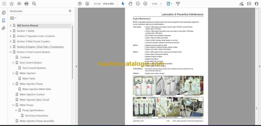
- Lubrication & Preventive Maintenance
- General Lubrication
- Equipment Lubrication
- Care of Lubrication Points
- Safety
- Track Gear
- Engine Maintenance
- Air Cleaners
- Air Filter Elements
- Alternator Maintenance
- Pump Drive and Drive Shaft Maintenance
- Compressor Maintenance
- Cooler Packs
- A-frame and Pivot Point Maintenance
- Pull Down and Hoist Ropes and Sheaves Maintenance
- Rotary Head Maintenance
- Hydraulic System Maintenance
- Hydraulic Maintenance
- Water Pump Maintenance
- Cab maintenance
- Air Conditioner Maintenance
- Battery Maintenance
- Lubrication System Maintenance
- Fire Suppression Maintenance
- Lubrication and Preventive Maintenance
- Drill Folding Stairway – Inspection Requirements
- Weld Inspection Schedule
- Weld Inspection Schedule SK Series
- Track and Sprocket Inspection
- Track Inspection and Wear Limit Guide
- Sprocket Wear Patterns
- Lubrication Recommendations
- Lubrication Recommendations
- Lubrication and Maintenance Chart – 250hr
- Lubrication and Maintenance Chart – 500hr
- Lubrication and Maintenance Chart – 1000hr
- Lubrication and Maintenance Chart – 2000hr
- Lubricant Specifications
- Lubricating Grease
- Gear Lubricant
- Scheduled Oil Sampling Analysis
- Torque Values
- SAE Recommended Torque Values
- Externally Threaded SAE – ASTM Fasteners
- Torque Values
Caterpillar


