$ 0
0
$ 0
0

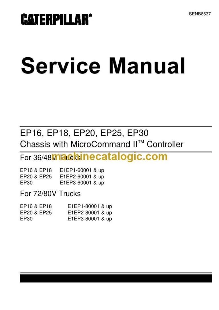
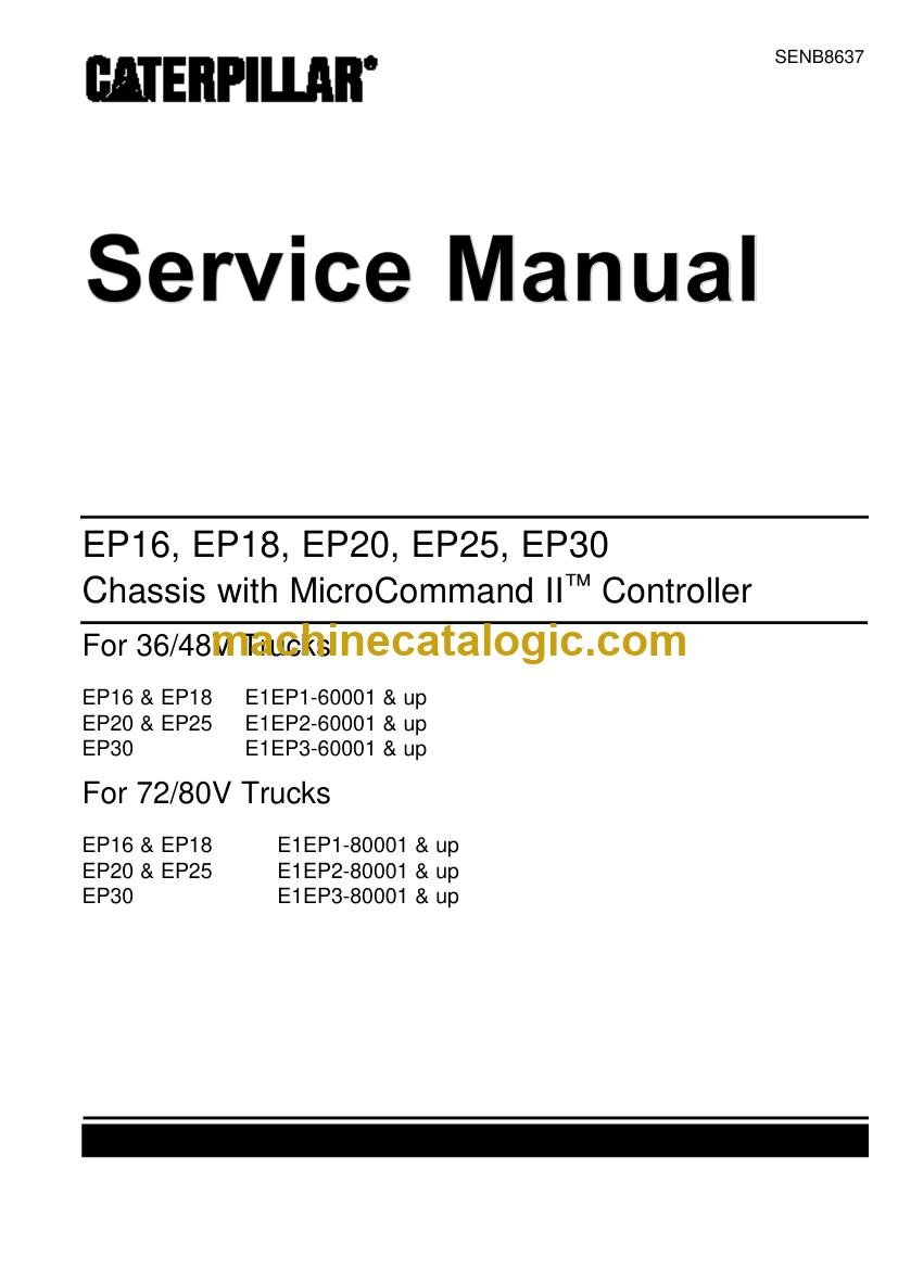
Caterpillar N Range Forklift Service Manual (SENB8637)

Format: PDF (Printable Document)

File Language: English

File Pages: 6704

File Size: 320.18 MB (Speed Download Link)

File Count: 23 PDF files

Brand: Caterpillar

Model: N Range

Equipment Type: Forklift

Book No: SENB8637

Manuals Included: 2 separate publications

Type of Document: Service Manual

Categories: ,

$ 45

Share:

Caterpillar N Range Forklift Service Manual (SENB8637)

These Cat EP trucks are electric counterbalanced forklifts used to move and stack loads around a warehouse or plant. I reach for this type of service manual when a truck has a fault and the repair has to be done in-house, often during a short weekend window. It gives the maintenance tech the service procedures and specifications needed to troubleshoot, adjust, and repair the truck safely.

What this manual helps you do

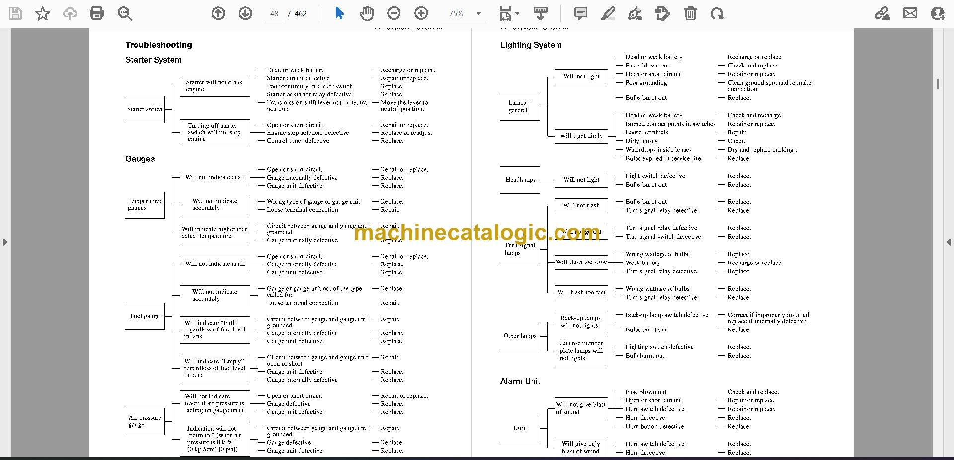
  • Trace electrical faults through the truck wiring and controls.
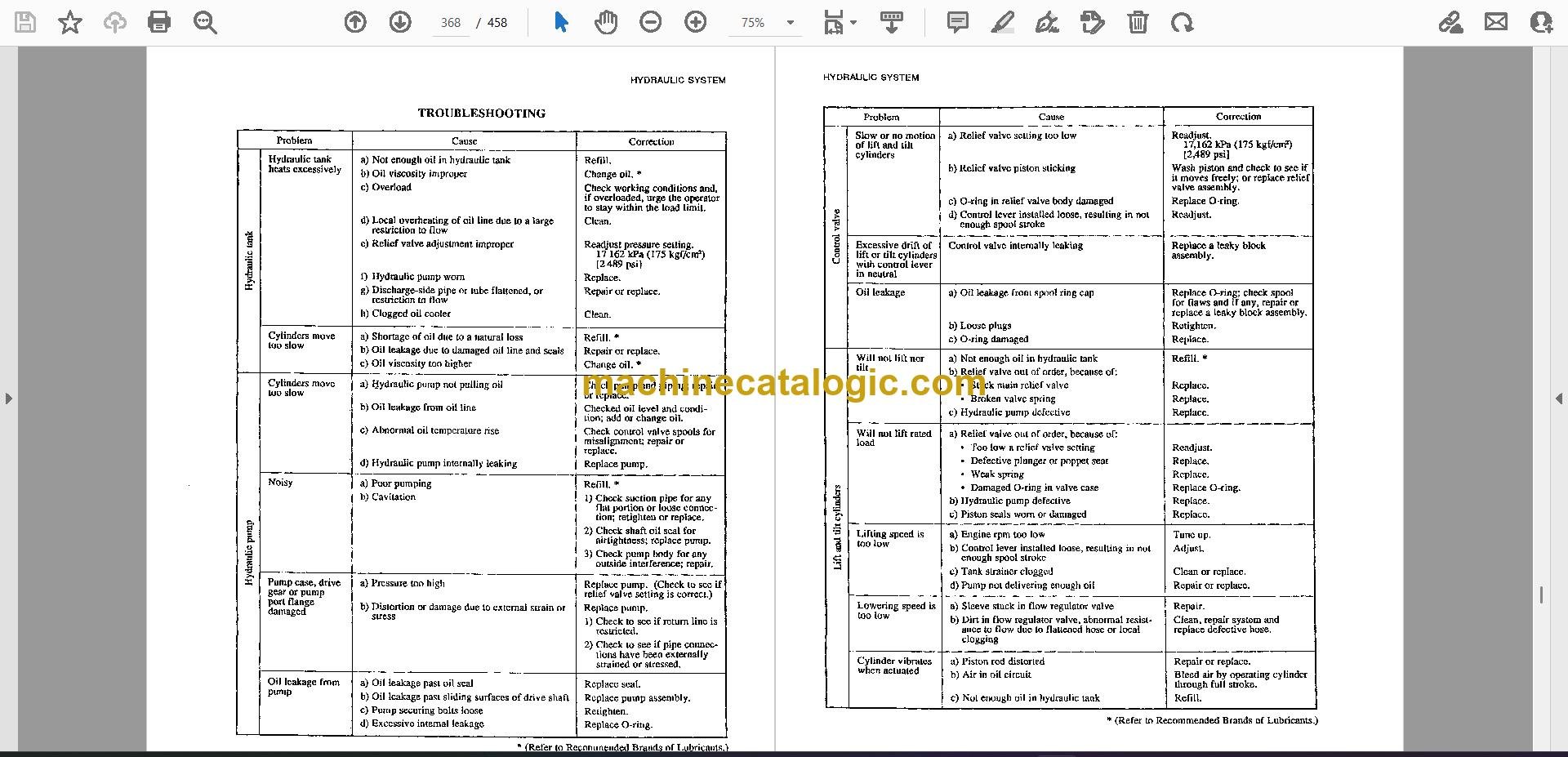
  • Diagnose traction motor, controller, brake, steering, and hydraulic problems.
  • Follow service procedures for the power train, axles, mast, forks, and hydraulic system.
  • Adjust and verify operating systems using the listed service data.
  • Rebuild or replace major truck components with the correct removal and installation sequence.

Who this is for

This suits a plant maintenance technician, warehouse maintenance tech, dealer technician, independent forklift shop, or rental fleet mechanic working on Cat electric counterbalanced trucks. The operator handbook and parts catalog are companion volumes also available, while this is the workshop repair manual.

FAQ

Q: What do I receive?

A: You receive 23 PDF files containing 6,704 pages, split by section. The download includes two separate Cat publications, so you get the manual set rather than one single booklet, with sections arranged for printing or viewing on screen.

Q: Does it fit my truck?

A: Yes, if the nameplate shows EP16, EP18, EP20, EP25, or EP30. Those are the Cat models covered by this publication.

Q: How does it fit the repair job?

A: This is the service manual for workshop-level diagnosis and repair of the electric truck chassis, including electrical, hydraulic, drive, axle, brake, steering, mast, and fork work. It is the book to use when the truck is out of warranty and your shop is handling the repair.

If your Cat truck matches one of those EP models, this set gives you the repair procedures and service data to take the job from fault finding through component repair and return to service.

Models covered by this manual

Caterpillar publication SENB8637 is the factory service manual for the N Range. The cover also lists EP16,, EP18,, EP20,, EP25,, EP30, EP16, EP18, EP20, EP25. Check the model and serial number on your data plate before ordering.

📘 Show Index

Table of Contents:

  • Caterpillar Forklift N Range 99789 65110 SM K21 K25 ENGI Service Manuals
    • How to use this manual
      • Description
      • Definition of Terms
      • Definition of Units
      • Description
    • Precautions for safety and quality
      • Reduction of Risk Operation
      • Correct Operation
      • Precautions for Radio Equipment Installation
    • Precautions
      • Precautions in Draining Engine Coolant
      • Precautions for Disconnecting Fuel Piping
      • Precautions for Removing and Disassembling
      • Precautions for Inspection, Correction, and Replacement
      • Precautions for Assembly and Installation
      • Parts Requiring Angle Tightening
      • Caution for Use of Power Tools
      • Precautions for Liquid Gasket Application
    • Tightening torque
      • Standard Bolt Tightening Torque
      • Engine Part Tightening Torque
    • Special Service Tools
    • Engine outside drawings
    • Standard and repair limit
    • Trouble diagnosis
      • Engine Adjustment
      • Engine LPG Fuel System
    • Engine maintenance
      • Specifications
      • Tightening Torque
      • Maintenance Schedule
      • Oil and Grease, and Capacity
      • On Board Inspection and Service
    • Specifications
    • Tightening torque
    • Trouble diagnosis
    • ENGINE INSPECTION AND ADJUSTMENT
      • Engine Body Related
      • Ignition and Fuel Systems
    • SERVICE DATA AND SPECIFICATIONS (SDS)
      • Electronic Control System Specifications
    • Precautions
      • Precautions for Draining Engine Coolant
      • Precautions for Disconnecting Fuel Piping
      • Precautions for Removing and Disassembling
      • Precautions for Inspection, Correction, and Replacement
      • Precautions for Assembly and Installation
      • Parts Requiring Angle Tightening
      • Caution for Use of Power Tools
      • Precautions for Liquid Gasket Application
    • Engine outside drawings
    • Adjustment value
    • Tightening torque
      • Standard Bolt Tightening Torque
      • Engine Part Tightening Torque
    • Trouble diagnosis
    • Special Service Tools
    • Removal and installation of engine
      • Removal
      • Installation
      • Inspection
    • Engine service
      • Engine Disassembly
      • Inspection and Correction
      • Engine Assembly
    • Precautions
      • General precautions for service operations
    • Preparation
      • Service Tools
    • Description
    • Basic inspection
      • Inspection of Idle Speed, Ignition Timing, and Air-fuel Ratio
      • Throttle Valve Closed Position Learning and Idle Air Volume Learning
      • Accelerator Pedal Released Position Learning
      • Fuel pressure inspection
    • Trouble Diagnosis
      • How to Proceed with Trouble Diagnosis
      • Diagnosis Chart by Symptom
      • Component Parts Location
      • ECM Component
      • Circuit Diagram
      • ECM Terminal Layout
      • ECM Input/Output Signal Specifications
      • Service Tool (ST)
      • Self-Diagnosis Function (without ST)
      • ST Reference Value in Data Monitor
      • Fail-Safe Function
    • Power supply and ground system
      • ECM Input/Output Signal Specifications
      • Circuit Diagram
    • Crankshaft position sensor (POS) system
      • ECM Input/Output Signal Specifications
      • Circuit Diagram
      • Component Parts Inspection
    • Camshaft position sensor (PHASE) system
      • ECM Input/Output Signal Specifications
      • Circuit Diagram
      • Component Parts Inspection
    • Mass air flow sensor system
      • ST Data Monitor Display
      • ECM Input/Output Signal Specifications
      • Circuit Diagram
      • Component Parts Inspection
    • Engine coolant temperature sensor system
      • ST Data Monitor Display
      • ECM Input/Output Signal Specifications
      • Circuit Diagram
      • Component Parts Inspection
    • Heated oxygen sensor system
      • ST Data Monitor Display
      • ECM Input/Output Signal Specifications
      • Circuit Diagram
    • Throttle position sensor system
      • ST Data Monitor Display
      • ECM Input/Output Signal Specifications
      • Circuit Diagram
      • Component Parts Inspection
    • Accelerator pedal position sensor system
      • ST Data Monitor Display
      • ECM Input/Output Signal Specifications
      • Circuit Diagram
      • Component Parts Inspection
    • Intake air temperature sensor
      • ST Data Monitor Display
      • ECM Input/Output Signal Specifications
      • Circuit Diagram
      • Component Parts Inspection
    • PNP switch system
      • ST Data Monitor Display
      • ECM Input/Output Signal Specifications
      • Circuit Diagram
    • Stop lamp switch system
      • ST Data Monitor Display
      • ECM Input/Output Signal Specifications
      • Circuit Diagram
      • Component Parts Inspection
    • Electric load switch system
      • ST Data Monitor Display
      • ECM Input/Output Signal Specifications
      • Circuit Diagram
    • CAN communication system
      • ECM Input/Output Signal Specifications
      • Circuit Diagram
    • Ignition system
      • ST Data Monitor Display
      • ECM Input/Output Signal Specifications
      • Circuit Diagram
      • Component Parts Inspection
    • Fuel injector system
      • ST Data Monitor Display
      • ECM Input/Output Signal Specifications
      • Circuit Diagram
      • Component Parts Inspection
    • Fuel pump system
      • ST Data Monitor Display
      • ECM Input/Output Signal Specifications
      • Circuit Diagram
      • Component Parts Inspection
    • Throttle control motor system
      • ECM Input/Output Signal Specifications
      • Circuit Diagram
      • Component Parts Inspection
    • Heated oxygen sensor heater system
      • ST Data Monitor Display
      • ECM Input/Output Signal Specifications
      • Circuit Diagram
      • Component Parts Inspection
    • PCV gas recirculation device
      • System Diagram
      • Component Parts Inspection
    • Fuel cut function
      • Inspection Procedure
    • Removal and installation of ECM components
      • Removal and Installation of ECM
      • Removal and Installation of Crankshaft Position Sensor (POS)
      • Removal and Installation of Camshaft Position Sensor (PHASE)
      • Removal and Installation of Mass Air Flow Sensor
      • Removal and Installation of Engine Coolant Temperature Sensor.
      • Removal and Installation of Heated Oxygen Sensor (with Heated Oxygen Sensor Heater)
      • Removal and Installation of Throttle Position Sensor (Electric Throttle Control Actuator Assembly)
      • Removal and Installation of Accelerator Pedal Position Sensor (Accelerator Pedal Assembly)
      • Removal and Installation of Intake Air Temperature Sensor (with Mass Air Flow Sensor)
      • Removal and Installation of Neutral Switch (M/T Model)
      • Removal and Installation of Ignition Coil (with Power Transistor)
      • Removal and Installation of Fuel Injector
      • Removal and Installation of Fuel Pump
      • Removal and Installation of Throttle Control Motor (Electric Throttle Control Actuator Assembly)
      • Removal and Installation of LPG Injector Holder
      • Removal and Installation of LPG Injector Drive Unit
    • SERVICE DATA AND SPECIFICATIONS (SDS)
      • Standard, Repair Limit
    • Lubrication system
      • Specifications
      • Adjustment Value
      • Oil Pressure
      • Tightening Torque
      • Trouble Diagnosis
      • Lubrication Schematic Diagram
      • Oil Pump
    • Engine coolant system
      • Specifications
      • Adjustment Value
      • Tightening Torque
      • Trouble Diagnosis
      • Cooling System Configuration
      • Water Pump
      • Thermostat
    • Emission control system (only for electronic controlled type)
    • Unit layout
    • LPG fuel system trouble diagnosis
    • Disassembly and assembly of fuel system
      • Removal and Installation of LPG Injector Drive Unit Connector
      • Removal and Installation of Electronic Control Throttle Assembly
      • Removal and Installation of Gasoline Fuel Injector (Electronic Controlled Gasoline and Combined Use)
      • Injector Holder
    • Vaporizer mechanism and operation
      • Primary (Decompression) Room
      • Description
    • Adjustment value
    • Trouble diagnosis
    • Starter motor
      • Starter Motor Specifications
      • Component Parts Location
      • Overhaul
      • Assembly Inspection
    • Alternator
      • Components of Alternator
      • Disassembly
      • Inspection

Caterpillar Software

Caterpillar PDF Manuals

Related Manuals

0
    0
    Your Cart
    Your cart is emptyReturn to Shop