Format: PDF (Printable Document)
File Language: English
File Pages: 114
File Size: 16.78 MB (Speed Download Link)
Brand: Clark
Model: C20S.U. & C25S.U. -1-436 and Above
Book No: Code 130
Type of Document: Maintenance Manual
$ 40
## Table of Contents
### General Maintenance & Procedures
– Planned Maintenance Procedures
– Alternator Maintenance
– Axle End Lubrication
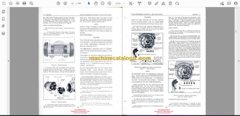
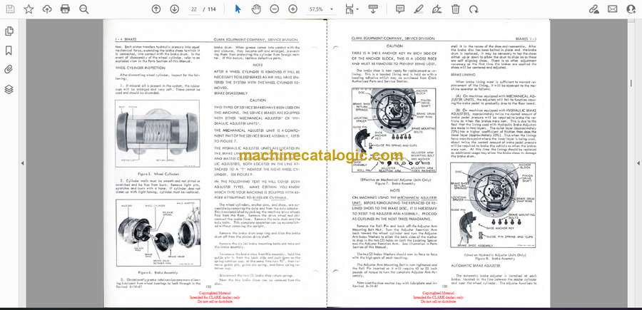
– Brake Adjustment (Parking & Service)
– Brake Bleeding
– Brake Pedal Adjustment
– Carriage Roller Adjustment
– Catalytic Muffler
– Cooling System Maintenance
– Clutch Adjustment
– Differential
– Fuel Pump Tests
– Hydraulic Sump Drain
– Hydraulic System Pressure Check
– Jacking Procedure
– Lift Chain Adjustment
– Lubrication Charts & Key
– Name Plates / Machine Stampings
– Neutral Start Switch
– Safety / Inspection Forms
– Specifications
– Steering Adjustment
– Steering Pressure Check
– Steer Wheel Bearings
– Tilt Cylinder Adjustment
– Towing Instructions
– Transmission
– Tune-Up
– Upright Roller Adjustment
– Upright & Tilt Cylinder Drift Tests
– Wheels & Tires
### Vehicle Components (Alphabetical)
– Accelerator Pedal & Linkage
– Air Cleaner Assembly
– Ammeter Gauge
– Axle Assembly: Drive & Steering
– Battery Cables & Parts
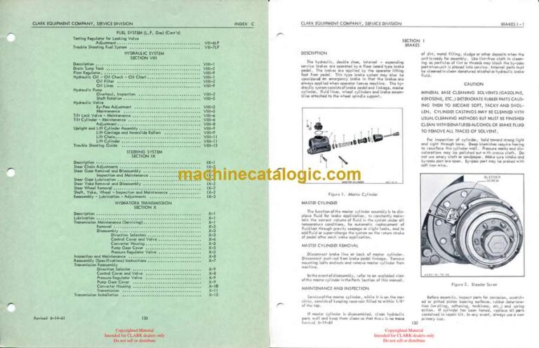
– Brake Assembly: Emergency, Drive Wheel, Master Cylinder, Pedal
– Breather Pipe & Oil Filler Pipe
– Camshaft, Valves, Timing Gear
– Carburetor, Choke Control
– Circuit Wiring
– Clutch Assembly
– Connecting Rods, Bearings
– Control Rods, Shifters
– Cylinder Head, Pistons, Rings
– Dash, Floor Plates, Seats
– Decals & Name Plates
– Differential Assembly & Carrier
– Distributor Assembly
– Drag Link, Drive Tires, Drive Wheels
– Electrical Equipment
– Engine Assembly, Gasket Set
– Exhaust Pipe
– Fan Belt, Blade, Pulley
– Floor Plates
– Fuel Cap, Gauge, Pump, Tank
– Gas Tank Cap & Safety
– Gear Shift Lever, Selector, Governor Assembly
– Hand Brake
– Horn
– Hood, Louvers
– Ignition Switch, Coil
– Intake & Exhaust Manifold
– Motor Mount, Muffler
– Oil Bayonet Gauge, Filter, Gauge, Pump
– Radiator
– Seat
– Shift Lever
– Spark Plugs
– Starter Assembly
– Steering: Axle, Gear, Hand Wheel, Wheels, Tires
– Support: Axle, Gear Bracket
– Tail Pipe, Thermostat
– Timing Gear Cover
– Tires: Drive & Steering
– Transmission
– Undersize Main Rod Bearings
– Valves, Tappets, Voltage Regulator
– Water Pump, Recirculating Hose
– Wheel Brake Cylinder, Drive, Steering
– Wiring Diagram
### Section-Based Instructions
#### Part One – Vehicle Operating Instructions
– Introduction
– Description and Tabulated Data
– Tools and Equipment
#### Part Two – Operating Instructions
– General
– Service Upon Receipt
– Controls and Instruments
– Operation Under Usual/Unusual Conditions
– Demolition to Prevent Enemy Use
#### Part Three – Maintenance Instructions
– General
– Lubrication
– Record of Modifications
– Preventive Maintenance
– Trouble Shooting
– Engine Description & Adjustments
– Clutch & Linkage
– Fuel, Air, Exhaust Systems
– Cooling System
– Ignition & Starting
– Transmission
– Driving & Steering Axles
– Service Brake System
– Hand Brake & Linkage
– Wheels, Bearings, Tires
– Rear Springs & Shackles
– Steering Gear
– Hydraulic System
#### Part Four – Repair Instructions
– General
– Engine, Clutch, Fuel, Cooling, Electrical System
– Transmission
– Axles, Brakes, Wheels, Steering
– Hydraulic System
#### Other Major Sections
– Electrical System
– Engine System
– Fuel System (Standard & L.P. Gas)
– Hydraulic System
– Steering System
– Hydrotork Transmission
– Brake System
– Cooling System
– Differential and Axle Ends
– Hydrotork Drive
