Format: PDF (Printable Document)
File Language: English
File Pages: 95
File Size: 2.10 MB (Speed Download Link)
Brand: Clark
Model: CS15, CS20 Service and
Book No: CS_SPM630A
Type of Document: Parts Manual
$ 40
1. Receipt Inspection …………………………………………………………………………………………………………3
2. Pre-Operation Instructions……………………………………………………………………………………………….3
3. Safety Information………………………………………………………………………………………………………….4
4. Operating Instructions …………………………………………………………………………………………………….5
5. Control System……………………………………………………………………………………………………………..7
6. Battery Discharge Indicator (BDI) – Operation………………………………………………………………………9
6.1 Hourmeter ……………………………………………………………………………………………………………9
6.2 BDI and Hourmeter ………………………………………………………………………………………………10
6.3 BDI w/Lift Interlock……………………………………………………………………………………………….11
7. Drive Unit & Brake ……………………………………………………………………………………………………….12
8. Mast and Carriage ……………………………………………………………………………………………………….13
9. Hydraulic Adjustments ………………………………………………………………………………………………….13
9.1 Lifting Pressure …………………………………………………………………………………………………..13
9.2 Lowering Speed:………………………………………………………………………………………………….13
10. Planned Maintenance …………………………………………………………………………………………………..14
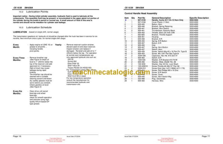
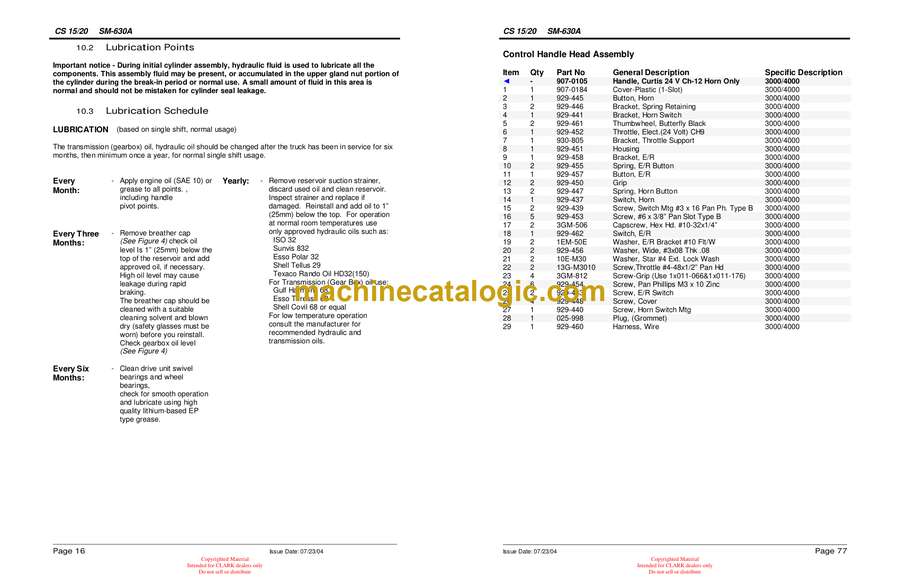
10.1 Lubrication Points ………………………………………………………………………………………………..15
10.2 Lubrication Points ………………………………………………………………………………………………..16
10.3 Lubrication Schedule ……………………………………………………………………………………………16
10.4 Battery Maintenance …………………………………………………………………………………………….17
10.5 Battery Cable Connections …………………………………………………………………………………….18
(for built-in battery / charger pack)
11. Trouble Shooting Guide ………………………………………………………………………………………………..19
12. Heavy Duty Stacker – Parts Listings …………………………………………………………………………………20
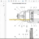
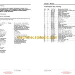
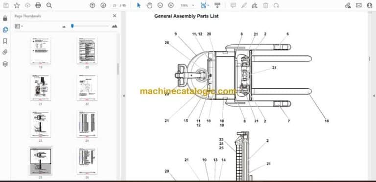
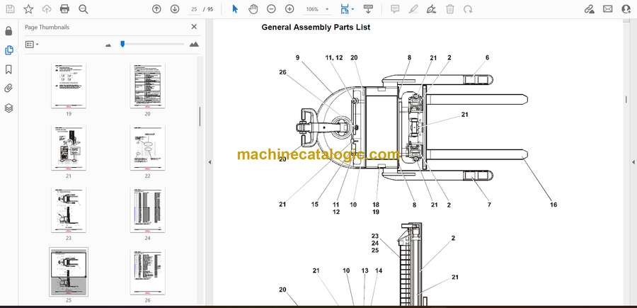
12.1 General Assembly Parts List…………………………………………………………………………………..22
12.2 Mast and Carriage Assembly – Single Stage ………………………………………………………………26
12.2.1 Cylinder Assembly – 3000 Single Stage…………………………………………………………28
12.2.2 Cylinder Assembly – 4000 Single Stage…………………………………………………………30
12.2.3 Crosshead Assembly – Single Stage …………………………………………………………….32
12.2.4 Chain Assembly – Single Stage……………………………………………………………………33
12.3 Mast and Carriage Assembly – 2 Stage …………………………………………………………………….34
12.3.1 Lift Cylinder Assembly – Two Stage………………………………………………………………36
12.3.2 Chain Assembly – 2 Stage………………………………………………………………………….38
12.3.3 Crosshead Assembly – 2 Stage……………………………………………………………………39
12.4 Mast and Carriage Assembly – 2 Stage Full Free ………………………………………………………..40
12.4.1 Lift Cylinder Assembly – 2 Stage 130, 150″ Full Free………………………………………..42
12.4.2 Outboard Cylinder Assembly – 2 Stage 130, 150″ Full Free………………………………..44
12.4.3 Chain Assembly – 2 Stage 130, 150″ Lift Height ………………………………………………46
12.4.4 Crosshead Assembly – 2 Stage 130, 150″ Lift Height………………………………………..47
12.5 Mast and Carriage Assembly – 3 Stage 160, 180″ Lift…………………………………………………..48
12.5.1 Cylinder Assembly – 3 Stage 160, 180″ Lift Height……………………………………………52
12.5.2 Chain Assembly – 3 Stage 160, 180″ Lift Height ………………………………………………54
12.5.3 Crosshead Assembly – 3 Stage 160, 180″ Lift …………………………………………………55
12.6 Mast and Carriage Assembly – 3 Stage 172″ Lift Full Free …………………………………………….56
12.6.1 Chain Assembly – 3 Stage 172″ Lift Full Free ………………………………………………….58
12.6.2 Chain Assembly – 3 Stage 172″ Lift Full Free ………………………………………………….59
12.6.3 Crosshead Assembly – 3 Stage 172″ Lift Full Free……………………………………………60
12.6.4 Lift Cylinder Assembly – 3 Stage 172″ Lift Full Free ………………………………………….62
12.6.5 Outboard Cylinder Assembly – 3 Stage 172″ Lift Full Free………………………………….64
12.7 Left Straddle Assembly …………………………………………………………………………………………66
12.8 Right Straddle Assembly ……………………………………………………………………………………….68
12.9 Right Straddle Assembly ……………………………………………………………………………………….69
12.10 Electric Drive Unit Assembly…………………………………………………………………………………..70
12.11 Drive Unit Assembly – Electrical ………………………………………………………………………………72
12.11.1 Control Handle Assembly ……………………………………………………………………….74
12.11.2 Control Handle Head Assembly ……………………………………………………………….76
12.11.3 Controller Panel Assembly ……………………………………………………………………..78
12.11.4 Drive Unit Wiring Kit ………………………………………………………………………………80
12.11.5 Drive Unit Column Assembly – Mechanical …………………………………………………82
12.11.6 Drive Unit Gearbox Assembly ………………………………………………………………….84
12.11.7 Wiring Kit – Rear Battery Box Plate …………………………………………………………..86
12.12 Hydraulic Layout ………………………………………………………………………………………………….88
13. Wiring/Hydraulic Schematic……………………………………………………………………………………………92
13.1 Mechanical/Hydraulic Lift Control Schematic ……………………………………………………………..92
13.2 Electric/Hydraulic Lift Control Schematic …………………………………………………………………..93
