Format: PDF (Printable Document)
File Language: English
File Pages: 194
File Size: 9.06 MB (Speed Download Link)
Brand: Clark
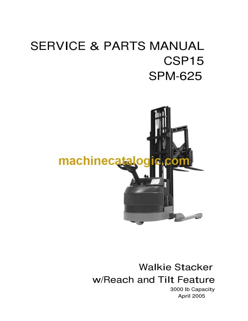
Model: CSP15 Walkie Stacker with Reach and Tilt Feature Service and
Book No: CSP_SPM625A1
Type of Document: Parts Manual
$ 40
1. Receipt Inspection ………………………………………………………………………………………………………………….4
2. Pre-Operation Instructions……………………………………………………………………………………………………….4
3. Safety Information…………………………………………………………………………………………………………………..5
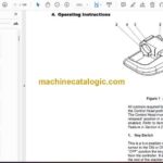
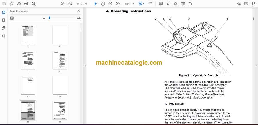
4. Operating Instructions …………………………………………………………………………………………………………….7
4.1 Optional Controls …………………………………………………………………………………………………………11
4.2 Basic Operation …………………………………………………………………………………………………………..12
5. Control System …………………………………………………………………………………………………………………….13
6. Optional Instruments – Operation ……………………………………………………………………………………………15
6.1 Hour Meter ………………………………………………………………………………………………………………….15
6.2 BDI and Hour Meter……………………………………………………………………………………………………..16
6.3 BDI/ Hour Meter w/Lift Lockout………………………………………………………………………………………17
6.4 BDI/ Hour Meter …………………………………………………………………………………………………………..17
7. Drive Unit & Brake ………………………………………………………………………………………………………………..18
8. Mast and Carriage ………………………………………………………………………………………………………………..20
9. Hydraulic Adjustments…………………………………………………………………………………………………………..20
9.1 Lifting Pressure ……………………………………………………………………………………………………………20
9.2 Lowering Speed:………………………………………………………………………………………………………….20
10. Planned Maintenance……………………………………………………………………………………………………………21
10.1 Lubrication Points ………………………………………………………………………………………………………..22
10.2 Lubrication Schedule ……………………………………………………………………………………………………24
10.3 Hydraulic Reservoir Maintenance…………………………………………………………………………………..25
10.4 Battery Maintenance…………………………………………………………………………………………………….26
11. Trouble Shooting Guide…………………………………………………………………………………………………………29
12. Heavy Duty Stacker – Parts Listings………………………………………………………………………………………..30
12.1 General Assembly Parts List …………………………………………………………………………………………32
12.2 Mast and Carriage Assembly – Single Stage……………………………………………………………………36
12.2.1 Reach and Tilt Assembly – Single Stage …………………………………………………………….38
12.2.2 Mast and Carriage Weldment Ass’y – Three Stage ………………………………………………40
12.2.3 Lift Cylinder Assembly – Single Stage ………………………………………………………………..42
12.2.4 Chain Assembly – Single Stage …………………………………………………………………………44
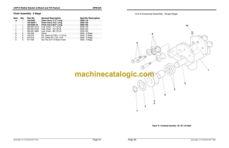
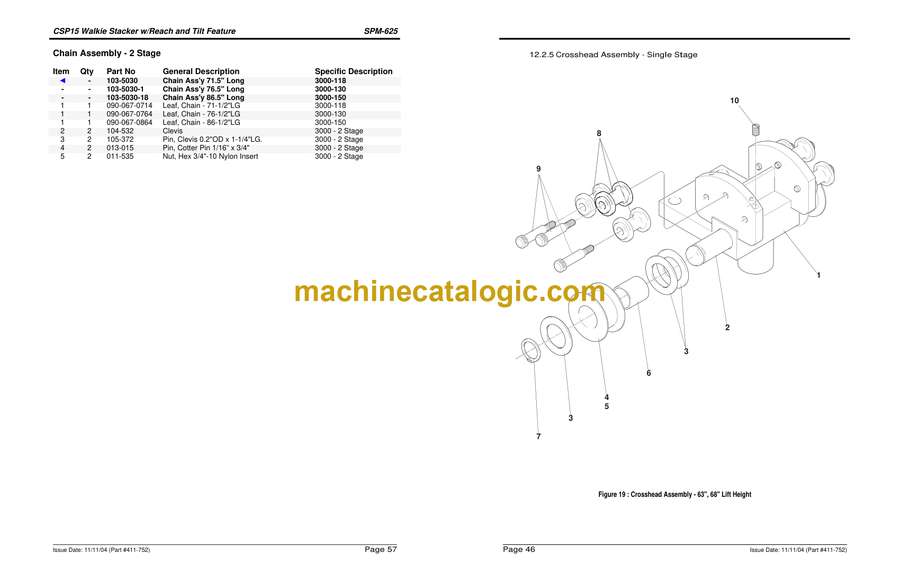
12.2.5 Crosshead Assembly – Single Stage ………………………………………………………………….46
12.3 Mast and Carriage Assembly – 2 Stage…………………………………………………………………………..48
12.3.1 Reach and Tilt Assembly – Two Stage ……………………………………………………………….50
12.3.2 Mast and Carriage Weldment Ass’y – Two Stage…………………………………………………52
12.3.3 Lift Cylinder Assembly – Two Stage……………………………………………………………………54
12.3.4 Chain Assembly – 2 Stage ………………………………………………………………………………..56
12.3.5 Crosshead Assembly – 2 Stage …………………………………………………………………………58
12.4 Mast and Carriage Assembly – 2 Stage Full Free……………………………………………………………..60
12.4.1 Reach and Tilt Assembly – 2 Stage Full Free………………………………………………………62
12.4.2 Mast and Carriage Weldment Ass’y – Three Stage ………………………………………………64
12.4.3 Lift Cylinder Assembly – 2 Stage Full Free ………………………………………………………….66
12.4.4 Outboard Cylinder Assembly – 2 Stage Full Free…………………………………………………68
12.4.5 Chain Assembly – 2 Stage 130″ Lift Height …………………………………………………………70
12.4.6 Crosshead Assembly – 2 Stage 130″ Lift Height ………………………………………………….72
12.5 Mast and Carriage Assembly – 3 Stage 160, 180″ Lift……………………………………………………….74
12.5.1 Mast Chain Assembly – 3 Stage 160. 180 ” Lift Height………………………………………….76
12.5.2 Carriage Chain Assembly – 3 Stage 160. 180 ” Lift Height ……………………………………78
12.5.3 Cylinder Assembly – 3 Stage 160, 180″ Lift Height……………………………………………….80
12.5.4 Reach and Tilt Assembly – 3 Stage ……………………………………………………………………82
12.5.5 Mast and Carriage Weldment Ass’y – Three Stage ………………………………………………84
12.5.6 Crosshead Assembly – Three Stage…………………………………………………………………..86
12.6 Mast and Carriage Assembly – 3 Stage Full Free……………………………………………………………..88
12.6.1 Reach and Tilt Assembly – Three Stage Full Free ……………………………………………….90
12.6.2 Reach/Tilt Sub-Assembly – Three Stage Full free ………………………………………………..92
12.6.3 Mast and Carriage Weldment……………………………………………………………………………94
12.6.4 Reach Cylinder Assembly – Three Stage 172′ Full Free ……………………………………….96
12.6.5 Tilt Cylinders – Three Stage 172′ Full Free………………………………………………………….98
12.6.6 Chain Assembly – Three Stage 172′ Full Free……………………………………………………100
12.6.7 Chain Assembly – Three Stage 172′ Full Free……………………………………………………102
12.6.8 Crosshead Assembly – Three Stage 172′ Full Free…………………………………………….104
12.6.9 Lift Cylinder Assembly – Three Stage 172′ Full Free …………………………………………..106
12.6.10 Outboard Cylinder Assembly – Three Stage 172′ Full Free ……………………………..108
12.7 Left Straddle Assembly……………………………………………………………………………………………….110
12.8 Right Straddle Assembly …………………………………………………………………………………………….112
12.9 Electric Drive Unit Assembly………………………………………………………………………………………..114
12.9.1 Drive Unit Assembly – Electrical ………………………………………………………………………116
12.9.2 Control Handle Assembly ……………………………………………………………………………….118
12.9.3 Control Handle Head Assembly ………………………………………………………………………120
12.9.4 Controller Panel Assembly ……………………………………………………………………………..122
12.9.5 Drive Unit Wiring Kit……………………………………………………………………………………….124
12.9.6 Drive Unit Column Assembly – Mechanical ……………………………………………………….126
12.9.7 Gearbox Assembly ………………………………………………………………………………………..128
12.9.8 Wiring Kit – Rear Battery Box Plate ………………………………………………………………….130
12.10 Hydraulic Layout – Single Stage …………………………………………………………………………………..132
12.10.1 Reach Cylinder Assembly – Single Stage ……………………………………………………..134
12.10.2 Tilt Cylinder Assemblies – Single Stage ………………………………………………………..136
CSP15 Walkie Stacker w/Reach and Tilt Feature SPM-625
Issue Date: 11/11/04 (Part #411-752) Page 3
12.11 Hydraulic Layout – Two Stage………………………………………………………………………………………138
12.11.1 Reach Cylinder Assembly – Two Stage…………………………………………………………140
12.11.2 Tilt Cylinder Assemblies – Two Stage …………………………………………………………..142
12.12 Hydraulic Layout – Two Stage Full Free ………………………………………………………………………..144
12.12.1 Reach Cylinder Assembly – Two Stage…………………………………………………………148
12.12.2 Tilt Cylinder Assemblies – Two Stage …………………………………………………………..150
12.13 Hydraulic Layout – Three Stage……………………………………………………………………………………152
12.13.1 Reach Cylinder Assembly – Three Stage ………………………………………………………154
12.13.2 Tilt Cylinder Assemblies – Three Stage…………………………………………………………156
12.14 Hydraulic Layout – Three Stage Full Free………………………………………………………………………158
12.15 Body Hydraulic Layout – One and Two Stage ………………………………………………………………..160
12.16 Control Valve Assembly………………………………………………………………………………………………162
12.17 Hydraulic Reservoir Assembly……………………………………………………………………………………..164
12.18 Body Hydraulic Layout – Three Stage……………………………………………………………………………166
12.19 Control Valve Assembly………………………………………………………………………………………………168
12.20 Hydraulic Reservoir Assembly……………………………………………………………………………………..170
12.21 Body Hydraulic Layout – Two Stage Full Free ………………………………………………………………..172
12.22 Control Valve Assembly………………………………………………………………………………………………174
12.23 Hydraulic Reservoir Assembly……………………………………………………………………………………..176
12.24 Body Hydraulic Layout – Three Stage Full Free ……………………………………………………………..178
12.25 Control Valve Assembly………………………………………………………………………………………………180
12.26 Relief Valve Assembly ………………………………………………………………………………………………..182
12.27 Hydraulic Reservoir Assembly……………………………………………………………………………………..184
13. Wiring/Hydraulic Schematics………………………………………………………………………………………………..186

