Format: PDF (Printable Document)
File Language: English
File Pages: 902
File Size: 54.83 MB (Speed Download Link)
Brand: Clark
Model: S20, S25, S30, S35 L,G PSI Engine Truck Forklift
Book No: SM1085
Part No: 8146159
Type of Document: Service Manual
$ 40
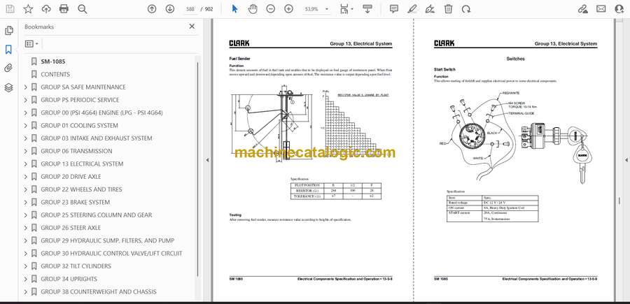
SM-1085
CONTENTS
GROUP SA SAFE MAINTENANCE
Section 1 Safety
Section 2 Lifting, Jacking, and Blocking the Truck
Section 3 Towing
GROUP PS PERIODIC SERVICE
Section 1 Maintenance Schedules
Section 2 The Planned Maintenance Program
GROUP 00 (PSI 4G64) ENGINE (LPG – PSI 4G64)
Section 1 General Information
Section 2 Timing Belt
Section 3 Water Pump
Section 4 Rocker Arms and Camshaft
Section 5 Cylinder Head and Valves
Section 6 Front Case, Silent Shaft and Oil Pan
Section 7 Piston and Connecting Rod
Section 8 Crankshaft and Cylinder Block
Section 9 Engine Compression Test
Section 10 Maintenance
Section 11 LPG Fuel System
Section 12 Gasoline Fuel System
Section 13 Emissions Control System
Section 14 Electrical Section
Section 15 Diagnostic Scan Tool (DST)
Section 16 Engine Wire Harness Repair
Section 17 Diagnostic Trouble Code (DTC)
Section 18 Definitions
GROUP 01 COOLING SYSTEM
Section 1 Cooling System Specifications and Description
Section 2 Cooling System Troubleshooting
Section 3 Cooling System Testing and Maintenance
Section 4 Radiator Removal and Replacemant
GROUP 03 INTAKE AND EXHAUST SYSTEM
Section 1 Intake and Exhaust Systems Specifications and Description
Section 2 Intake System Troubleshooting
Section 3 Intake System Service
Section 4 Exhaust Systems
GROUP 06 TRANSMISSION
Section 1 Transmission Specifications and Description
Section 2 Transmission Troubleshooting
Section 3 Transmission Oil and Filter
Section 4 Transmission Oil Cooler
Section 5 Transmission Overhaul Overview
Section 6 Transmission Overhaul Procedure
Section 7 Transmission Control Valve Overhaul
Section 8 Transmission Removal and Installation
GROUP 13 ELECTRICAL SYSTEM
Section 1 Cautions for working on the electrical system
Section 2 Electrical system Specifications and features
Section 3 Electrical Circuit Diagram & Electrical Parts Arrangement
Section 4 Instrument Pod
Section 5 Electrical Components Specification and Operation
GROUP 20 DRIVE AXLE
Section 1 Drive Axle Specifications and Description
Section 2 Drive Axle Disassembly and Assembly
Section 3 Troubleshooting
GROUP 22 WHEELS AND TIRES
Section 1 Wheels and Tires Specifications and Description
Section 2 Pneumatic Wheels and Tires
GROUP 23 BRAKE SYSTEM
Section 1 Braking / Inching System Specifications and Description
Section 2 Service Brake Troubleshooting
Section 3 Brake/Inching Pedals and Linkages Adjustments
Section 4 Brake Bleeding
Section 5 Brake Valve Service
Section 6 Parking Brake Service
Section 7 Parking Brake Troubleshooting
GROUP 25 STEERING COLUMN AND GEAR
Section 1 Steering System Specifications and Description
Section 2 Steering System Troubleshooting
Section 3 Steering Column and Component Removal and Replacement
Section 4 Steering System Relief Pressure Check and Adjustment
Section 5 Steering Gear Overhaul
GROUP 26 STEER AXLE
Section 1 Steer Axle Specifications and Description
Section 2 Steer Axle Wheel Bearing Maintenance and Adjustment
Section 3 Steer Axle Removal and Replacement
Section 4 Steer Axle Overhaul
Section 5 Steer Cylinder Removal and Replacement
Section 6 Steer Cylinder Overhaul
GROUP 29 HYDRAULIC SUMP, FILTERS, AND PUMP
Section 1 Hydraulic Sump, Filters, and Pump Specifications and Description
Section 2 Main Hydraulic Pump Troubleshooting
Section 3 Hydraulic Filters and Fluid Maintenance and Change
Section 4 Hydraulic Pump Removal and Replacement
Section 5 Hydraulic Pump Overhaul
GROUP 30 HYDRAULIC CONTROL VALVE/LIFT CIRCUIT
Section 1 Hydraulic Control Valve/Lift Circuit Specifications and Description
Section 2 Hydraulic System Schematics
Section 3 Hydraulic System Troubleshooting
Section 4 Hydraulic System Pressure Checks and Adjustments
Section 5 Hydraulic Control Valve Removal and Replacement
Section 6 Hydraulic Control Valve (MCV) Disassembly and Assembly
Section 7 EHL Valve Disassembly and assembly
Section 8 Testing of Hydraulic Valve
GROUP 32 TILT CYLINDERS
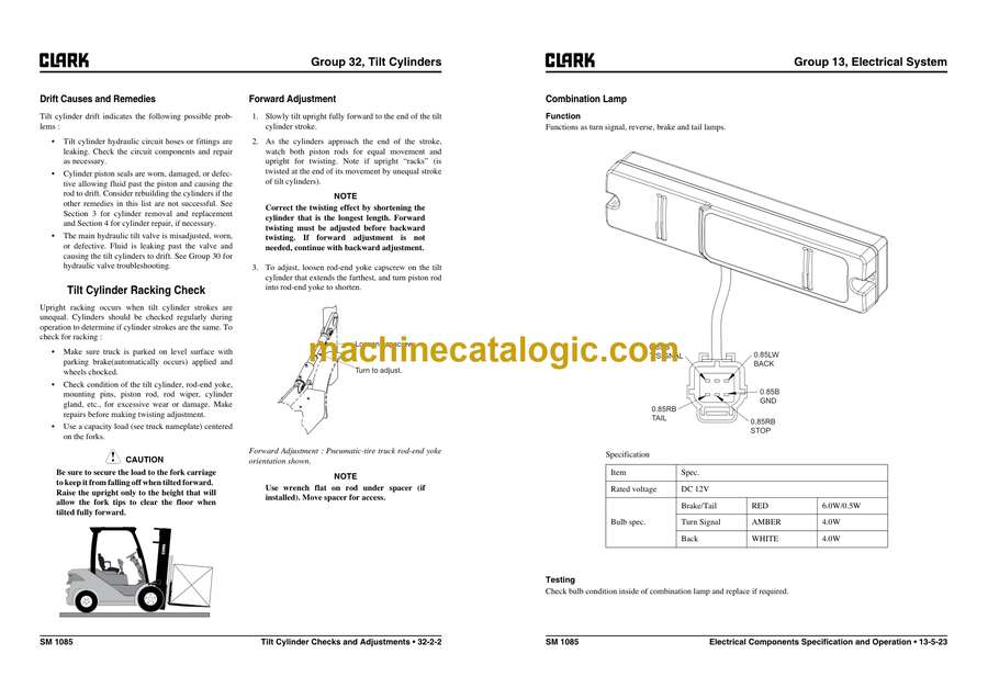
Section 1 Tilt Cylinder Specifications and Description
Section 2 Tilt Cylinder Checks and Adjustments
Section 3 Tilt Cylinder Removal and Replacement
Section 4 Tilt Cylinder Overhaul
GROUP 34 UPRIGHTS
Section 1 Upright Specifications and Description
Section 2 Troubleshooting
Section 3 Upright Inspection
Section 4 Carriage and Upright Roller Clearance Checks and Shim Adjustments
Section 5 Cylinder Removal, Shimming, Overhaul, and Replacement
Section 6 Upright Chain Inspection, Adjustment, and Replacement
Section 7 Fork and Carriage Removal and Replacement
Section 8 Upright Removal and Replacement
GROUP 38 COUNTERWEIGHT AND CHASSIS
Section 1 Counterweight Specifications and Description
Section 2 Counterweight Removal and Replacement
Section 3 Overhead Guard/Operator’s Cell Removal and Replacement
Section 4 Floorboard, Cowls, and Seat Deck Removal and Replacement
Section 5 Operator’s Seat Removal and Replacement
GROUP 40 SPECIFICATIONS
Section 1 Nameplates and Decals
Section 2 General Specifications
Section 3 Hydraulic Fitting Tightening Procedure


