Format: PDF (Printable Document)
File Language: English
File Pages: 290
File Size: 40.66 MB (Speed Download Link)
Brand: CNH
Model: 5500 Flex Hoe 700 P2060 Air Hoe Drill
Part No: 92318852
Date: September 2024
Type of Document: Assembly Instructions
$ 45
1 SAFETY INFORMATION
Safety rules . . . . . . . . . . . . . . . . . . . . . . . . . . . . . . . . . . . . . . . . . . . . . . . . . . . . . . . . . . . . . . . . . . . . . . . . . . . . . . . . . 1-1
2 GENERAL INFORMATION
Seeding – Basic instructions . . . . . . . . . . . . . . . . . . . . . . . . . . . . . . . . . . . . . . . . . . . . . . . . . . . . . . . . . . . . . . . . 2-1
Torque . . . . . . . . . . . . . . . . . . . . . . . . . . . . . . . . . . . . . . . . . . . . . . . . . . . . . . . . . . . . . . . . . . . . . . . . . . . . . . . . . . . . . . 2-2
Torque – Standard torque data for hydraulic connections . . . . . . . . . . . . . . . . . . . . . . . . . . . . . . . . . . 2-7
Seeding – Basic instructions – Required building and equipment . . . . . . . . . . . . . . . . . . . . . . . . . 2-14
3 ASSEMBLY
AIR HOE DRILL ASSEMBLY
Preparing for assembly . . . . . . . . . . . . . . . . . . . . . . . . . . . . . . . . . . . . . . . . . . . . . . . . . . . . . . . . . . . . . . . 3-1
Frame – Prepare Air hoe drill for assembly . . . . . . . . . . . . . . . . . . . . . . . . . . . . . . . . . . . . . . . . 3-1
Center section wheel hubs . . . . . . . . . . . . . . . . . . . . . . . . . . . . . . . . . . . . . . . . . . . . . . . . . . . . . . . . . . . 3-2
Caster wheels – Install The center section wheel hubs . . . . . . . . . . . . . . . . . . . . . . . . . . . . 3-2
Front hitch . . . . . . . . . . . . . . . . . . . . . . . . . . . . . . . . . . . . . . . . . . . . . . . . . . . . . . . . . . . . . . . . . . . . . . . . . . . . 3-4
Tongue or hitch Front hitch – Install The hitch assembly . . . . . . . . . . . . . . . . . . . . . . . . . . . 3-4
Tongue or hitch Front hitch – Install The hitch latch and hose holder . . . . . . . . . . . . . . 3-7
Tongue or hitch Front hitch – Install The hitch support braces . . . . . . . . . . . . . . . . . . . . . 3-9
Tongue or hitch Front hitch – Install The left and right fold arms . . . . . . . . . . . . . . . . . . 3-10
Center section wheels . . . . . . . . . . . . . . . . . . . . . . . . . . . . . . . . . . . . . . . . . . . . . . . . . . . . . . . . . . . . . . . 3-11
Caster wheels – Install The center section wheels . . . . . . . . . . . . . . . . . . . . . . . . . . . . . . . . 3-11
Inner and outer wing assembly . . . . . . . . . . . . . . . . . . . . . . . . . . . . . . . . . . . . . . . . . . . . . . . . . . . . . . 3-12
Frame – Install The universal joint . . . . . . . . . . . . . . . . . . . . . . . . . . . . . . . . . . . . . . . . . . . . . . . . 3-12
Frame – Install The universal joint . . . . . . . . . . . . . . . . . . . . . . . . . . . . . . . . . . . . . . . . . . . . . . . . 3-13
Frame – Install The inner wing (PIN YJS078001 and after) . . . . . . . . . . . . . . . . . . . . . . . 3-14
Caster wheels – Install The inner wheel casters and tires . . . . . . . . . . . . . . . . . . . . . . . . 3-15
Frame – Install The outer wing . . . . . . . . . . . . . . . . . . . . . . . . . . . . . . . . . . . . . . . . . . . . . . . . . . . . 3-17
Frame – Paint The universal joint and wing hinge pins . . . . . . . . . . . . . . . . . . . . . . . . . . . 3-18
Caster wheels – Install The outer wing casters and tires (up to PIN YNS104000) 3-19
Caster wheels – Install The outer wing casters and tires (from PIN YNS104001 and
AFTER) . . . . . . . . . . . . . . . . . . . . . . . . . . . . . . . . . . . . . . . . . . . . . . . . . . . . . . . . . . . . . . . . . . . . . . . . . . . 3-21
Lockshaft assembly . . . . . . . . . . . . . . . . . . . . . . . . . . . . . . . . . . . . . . . . . . . . . . . . . . . . . . . . . . . . . . . . . 3-23
Frame – Install The center section lockshaft tube . . . . . . . . . . . . . . . . . . . . . . . . . . . . . . . . . 3-23
Frame – Install The inner section lockshaft tube . . . . . . . . . . . . . . . . . . . . . . . . . . . . . . . . . . 3-24
Frame – Install The outer section lockshaft tube . . . . . . . . . . . . . . . . . . . . . . . . . . . . . . . . . . 3-25
Depth gauge assembly . . . . . . . . . . . . . . . . . . . . . . . . . . . . . . . . . . . . . . . . . . . . . . . . . . . . . . . . . . . . . . 3-27
Depth control – Install The depth gauge . . . . . . . . . . . . . . . . . . . . . . . . . . . . . . . . . . . . . . . . . . 3-27
Locking caster assembly . . . . . . . . . . . . . . . . . . . . . . . . . . . . . . . . . . . . . . . . . . . . . . . . . . . . . . . . . . . . 3-28
Caster wheels – Install The locking caster latch . . . . . . . . . . . . . . . . . . . . . . . . . . . . . . . . . . 3-28
Actuator latch assembly . . . . . . . . . . . . . . . . . . . . . . . . . . . . . . . . . . . . . . . . . . . . . . . . . . . . . . . . . . . . . 3-34
Transport locking assembly Swinging mechanical latch – Install The actuator latch arm
. . . . . . . . . . . . . . . . . . . . . . . . . . . . . . . . . . . . . . . . . . . . . . . . . . . . . . . . . . . . . . . . . . . . . . . . . . . . . . . . . . . . 3-34
Rockshaft assembly . . . . . . . . . . . . . . . . . . . . . . . . . . . . . . . . . . . . . . . . . . . . . . . . . . . . . . . . . . . . . . . . . 3-36
Frame – Install The center to inner rockshaft link (PIN YJS078001 and after) . . . . 3-36
Frame – Install The intermediate rockshaft (PIN YJS078001 and after) . . . . . . . . . . 3-37
Frame – Install The intermediate rockshaft (PIN YJS078001 and after) . . . . . . . . . . 3-38
Frame – Install The intermediate rockshaft link pieces . . . . . . . . . . . . . . . . . . . . . . . . . . . . 3-39
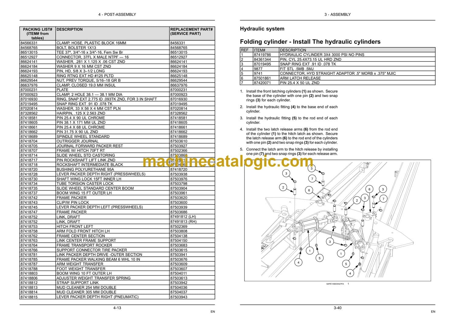
Hydraulic system . . . . . . . . . . . . . . . . . . . . . . . . . . . . . . . . . . . . . . . . . . . . . . . . . . . . . . . . . . . . . . . . . . . . 3-40
Folding cylinder – Install The hydraulic cylinders . . . . . . . . . . . . . . . . . . . . . . . . . . . . . . . . . 3-40
Depth control – Install The depth gauge fittings . . . . . . . . . . . . . . . . . . . . . . . . . . . . . . . . . . . 3-43
Folding control valve – Install The valve plate . . . . . . . . . . . . . . . . . . . . . . . . . . . . . . . . . . . . 3-44
Folding control valve – Install The left and right tension links . . . . . . . . . . . . . . . . . . . . . 3-45
Folding control valve – Install The lockshaft valve assembly link . . . . . . . . . . . . . . . . . 3-46
Folding control valve – Install The inner wing control valve . . . . . . . . . . . . . . . . . . . . . . . 3-47
Hydraulic systems – Install The hydraulic system . . . . . . . . . . . . . . . . . . . . . . . . . . . . . . . . . 3-49
Hydraulic systems – Hydraulic schema Hydraulic schematic layout . . . . . . . . . . . . . . 3-54
Hydraulic systems – Install Hydraulic hoses – routing . . . . . . . . . . . . . . . . . . . . . . . . . . . . . 3-63
Lockshaft lock assembly . . . . . . . . . . . . . . . . . . . . . . . . . . . . . . . . . . . . . . . . . . . . . . . . . . . . . . . . . . . . 3-68
Product handling and delivery drive system – Install The lockshaft lock assembly 3-68
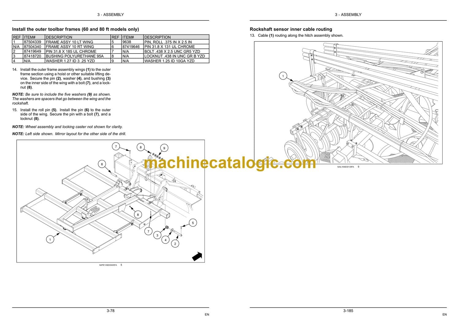
Toolbar frame assembly . . . . . . . . . . . . . . . . . . . . . . . . . . . . . . . . . . . . . . . . . . . . . . . . . . . . . . . . . . . . . 3-74
Frame – Install The toolbar assembly . . . . . . . . . . . . . . . . . . . . . . . . . . . . . . . . . . . . . . . . . . . . . 3-74
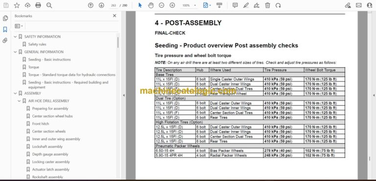
Frame – Install The outer and intermediate toolbar frame spring kit . . . . . . . . . . . . . . 3-79
Frame – Install The boom latch chain bracket . . . . . . . . . . . . . . . . . . . . . . . . . . . . . . . . . . . . 3-87
Folding control valve – Install The valve control arm . . . . . . . . . . . . . . . . . . . . . . . . . . . . . . 3-88
Cylinder – Install The cylinders on the toolbars . . . . . . . . . . . . . . . . . . . . . . . . . . . . . . . . . . . 3-89
Hydraulic systems – Install The hydraulic hoses to the toolbar cylinders . . . . . . . . . 3-90
Trips and openers . . . . . . . . . . . . . . . . . . . . . . . . . . . . . . . . . . . . . . . . . . . . . . . . . . . . . . . . . . . . . . . . . . . 3-93
Tillage tripping system – Install The trips and openers . . . . . . . . . . . . . . . . . . . . . . . . . . . . 3-93
Rear hitch assembly. . . . . . . . . . . . . . . . . . . . . . . . . . . . . . . . . . . . . . . . . . . . . . . . . . . . . . . . . . . . . . . . . 3-94
Tongue or hitch Rear hitch – Install The rear hitch hookup . . . . . . . . . . . . . . . . . . . . . . . 3-94
Weight transfer assembly . . . . . . . . . . . . . . . . . . . . . . . . . . . . . . . . . . . . . . . . . . . . . . . . . . . . . . . . . . . 3-96
Frame – Install The center section weight transfer arm . . . . . . . . . . . . . . . . . . . . . . . . . . . 3-96
Frame – Install the inner, intermediate, and outer section weight transfer arms . . 3-98
Packer and rocker frame assembly . . . . . . . . . . . . . . . . . . . . . . . . . . . . . . . . . . . . . . . . . . . . . . . . 3-100
Frame – Install The packer frame . . . . . . . . . . . . . . . . . . . . . . . . . . . . . . . . . . . . . . . . . . . . . . . . 3-100
Frame – Install The transport rocker frame . . . . . . . . . . . . . . . . . . . . . . . . . . . . . . . . . . . . . . 3-101
Rear wheel – Install The rear wheel assembly . . . . . . . . . . . . . . . . . . . . . . . . . . . . . . . . . . . 3-103
Frame – Install The center section packer link . . . . . . . . . . . . . . . . . . . . . . . . . . . . . . . . . . . 3-104
Frame – Install The center section packer frame . . . . . . . . . . . . . . . . . . . . . . . . . . . . . . . . 3-107
Frame – Install The inner, intermediate, and outer wing packer t-bar frames . . . . 3-109
Frame – Install The inner, intermediate, and outer section drive links, and support strap
. . . . . . . . . . . . . . . . . . . . . . . . . . . . . . . . . . . . . . . . . . . . . . . . . . . . . . . . . . . . . . . . . . . . . . . . . . . . . . . . . . . 3-111
Depth control assembly . . . . . . . . . . . . . . . . . . . . . . . . . . . . . . . . . . . . . . . . . . . . . . . . . . . . . . . . . . . . 3-112
Depth control – Install The depth control link assembly . . . . . . . . . . . . . . . . . . . . . . . . . . 3-112
Depth control – Install The cable from the center toolbar to the depth control . . . 3-114
Outrigger frame assembly . . . . . . . . . . . . . . . . . . . . . . . . . . . . . . . . . . . . . . . . . . . . . . . . . . . . . . . . . . 3-116
Frame – Install The outrigger frame . . . . . . . . . . . . . . . . . . . . . . . . . . . . . . . . . . . . . . . . . . . . . . 3-116
Frame – Detailed view The outrigger for the press wheels (layout) . . . . . . . . . . . . . . 3-118
Frame – Install rear wing braces . . . . . . . . . . . . . . . . . . . . . . . . . . . . . . . . . . . . . . . . . . . . . . . . . 3-129
Packer press wheel assembly. . . . . . . . . . . . . . . . . . . . . . . . . . . . . . . . . . . . . . . . . . . . . . . . . . . . . . 3-131
Press wheel – Install The packers (machines with rubber and steel press wheels only)
. . . . . . . . . . . . . . . . . . . . . . . . . . . . . . . . . . . . . . . . . . . . . . . . . . . . . . . . . . . . . . . . . . . . . . . . . . . . . . . . . . . 3-131
Press wheel – Install the packers (pneumatic press wheels) . . . . . . . . . . . . . . . . . . . . 3-136
Press wheel – Detailed view Packer layouts – 80 ft . . . . . . . . . . . . . . . . . . . . . . . . . . . . . . 3-141
Press wheel – Detailed view Packer layouts – 70 ft . . . . . . . . . . . . . . . . . . . . . . . . . . . . . . 3-147
Press wheel – Detailed view Packer layouts – 60 ft . . . . . . . . . . . . . . . . . . . . . . . . . . . . . . 3-153
Press wheel – Install The packer interference spring assembly (optional) . . . . . . . 3-161
Rear hitch assembly. . . . . . . . . . . . . . . . . . . . . . . . . . . . . . . . . . . . . . . . . . . . . . . . . . . . . . . . . . . . . . . . 3-162
Hitches, drawbars, and implement couplings – Install The tow behind (TBH) rear drill
hitch . . . . . . . . . . . . . . . . . . . . . . . . . . . . . . . . . . . . . . . . . . . . . . . . . . . . . . . . . . . . . . . . . . . . . . . . . . . . . . 3-162
Wing draft link assembly . . . . . . . . . . . . . . . . . . . . . . . . . . . . . . . . . . . . . . . . . . . . . . . . . . . . . . . . . . . 3-164
Frame – Install The wing draft link tubes . . . . . . . . . . . . . . . . . . . . . . . . . . . . . . . . . . . . . . . . . 3-164
Packer kickout assembly . . . . . . . . . . . . . . . . . . . . . . . . . . . . . . . . . . . . . . . . . . . . . . . . . . . . . . . . . . . 3-168
Frame – Install The packer kickout cable . . . . . . . . . . . . . . . . . . . . . . . . . . . . . . . . . . . . . . . . 3-168
Toolbar chain connection . . . . . . . . . . . . . . . . . . . . . . . . . . . . . . . . . . . . . . . . . . . . . . . . . . . . . . . . . . . 3-170
Frame – Install The chain connections between toolbars (80 ft) . . . . . . . . . . . . . . . . . 3-170
Frame – Install The chain connection between toolbars (70 ft) . . . . . . . . . . . . . . . . . . 3-171
Frame – Install The chain connection between toolbars (60 ft) . . . . . . . . . . . . . . . . . . 3-172
Reflectors, safety lighting & slow moving (SMV) emblem . . . . . . . . . . . . . . . . . . . . . . . . . . 3-173
External lighting – Install The transport lighting assembly . . . . . . . . . . . . . . . . . . . . . . . 3-173
Wing/Boom traveling sensors – Install The slow moving vehicle (SMV) sign (up to PIN
YNS104000) . . . . . . . . . . . . . . . . . . . . . . . . . . . . . . . . . . . . . . . . . . . . . . . . . . . . . . . . . . . . . . . . . . . . . 3-175
Wing/Boom traveling sensors – Install The slow moving vehicle (SMV) sign ( PIN
YNS104001 and AFTER) . . . . . . . . . . . . . . . . . . . . . . . . . . . . . . . . . . . . . . . . . . . . . . . . . . . . . . . . 3-176
Sensor and harness installation . . . . . . . . . . . . . . . . . . . . . . . . . . . . . . . . . . . . . . . . . . . . . . . . . . . . 3-177
Cab seeding controls – Install The electronic harness and sensors . . . . . . . . . . . . . 3-177
Cab seeding controls – Install The hose support strap . . . . . . . . . . . . . . . . . . . . . . . . . . . 3-187
Jack storage location . . . . . . . . . . . . . . . . . . . . . . . . . . . . . . . . . . . . . . . . . . . . . . . . . . . . . . . . . . . . . . . 3-188
Frame – Install The front hitch jack onto the storage location . . . . . . . . . . . . . . . . . . . . 3-188
Grease pivot points . . . . . . . . . . . . . . . . . . . . . . . . . . . . . . . . . . . . . . . . . . . . . . . . . . . . . . . . . . . . . . . . . 3-189
Frame pivot – Grease All pivot locations . . . . . . . . . . . . . . . . . . . . . . . . . . . . . . . . . . . . . . . . . 3-189
Hydraulic run-in sequence. . . . . . . . . . . . . . . . . . . . . . . . . . . . . . . . . . . . . . . . . . . . . . . . . . . . . . . . . . 3-196
Hydraulic systems – Pressure test – Hydraulic circuit run-in sequence . . . . . . . . . . 3-196
Hydraulic systems – Pressure test – Valve position reference . . . . . . . . . . . . . . . . . . . 3-208
Hydraulic systems – Check List . . . . . . . . . . . . . . . . . . . . . . . . . . . . . . . . . . . . . . . . . . . . . . . . . . 3-209
ADJUSTMENTS
Initial machine leveling . . . . . . . . . . . . . . . . . . . . . . . . . . . . . . . . . . . . . . . . . . . . . . . . . . . . . . . . . . . . . 3-210
Frame – Adjust The air hoe drill levelling . . . . . . . . . . . . . . . . . . . . . . . . . . . . . . . . . . . . . . . . . 3-210
Adjustments . . . . . . . . . . . . . . . . . . . . . . . . . . . . . . . . . . . . . . . . . . . . . . . . . . . . . . . . . . . . . . . . . . . . . . . . 3-223
Depth control – Adjust The headland valve spring bolt . . . . . . . . . . . . . . . . . . . . . . . . . . 3-223
Caster wheels – Adjust The locking caster alignment . . . . . . . . . . . . . . . . . . . . . . . . . . . . 3-224
Transport locking assembly Extending mechanical latch – Adjust The lockshaft engagement
bolt . . . . . . . . . . . . . . . . . . . . . . . . . . . . . . . . . . . . . . . . . . . . . . . . . . . . . . . . . . . . . . . . . . . . . . . . . 3-225
Press wheel – Adjust The packer kickout cable . . . . . . . . . . . . . . . . . . . . . . . . . . . . . . . . . . 3-226
Tillage – Adjust The sweep pitch . . . . . . . . . . . . . . . . . . . . . . . . . . . . . . . . . . . . . . . . . . . . . . . . . 3-227
Pressure system – Adjust The packing pressure . . . . . . . . . . . . . . . . . . . . . . . . . . . . . . . . 3-229
Tool – Adjust The heavy harrow closer (option) . . . . . . . . . . . . . . . . . . . . . . . . . . . . . . . . . . 3-230
Tool – Adjust The wing section harrow tines . . . . . . . . . . . . . . . . . . . . . . . . . . . . . . . . . . . . . 3-231
Tool – Adjust (option) . . . . . . . . . . . . . . . . . . . . . . . . . . . . . . . . . . . . . . . . . . . . . . . . . . . . . . . . . . . . . 3-232
Seeding control system – Adjust The system sensors . . . . . . . . . . . . . . . . . . . . . . . . . . . 3-234
Hydraulic systems – Assemble Cross tillage hydraulic hoses on a large hoe drill – for
tow behind (TBH) air carts . . . . . . . . . . . . . . . . . . . . . . . . . . . . . . . . . . . . . . . . . . . . . . . . . . . . . . . 3-236
4 POST-ASSEMBLY
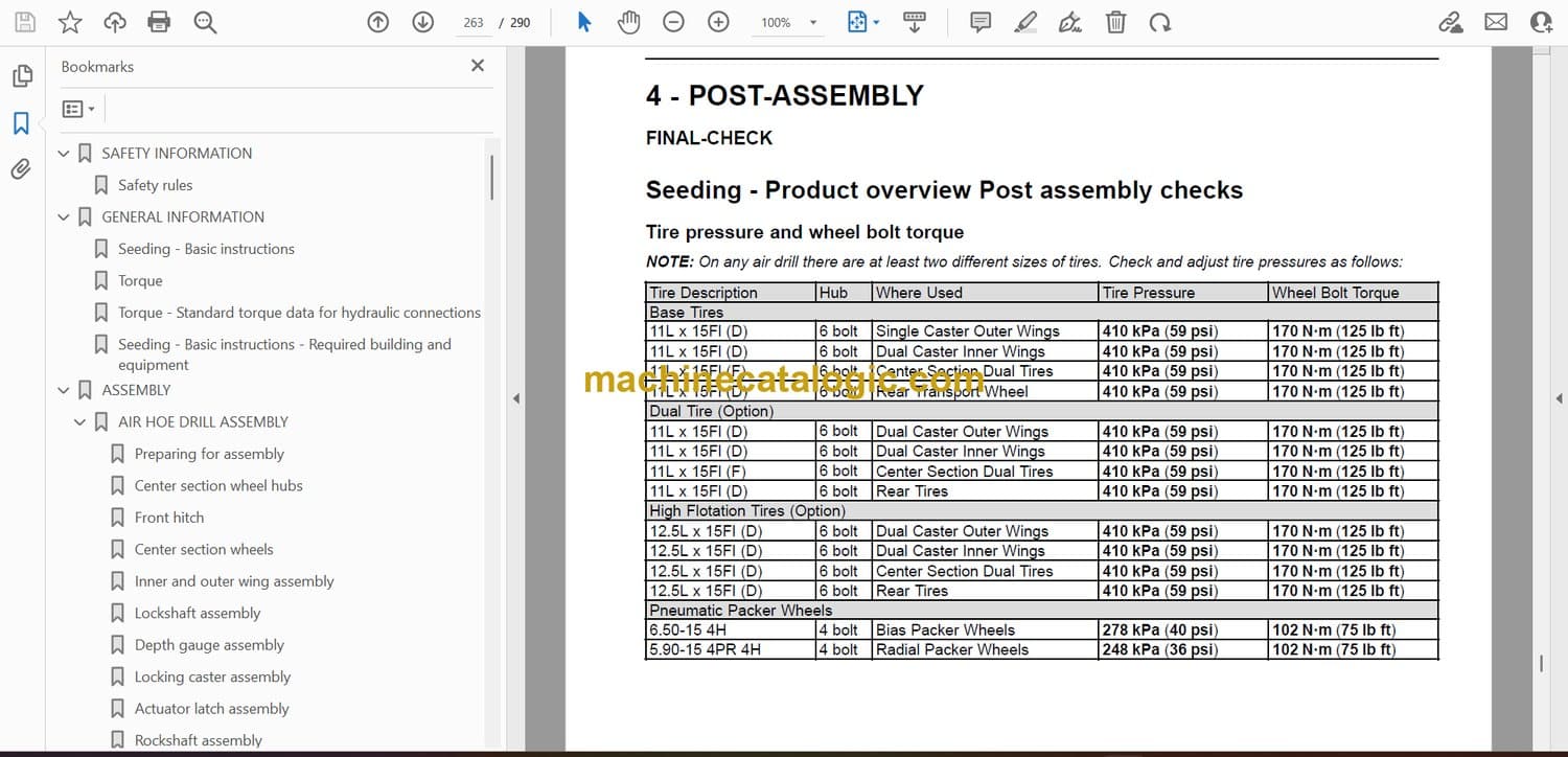
FINAL-CHECK
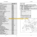
Seeding – Product overview Post assembly checks . . . . . . . . . . . . . . . . . . . . . . . . . . . . . . . . . . . 4-1
Seeding – Product overview Post assembly check list . . . . . . . . . . . . . . . . . . . . . . . . . . . . . . . . . 4-2
Seeding – Product overview – Service parts cross reference list (FC) . . . . . . . . . . . . . . . . . 4-3
Seeding – Product overview – Service parts cross reference list (CIH) . . . . . . . . . . . . . . . 4-11
Seeding – Product overview – Service parts cross reference list (NH) . . . . . . . . . . . . . . . . 4-19


