A Demag AC 120 is a multi-axle all terrain crane. It drives on public roads, then sets up on outriggers and works on site with a telescopic boom. A rental or fleet company reaches for this set when it wants every document for one model in one place, so operators, mechanics and the parts desk are all working from the same files.
What this manual set helps you do
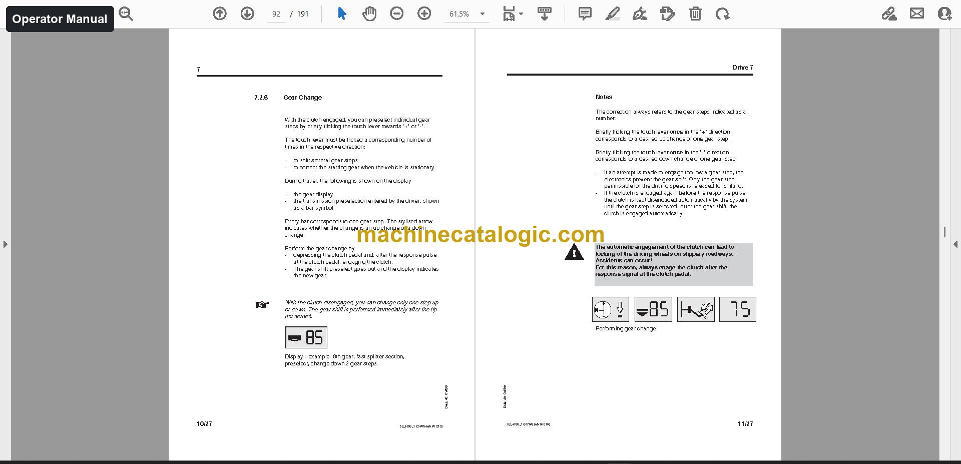
- Operate the crane by following the operator manual: safety instructions, engine, outrigger support, superstructure cab and counterweight setup.
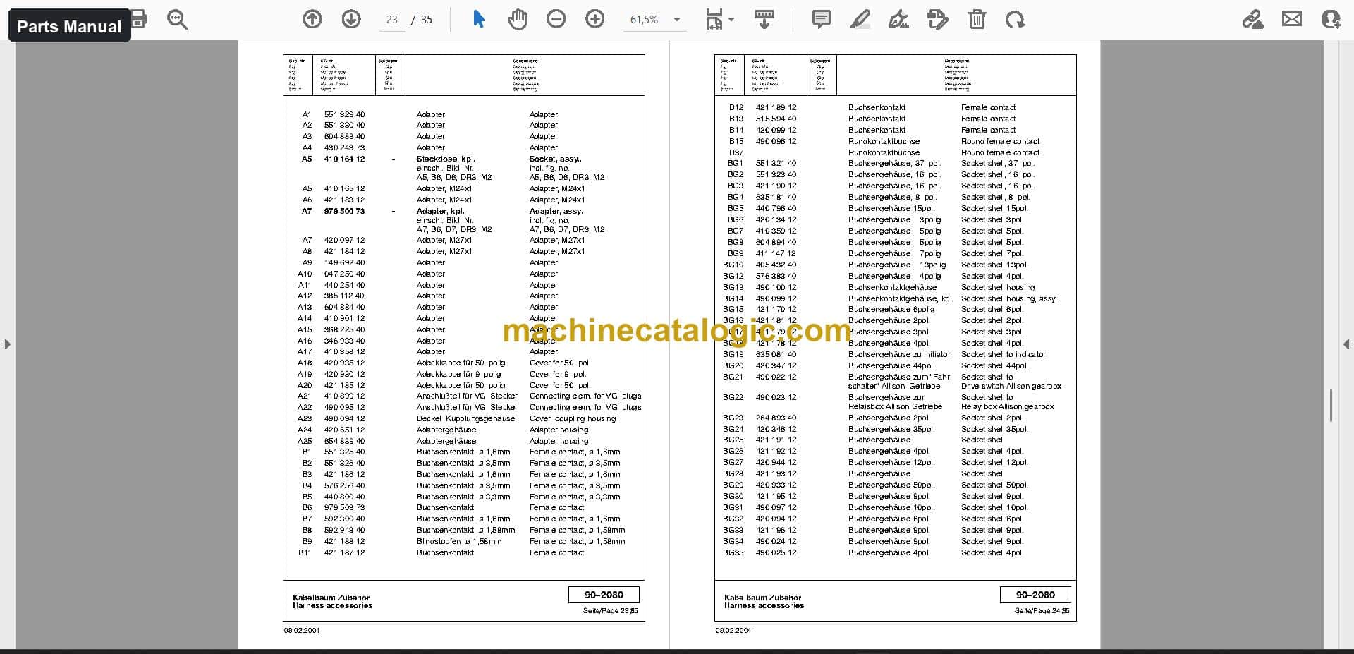
- Order parts with the parts manual, which has exploded views for assemblies such as the fuel system, hoist limit switch and top outrigger controls.
- Trace hydraulic and electrical circuits in the schematics, 36 files and 413 pages.
- Plan lifts with the load charts, and check the technical data before a job.
- Verify load moment indicator details in the component manuals, which cover the PAT A 713 to A 716 and DS 150 units.
Who this is for
A rental fleet manager gets one set that serves the yard, the cab and the parts desk for the same machine. A workshop taking on a used AC 120 gets the working documents without hunting through separate sources.
FAQ
Q: What do I receive and how is it organised?
A: One download with 533 files (324 PDF) and 3,238 PDF pages. The operator manual is 436 pages in English, and the parts manual is 728 pages in German across 242 files. The rest is grouped as schematics, load charts, technical data, assembly and installation, training documents, component manuals and other documents.
Q: Which machine does it fit?
A: The Demag AC 120 all terrain crane. The component manuals include the PAT A 713, A 714, A 715, A 716 and DS 150 load moment indicators.
Q: How does it fit my job?
A: Operators use the operator manual for setup and daily work. Mechanics use the schematics and component manuals, and the parts desk uses the exploded views to order. Training documents are there for bringing new crew up to speed.
Download it, hand each team its section, and every person working on the AC 120 has the documents for their part of the job.
📘 Show Index
Table of Contents:
Operator Manual Table of Contents
436 pages, 2 files
- Publication e395_1-1000 (245 pages)
- Safety Instructions
- Structure of the Mobile Crane
- Serial Plate
- Safety Signs
- Overview
- Crane Operator's Cab
- Control Elements in the Crane Operator's Cab
- Indicator Lights in the Crane Operator's Cab
- Engine
- Before Starting
- Starting Procedure
- After Starting the Engine
- Supporting the Crane on Outriggers from the
- Superstructure Cab (optional)
- Slewing
- Preparations for Slewing
- Slewing the Superstructure
- Slew Speeds
- Support Area (optional)
- Counterweight
- Procedure for Fitting the Counterweigt
- Allocation of Counterweights for the Various Configurations
- t Counterweight Combination
- proceed as follows
- Safety Equipment
- General Information
- Selection Reeving Number, Extension Sequence
- Counterweight Configuration and Outrigger Support Area
- (Telecode)
- in transport position
- LIMIT Setting (optional)
- Operating the Load Limit Device
- Hoist Limit Switch
- "Lift" Hoist Limit Switch
- "Lower hoist end limit switch"
- Bridging the Load Limit Device
- Notes on Operation
- General Notes on Operation
- Raising a Load Using Several Cranes
- Checking the Safety Measures
- Telescoping
- Telescoping the Main Boom
- Telescoping Procedure
- Luffing
- Raising and Lowering the Main Boom
- Raising and Lowering the Main Boom in High Range
- Luffing Speeds
- Hoist 2
- Auxiliary Head Sheave for Hoist 2
- Positioning of the Ropes
- Raising and Lowering a Load with Hoist 2 (optional)
- Hoist Speeds
- Main Boom Extension
- General
- Fitting the Main Boom Extension
- Folding the Main Boom Extension
- Operating Position
- into the Operating Position
- Folding the Main Boom Extension
- Operating Position 20o or 40o
- Fitting Procedure
- Securing the Box Top Piece to the Main Boom
- Special Extension Sequence
- Heating and Ventilation
- Operating the Heating and Ventilation
- Reeving
- Rope Equipment and Reeving
- Publication e395_1-2000 (191 pages)
- Safety Instructions
- Crane Chassis
- Driver's Cab
- Driver's Cab
- Dashboard Installation
- Engine
- Checks before Starting
- Starting
- Stopping the Engine
- Driving
- Checks before Driving
- General
- Road Traffic Licensing Regulations)
- Driving on the Construction Site
- Driving in Erect Mode
- Transmission
- Construction
- Operation
- Displays
- Brakes
- Braking System
- Service Brake
- Parking Brake
- Exhaust Brake (Sustained-Action Brake)
- Steering
- Steering during Road Travel
- Independent Rear Axle Steering
- Differential Locks
- Hydraulic Suspension
- Suspension Circuits
- Overall Level Adjustment
- Monitoring the Hydraulic Suspension System while Driving
- Outriggers
- Instructions for Supporting the Crane on the Outriggers
- Arrangement of the Control Elements for the Outriggers
- Before Extending the Outriggers
- Transport Condition)
- Configured Condition)
- Permissible Ground Pressures
- Supporting the Crane with Monitoring of
- the Outrigger Support Area (Optional)
- Parking
- Leaving the Vehicle in Transport Condition
- Leaving the Crane in Configured Condition and
- with Outriggers Extended
- Towing the Crane and Towing the Crane to Start
- Towing the Crane to Start
- General Towing Regulations
- Towing the Crane Free on Soft Ground
- Heating and Ventilation
- Operation of the Heating and Ventilation System
- Instructions for Winter Operation
Parts Manual Table of Contents
728 pages, 242 files
- Serial No. 76287 (714 pages)
- Control Lever Decal Allocation
- Flow Indicator Assembly Parts
- Suspension Cylinder Parts
- Slave Cylinder Parts
- Resilient Cylinder Parts
- Hydraulic Circuit Schematics
- Semi-Integral Power Steering Parts
- Planetary Gear Parts
- 32-Ton Single Hook Block Parts
- 80-Ton Twin Hook Block Parts
- Water Cooler Parts
- Valve Block Parts List
- Flow Control Valve Parts List
- Expander Unit Parts List
- Hydraulic Motor Parts List
- Slew Gear Parts List
- Winch Gear Parts List
- Clutch Pedal Parts List
- Hoist Limit Switch Parts List
- Distribution Box Inner Case Parts List
- Spotlight Parts List
- Painting, Decals and Stop Pads Parts List
- Crane Component Identification Diagram
- Superstructure Maintenance Parts List
- Travel Lock Parts
- Superstructure Mounting Parts
- Luffing Cylinder Mounting Parts
- Assembly Parts Drawings
- Counterweight Locking Parts
- Drive Covering Parts
- Control Unit Covering Parts
- Slew Ring Parts
- Drive Parts
- Speed Control and Engine Shutdown Parts
- Hydraulic Engine Parts
- Cooling System Parts
- Air Filter Parts
- Fuel System Parts
- Exhaust System with Spark Arrestor
- AC 120 Refrigerant Compressor Parts List
- Hoist Gear I and II Parts
- Slew Gear Parts
- Hydraulic Oil Tank Parts
- Hydraulic Control Schematic
- Hoist Control Block Parts
- Hydraulic System Schematic
- Additional Hoist Gear Hydraulic Parts
- Dolly Hydraulic Parts
- Cabin Assembly Parts
- Coolant Heater Parts
- Air Conditioning Assembly Parts
- Superstructure Electrical Parts
- Electric Cabin Parts
- Dashboard Parts
- Central Electrical Parts
- Top Outrigger Controls Parts
- Superstructure Harness Wiring Diagram
- Pilot Control Harness Wiring Diagram
- Engine Harness Wiring Diagram
- Air Conditioning Harness Wiring Diagram
- Aerodynamic Safety Light Harness Diagram
- Rope Equipment Parts List
- Telescopic Boom Parts Drawings
- Basic Case Parts List
- Inner Case Parts List
- Optional Sheaves and Head Sheave
- Foldable Head Sheave Parts
- Energy Chain Parts
- Additional Top Roller Parts
- Basic Boom Parts
- Top Section Case Parts
- Runner Assembly Parts
- Travel Lock MBE Parts
- Electric Main Boom Parts
- Cable Drum Mounting Parts
- Distribution Box Main Boom Head
- Aerodynamic Safety Light
- Anemometer Assembly
- Basic Boom Section Harness
- Top Section Case Harness
- Distributor Box Main Boom Extension
- Reverse Motion Warning Buzzer
- Tools and Accessories Spare Parts List
- AC 395 Crane Assembly Illustration
- Machine Maintenance Parts List
- Front Frame Covering and Mounting Parts
- Rear Frame Covering and Mounting Parts
- Left-Hand Covering Parts
- AC 120 Parts Catalog Section
- Engine Covering Parts
- Spare Wheel Suspension Parts
- Hook Block Support Parts
- Support Assembly Parts
- Front Outrigger Assembly
- Rear Outrigger Assembly
- Mounting Slip Ring
- Ladder Assembly
- Engine and Gearbox Mounting
- Engine Control Parts
- Radiator System Parts
- Auxiliary Radiator Parts
- Exhaust System with Spark Arrester
- Refrigerator Compressor Mounting
- Speed Control Assembly
- Component Assembly Drawings
- Pneumatic System, Left
- Right Pneumatic System Parts
- Hydraulic and Axle Parts
- Axle Assembly Parts
- Dolly Hydraulics Parts
- Gearbox and Driver’s Cab Parts
- Steering Assembly Parts
- Auxiliary Heating Parts
- Electric Chassis Parts
- Right-Hand Traffic Lighting Equipment
- Central Electrical Assembly
- PLC Components
- Mounting Outrigger Pressure Detection
- Front Left Harness
- Front Right Harness
- Rear Left Harness
- Rear Right Harness
- Underride Guard Harness Assembly
- Engine Wiring Harness Assembly
- Axle Mounting 10x6x8
- First Axle Assembly
- Second Axle Assembly
- Third Axle Mounting Parts
- Fourth Axle Mounting Parts
- Fifth Axle Mounting Parts
- Distributor Gear Mounting Parts
- Joint Shaft Mounting Parts
- 20.50-Inch Wheels and Tires
- Hook Suspension Parts
- Control Valve Parts
- Gear Pump Parts
- Heat Exchanger Parts
- Directional Spool Valve Assembly Parts
- Gearbox and Periphery Parts
- Converter Housing Parts
- Turbine Shaft Parts
- Pump Parts
- Transmission Housing Parts
- Separation Clutch Parts
- Control Unit Parts
- Control Unit Wiring Parts
- Torque Converter Parts List
- Transmission Parts List
- Layshaft Parts List
- Main Shaft Parts List
- Gearshift System Parts List
- Gearshift Housing Parts List
- Pneumatic Components Parts List
- Cylinder Parts List
- Slip Ring Set Parts List
- Component Assembly Parts Drawings
- GV Shift System Parts
- Gear Shift Cover Parts
- Planetary Drive Parts
- Synchronizer Parts
- GP Shift System Parts
- Seal Kits Parts List
- Steering Column Parts List
- Luffing Cylinder Parts List
- Control Block Parts List
- Operator Seat Parts List
- Oil Cooler Parts List
- Operation Box Parts List
- Hydraulic Steering Rod Parts List
- High Pressure Filter Parts List
- Telescopic Cylinder Parts List
- Crane Component Parts List
- Anemometer Parts List
- Directional Spool Valve Parts List
- Accelerator Pedal Parts
- Return Filter Parts
- Control Block Parts
- Heat Exchanger Assembly Parts
- Component Parts Catalog
- Heater Assembly Parts
- Distributor Gear Parts
- Main Calculator Parts
- Support Cylinder Parts
- Outrigger Pressure Detection Parts
- Horizontal Cylinder Parts
- Operator Seat Parts
- Support Pressure Indicator Parts
- Fire Extinguisher Mounting Parts
- Brake Parts List
- Brake Assembly Parts List
- Planetary Gear Parts List
- Condenser Parts List
- Brake Valve Assembly Parts
- High Pressure Filter Parts
- Steering Axle Parts
- Steering Drive Axle Parts
- Rigid Axle 3 Parts
- Axle 5 Parts
- Axle Drive Parts
- Differential Housing Parts
- Diesel Engine Oil Filter Parts
- Luffing Cylinder Parts
- Cabin Parts List
- Diesel Engine Parts
- Cab Assembly Parts
- Brake Assembly Parts
- Absorber Assembly Parts
- 63-Ton Twin Hook Block Parts
- Control Transmitter Parts Drawing
- Mirror Support Assembly AC395
- Heater Assembly
- Publication AC00120-76287_de / Serial No. 76287 (14 pages)
Also in this set
- Schematics (36 files, 413 pages)
- Load charts (23 files, 125 pages)
- Technical data (1 file, 22 pages)
- Assembly and installation (17 files, 14 pages)
- Training documents (7 files, 1,202 pages)
- Component manuals (92 files, 298 pages)
- PAT A 713 Load Moment Indicator
- PAT A 714 Load Moment Indicator
- PAT A 715 Load Moment Indicator
- PAT A 716 Load Moment Indicator
- PAT DS 150 Load Moment Indicator
- PAT General Documents
- PAT KEDV V2.02 Load Moment Indicator
- PAT modular PDC Load Moment Indicator
- PAT PDC A 700 Load Moment Indicator
- ZF WSK 400 + ZF WSK 400-16 S 221 Transmission
- Other documents (113 files)
Demag PDF Manuals
All Crane Manuals