Develon DA45 S2 4×4 Articulated Dump Truck Shop Manual (950106-03255) (8X8011 and up)
These DA45 4×4 trucks usually live in rough stuff—quarries, big earthmoving jobs, muck and cold starts all day. This shop manual’s what you’d use when you’re past quick checks and need to tear deep into the truck without guessing. It helps you plan a teardown, trace faults, and then get everything back together straight so you don’t chase the same problem twice. Say you’ve got a driveline vibration after a hard hit; this manual walks you through how to isolate components, inspect them while they’re out, and reassemble with the right torque sequence and alignment so it doesn’t come back.
Applications & Use Cases
- Strip and rebuild major components—axles, articulation joint, suspension—while you route lines and harnesses back exactly where they belong.
- Plan your workspace so you can stage parts, mark shims, and verify bearing preloads before you button it all up.
- Follow general torque sequences so flanges, housings, and frames pull down evenly and don’t warp or bind.
- Inspect bores, pins, and bushings when they’re apart, then align the chassis and steering so it tracks straight under load.
- Bleed and test hydraulic circuits after hose or valve block work, checking for leaks and drift before you send it back to the pit.
FAQ
Q: Is this a PDF I can search on my laptop or tablet?
A: Yes, it’s typically a searchable PDF, so you can jump to systems or keywords instead of scrolling forever.
Q: Can I print just the sections I need for the shop?
A: Usually you can; most folks print the teardown and reassembly pages so they can get greasy without wrecking their device.
Safety Note
Always support the truck and major components with rated stands and blocking before you crawl under or start loosening structural fasteners.
Develon DA45 S2 4×4 Articulated Dump Truck Index:
- DEVELON SM Fronter DA45 S2 4×4 8×8011-
- DA45 S2 4×4 – 0 – General (VERKST-BOK – 1124147 – 1 – B) – 1 Develon
- Foreword
- Develon ADT Payload Policy
- Torque limit table
- Types of sealing-/locking compounds and lubricants
- Safety in workshop
- Working on machine
- Personal Protective Equipment (PPE)
- Vibration
- Injurious noise
- Organic solvent
- Fueling
- Fire and Explosion Prevention
- Fire and explosion risks
- In case of Fire
- Coolant
- Refrigerant
- Air pollution
- Operation in extreme conditions
- Liquid or gas under high pressure
- Asbestos
- Lead
- Battery hazard prevention
- Disposal of hazardous materials
- Jacked up vehicle or bodywork
- Crushing and Cutting Danger
- Heavy units
- More than one person working with the same object
- Involuntary start of electric motors etc.
- Rotating parts
- Splinters, flying object When using certain tools
- Springs under load
- Precautions for disassembly and assembly
- DA45 S2 4×4 – 1 Engine XPI (VERKST-BOK – 1124148 – 1 – B) – 1 Develon
- Engine identification
- Removal of engine assembly
- Lifting the engine
- Starting the engine
- XPI Fuel system
- Route of the fuel on 9 and 13 liter engines
- Fuel filter and water separation filter
- Changing the fuel filter
- Water separating prefilter
- Changing the water separating fuel filter
- Bleeding the fuel system using a hand pump
- Overflow valve
- Fuel system components
- Schematic diagram of the fuel system:
- Important information about the fuel
- Exhaust system XPI
- Introduction system overview
- Overview – Control system for exhaust gas aftertreatment
- Control unit EEC3
- System overview for mechanics
- System overview for electronics
- Ad blue filter change
- Reductant doser
- Start-up instruction for new SCR Pump
- Reductant pump, function
- EGR valve and actuator removal
- Checking the control cylinder
- Leak testing the EGR cooler
- Renewing the control unit
- Common rail injectors XPI
- Cylinder head – XPI system
- Cylinder head, parts view. XPI system Tier4
- Injector Scania XPI
- Valve adjustment DC9 / DC13 with XPI
- Adjustment tables DC9 / DC13
- Turbocharger
- Measuring radial clearance and axial clearance
- VGT (Variable geometry turbo)
- VGT Removal
- VGT fitting
- General
- Changing oil filter
- Oil analysis
- Checking oil level
- Changing the oil
- Special tools
- Pistons and cylinder liners
- Special tools
- Connecting rods
- Removing and dismantling connecting rods and pistons
- Renewal of bearing bushing in connecting rod
- Pistons
- Assembling piston and connecting rod
- Cylinderblock
- Cylinder liner
- Removing the cylinder liners
- Measuring the cylinder liner height
- Measuring the cylinder wear ridge and cylinder bore
- Fitting the cylinder liners
- Fitting the piston and connecting rod
- Flywheel and flywheel housing
- Special tools
- Removing the flywheel
- Renewing the rear crankshaft seal
- Removing the flywheel housing
- Fitting flywheel housing
- Fitting the flywheel
- Flexible coupling
- Safety instructions
- Functional description
- Disassembly and dismantling the coupling
- Assembling the coupling (up to 7×1126; 8×1128)
- Installation instructions
- Friction disk, friction ring
- Timing gear – 13 and 9 liter with XPI
- Gear drive
- Belt drive collant pump, generator and AC compressor
- Checking the drive belt
- Check for leaks
- Renewing the seal in the front cover
- Crankshaft damper
- Timing gear, exploded view
- Special tools
- Intermediate gear
- Camshaft gear
- Crankshaft gear
- Camshaft
- Replacement of camshaft bearing
- Crankshaft
- Removal
- Fitting
- Adjust – Machining the crankshaft
- Lubrication system
- General
- Oil pump
- Lubrication oil-ways
- Oil pressure
- Oil cooler, engine
- Oil cooler view
- Renewing seals and leakage testing
- Oil filter
- Centrifugal oil cleaner
- Dismantling and assembly
- Operational testing of the centrifugal oil cleaner
- Oil mist separator
- General
- High levels of oil carryover
- Crankcase pressure measurement
- Oil mist separator exploded view
- Oil mist separator disassemble
- Check – rotational speed on oil mist separator
- Alternator 100 A
- Check
- Output test
- Renewal – bearing and carbon brushes
- Oil pump, brake cooling circulate
- Exploded view
- Disassemble and overhaul the oil pump
- Checking and renewing parts
- Oil circulate pump assemble.
- Renewing the gasket
- Cooling fan
- View of the radiator system
- Cooling system
- Principal view of the cooling system
- Circulation
- Coolant
- Checking coolant Level
- External leakage
- Internal leakage
- Checking the antifreeze level
- Changing coolant
- Filling coolant
- Cleaning the cooling system
- Disassemble the cooling unit
- Disassemble the cooling unit
- Thermostat and thermostat housing
- Removing and fitting thermostat
- Coolant pump
- External cleaning
- Internal cleaning
- Technical data DC13 with XPI
- General data
- Technical data DC9 with XPI
- General data
- Troubleshooting SDP3 / Canbus
- To do:
- Troubleshooting – basic info.
- Troubleshooting fuel system
- Troubleshooting guide
- Diagnostic procedure
- Use of diagnostic kit
- Connection point Canpc + Testman
- Can bus overview
- SDP3 Scania diagnostic
- Troubleshooting Manual
- White smoke
- White smoke, water vapour
- Black smoke on starting
- Blue smoke
- Fuel in the oil
- Oil in coolant
- Coolant/water in oil
- Low oil pressure
- High oil pressure (engine warmed up)
- Abnormal wear (liner, piston rings, etc.)
- Vibration, no driven components engaged
- Vibration when the clutch or reverse gear is engaged
- Vibration when alternator is in operation
- Engine speed hunting – single-speed engines with RQ governor
- Engine speed hunting – single-speed engines with RSV governor
- Delivery pipe fractures
- External corrosion on cylinder liner
- Engine difficult to start
- Fluid stroke
- Knocking/noise
- High oil consumption
- High fuel consumption
- Low compression
- Low engine output
- Hot engine
- Cold engine
- Coolant loss
- Polluted coolant
- High oil temperature
- High exhaust temperature
- Low charge air pressure
- Low fuel pressure
- Low system voltage
- High system voltage
- External oil leakage
- External fuel leakage
- External coolant leakage
- Oil pressed out via crankcase ventilation
- Turbocharger breakdown
- Compressed air system
- DA45 S2 4×4 – 2 Transmission (VERKST-BOK – 1124150 – 1 – B) – 1 Develon
- General
- Structure of the Repair Manual
- Denomination of standard dimensions
- Conversion table
- Torque limits for screws.
- Table
- Setting clutch
- Labeling of type plate
- Information on spare parts ordering
- Type plate electronic control unit
- Configuration of transmission
- Transmission schematics and gear schematics
- Gear schematics
- Measuring points and connections
- Table
- Measuring points for pressure oil and temperature
- Installation sheet
- Special tools for disassembly and reassembly
- Commercial tools for disassembly and reassembly
- Removal of transmission, disassembly
- Disassemble the structure bar
- Disassemble the hydraulic hoses
- Positioning for disassembly and reassembly
- Removal and refitting various components
- Transmission
- LKV axle insert
- Separate axle insert LKV assy from transmission
- Removal inner components of Trasnsmission
- Removal of speed sensor n4-output
- Disassembly of shifting block I and speed sensors
- Engine connection
- Oil supply
- Removal of shifting block II, valve block primary
- pump and retarder
- Retarder
- Valve block
- Shifting block II
- Primary pump
- Removing output flanges
- Power take-off
- Version with 1st PTO
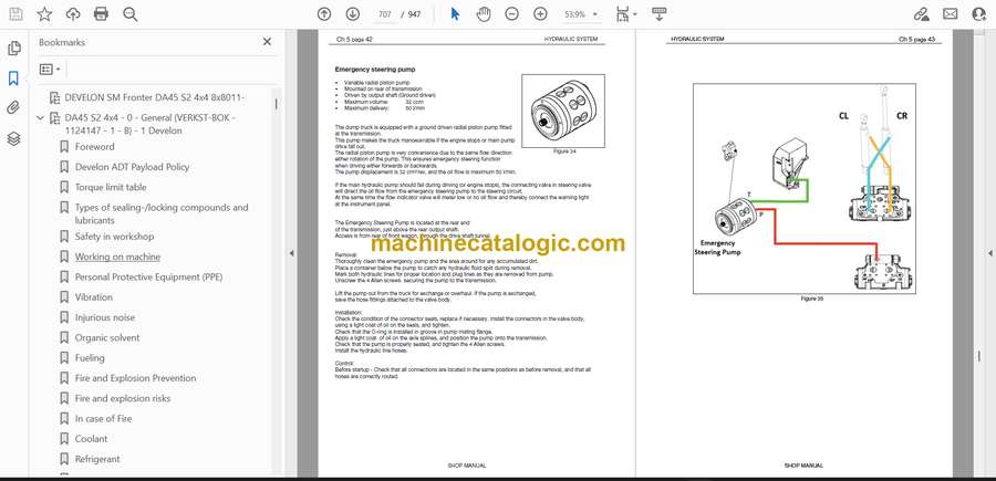
- Emergency steering pump
- Planetary drive “F”
- Separate planetary drive from housing II
- Dismantling planetary drive
- Removal input shaft and clutches
- Separate housing I and housing II
- Housing I
- Differential “G”
- Clutches “V”; “R”; “A”; “B”; “C”; “D”; “E”
- Housing II
- Clutches „V“; „R“; „A“; „B“; „C“; „D“; „E“ and Differential
- Clutch “E”
- Clutch “R”
- Clutch “B“
- Clutch “V“
- Clutch “C“
- Clutch “D“
- Clutch “A“
- Dismantling differential ”G“
- Reassembly of Transmission inner parts
- Clutches „V“; „R“; „A“; „B“; „C“; „D“; „E“ and Differential
- Clutch ”E“
- Clutch “R“
- Clutch “B“
- Clutch “V“
- Clutch “C“
- Clutch “D“
- Clutch “A“
- Check of the disk clearance all clutches
- Assembling differential ”G“
- Installation input shaft and clutches
- Housing II
- Clutches “V”;“R”;“A”;“B”;“C”;“D”;“E”
- Housing I
- Assemble housing I and housing II
- Oil supply
- Shifting block II
- Valve block
- Retarder
- Primary pump
- Installation retarder, primary pump, valve block and shifting block II
- Engine connection
- Planetary drive “F”
- Mount planetary drive to housing II
- Output to front and rear axle
- Output to front axle with axle insert LKV
- Power take-off
- PTO-gear – 1st power take-off
- PTO-input shaft
- Emergency steering pump
- Reassembly of shifting block I and speed sensors:
- Shifting block I
- Refitting of speed sensor n4-output
- Refitting breather, Oil sight level glass, Cover plate and screw plug
- Disassembly of LKV Axle Insert
- Disassembly
- Dismantling multi-disk differential lock
- Disassembling input
- Assembling of LKV Axle Insert
- Installing input
- �Adjusting differential bearing rolling torque and backlash.
- Checking backlash on the slotted nut
- Checking contact pattern
- Assembling output
- Contact pattern examples of Gleason Tooth System
- Field of application:
- Ideal contact pattern:
- Contact pattern setting:
- Flank glossary:
- EXAMPLE 1: DEDENDUM TOOTH POSITION
- EXAMPLE 2: ADDENDUM TOOTH POSITION
- EXAMPLE 3: “LINE” CONTACT PATTERN
- Transmission assembly
- Clutch calibration
- Transmission oil check
- DA45 S2 4×4 – 3 Drive line (VERKST-BOK – 1124151 – 1 – B) – 1 Develon
- Introduction
- General
- Structure of the repair manual
- Denomination of standard dimensions
- Conversion table
- Kessler special tools for DA30
- Driveline components
- Hub assembly/disassembly wheel gear front with brake
- Overwiew of parts
- 1. Assembly of the thrust ring
- 2. Assembly of the spacer ring
- 3. Assembly brake unit
- 4. Prepare and mount wheel hub
- 5. Assembly wheel hub unit
- 6. Prepare the ring gear and the ring gear carrier
- 7. Assembly of the ring gear carrier
- 8. Wheel bearing adjustment
- 9. Assembly sun gear with shaft
- 10. Preparation planetary gear drive
- 11. Assembly of the planetary housing
- 12. Preparation of the cover to the drive flange
- 12. Preparation of the cover to the drive flange
- Disassembly hub assembly
- Dismantling planetary unit
- Disassembly of planetary gear
- Disassembly of sun gear
- Loosening the wheel bearing adjustment nut
- Checking the wheel bearing adjustment nut
- Assembly of the face seal
- Hub assembly/disassembly wheel gear rear with brake
- Overwiew of parts
- Disassembly of planetary gear
- Disassembly of axle shaft with assembled sun gear
- Loosening the wheel bearing adjustment nut
- Checking/Retightening the wheel bearing adjustment nut
- Assembly of the axle shaft with assembled sun gear
- Securing the wheel bearing adjustment nut
- Assembly of planetary gear
- Wet multiple disc brake
- Connections wet multiple disc brake
- Disassembly wet multiple disc brake
- Assembly wet multiple disc brake
- Air gap setting with piston adjustment
- Assembly wet multiple disc brake on the axle
- Test of the cooling oil chamber
- Bleeding the wet multiple disc brake
- Final assembly
- Check the air gap (pressurized)
- Alignment of the discs
- Drive shafts
- Front frame
- Rear frame
- Mounting the bearings on the intermediate shaft (B)
- Mounting brake disk and senor on intermediate shaft (B)
- Brake disc runout
- Front differential and transmission
- Brakes
- Service brake
- Service brake description
- Parking brake
- Troubleshooting the park brake
- Testing of parking brake
- Removal of the linings
- Removal of the park brake unit from dump truck
- Disassembly of the park brake unit.
- Assembly of the park brake unit
- Assembly of the park brake
- Adjustment of the initial caliper clearance
- Disc
- Measure disc thickness
- Lining wear measurement of wet multiple disk brake
- Rear differential
- Overview of parts
- Exchange of the complete rear differential
- Disassembly of differential and carrier assembly
- Loosening the lock nut
- Assembly of differential and carrier assembly
- Adjustment of drive pinion distance
- Sample calculations ( dimensions in mm)
- Assembly of the drive pinion bearing
- Assembly radial seal ring on the drive flange
- Assembly of the cover to the drive flange
- Assembly drive flange
- Assembly lock nut
- Securing of the lock nut
- Assembly of the differential
- Assembly ring gear
- Tightening torque for standard metric threads.
- Assembly tapered roller bearing onto differential housing
- Installation of the pre-assembled differential
- Fastening bearing caps
- Dimension of backlash
- Adjustment of backlash
- Adjustment differential
- Contact pattern adjustment for bevel wheel tooth system
- Locking the bearing adjustment rings
- Preparation axle housing
- Assembly of the differential and carrier assembly onto the axle housing
- General information
- Recommendation for repairs
- Oil change for rear axle and planetary drive(hubs)
- Note:
- DA45 S2 4×4 – 4 Lubrication (VERKST-BOK – 1124152 – 1 – C) – 1
- Lubrication system parts
- Greasing cycles
- Grease pressure switch
- The 5/2 way valve
- The relief valve
- The minimum level switch
- System test
- Introduction
- The single-test cycle
- The continuous-test cycle
- Warning signal
- Maintenance
- Regularly checks of the greasing system
- Bleeding the pump
- Bleeding the system
- Technical data
- Dimensions of the Twin Pump
- DA45 S2 4×4 – 5 Hydraulic system (VERKST-BOK – 1124153 – 1 – C) – 1
- Components, capacities and oil types
- Hydraulic system main function.
- Hydraulic parts view DA30
- Hydraulic System Description
- Hydraulic System Components
- Main Valve Circuit
- Main Valve – List Of Components
- Main Valve – Spare Parts & Torques
- Hydraulic circuit (up to 8X8050)
- Hydraulic circuit (from 8X8051)
- Startup test procedure
- Main Pump
- Pump description
- Test block
- Main pump pressure adjusting
- Main pump pressure adjusting
- Main pump circuit
- Main pump parts list
- Main pump exploded view
- Steering system
- Orbitrol
- Steering valve
- Steering circuit
- Steering Cylinder
- Steering cylinder, sectional drawing.
- Steering cylinder Repair Instructions
- Emergency steering pump
- Tilting system
- Tilt Lever
- View of the tilting system
- Tilt cylinders:
- Tilt cylinder, sectional drawing.
- Tilt cylinder Repair Instructions
- Fan system
- Fan Drive Motor
- Disassemble the fan and fan motor
- Brakes
- Brake circuit view
- General discription
- Parking brake, description
- Parking brake circuit view
- Service brake, description
- Accumulators
- Description of the Accumulators
- Filling table of Correction Factors
- Main valve pressure adjustment:
- Brake cooling system
- VCU3 software calibration
- Wheel arm calibration
- Tilt sensors calibration
- Body angle sensor calibration
- Body lift (A) pressure sensor zero calibration
- Body 0.0t (empty) calibration
- Emergency steering (EMST) pressure sensor zero calibration
- Brake front and rear circuit (BR_F and BR_R) pressure sensor zero calibration
- Procedure for calibrating rear suspension cylinder pressure reading
- Hydraulic BC (Brake Charge) valve pressure to current calibration
- Hydraulic FAN (Cooling fan) valve pressure to current calibration
- CANPC – VCU3 Status → Calibration 1 and Calibration 2 tabs overview
- DA45 S2 4×4 – 6 Electrical system (VERKST-BOK – 1124154 – 1 – B) – 1 Develon
- Safety instructions
- Welding on the dump truck
- Battery hazard prevention
- Diagnostic
- Overview tools
- CanPc
- CanPc setup
- CIF2 interface
- Software update
- VCU software update procedure
- Transmission software update. With CANPC
- Components
- Front wagon
- Rear wagon
- Overview on the inside of the cabin
- Overview on the outside of the cabin
- Battery
- Cabin
- VCU3
- HVAC
- A/C compressor
- Blower control
- Water valve
- Flap motor
- Temperature sensors
- Evaporator temperature sensor
- Pressure sensors
- Radio
- Interior light
- Cigarette lighter
- Speakers
- Doorswitch
- Tip lever
- Driver seat
- Gear selector
- Wiper motor
- Throttle pedal
- LCD Display
- TMS
- Electric mirrors (optional)
- Buzzer
- DC – DC converter
- USB charger
- Park brake switch
- Mirror adjustment switch
- Steering column switch
- Retarder lever
- Diagnostic connector
- Electrical parts involved in hydraulic control
- Test block
- Steering valve
- Main valve
- Parking brake sensor
- Body float sensor
- TPMS (optional)
- Heater (Optional Webasto)
- Lubrication pump
- PM1
- Sensors
- Clogged air filter sensor
- Hydraulic level sensor
- Level sensor
- Proximity sensor
- Rear view camera
- Lights
- Main lights
- Rear lights
- Beacon light
- Direction/Marking Lights
- Work lights
- Marking light for mirrors
- Electrical circuits
- CAN bus
- Wiring routing
- Front frame
- Rear frame
- Cabin
- Electrical diagrams
- Cabin
- Front and rear
- Power, engine and options
- HVAC unit VCU3
- CANbus overview
- DA45 S2 4×4 – 7 Front frame (VERKST-BOK – 1124155 – 1 – C) – 1
- 7.1 Introduction
- Front wheels
- Rear wheels
- 7.2 Front Axle Suspension
- Hydraulic cylinder disassembly
- Hydraulic cylinder reassembly
- Front suspension cylinder repair instructions (up to 8×8015)
- Front suspension cylinder repair instructions (from 8×8016)
- Panhard Bar
- Suspension Bearing
- Cross Tube Bushings
- 7.3 Articulation Hinge System
- Articulation Bearing
- Articulation Bearing assembly
- Bearing Clearance
- Articulation Hinge
- 7.4 Fenders, Mudguards and Bonnet
- Fender RH
- Fender LH
- Mudguard
- Bonnet Lock
- Bonnet
- Bonnet adjustment and control
- Disassembly of the cooling system
- Disassembly of the separate coolers
- Disassembly of the cooling systems hydraulic motor
- Cab Removal
- Cab Ventilation Control Panel
- Cab Ventilation Unit
- Cab Door
- Door Damper Cylinder
- Door sensor
- Steering Column
- Removal/installation of hydraulic tank
- DA45 S2 4×4 – 8 Rear frame (VERKST-BOK – 1124156 – 1 – C) – 1
- Introduction
- Dumper body
- Overview of the dumper body
- Removal of dumper body
- Installation of dumper body
- Tilt bearings
- Removal of rear axle from rear frame
- Safety precautions
- Disassembly
- Complete removal of the rear axle
- Assembly of rear axle and A-frame
- Rear suspension cylinder repair instruction
- DA45 S2 4×4 – 9 Option (VERKST-BOK – 1124157 – 1 – C) – 1
- 9 Optional Equipment
- View of the Exhaust Body Heating System for T4F
- View of the Exhaust Body Heating System for T4F
- Assembly of The Exhaust Body Heating System
- View of the Engine heater
- Engine heater assembly
- Webasto
- Webasto Assembly
- Electrical refuelling system assembly
- Telematic system installation
- Overview
- Installation procedure
- Checking functionality
- DA45 S2 4×4 – 10 Error codes list (VERKST-BOK – 1124149 – 1 – C) – 1
- Blank Page
- Blank Page
- Blank Page
- Blank Page
- Blank Page
- Blank Page
Develon


