Develon DL280-7 Wheel Loader Shop Manual (950106-02247_E_EN)
The DL280-7 usually lives in the rough stuff—quarries, batch plants, waste yards—loading trucks all day and jockeying material. This shop manual is what you want when you’re past simple filters and grease and you’re ready to strip systems down, lay parts out on the bench, and put it all back together without guessing. Say you’ve got a center-pin clunk and a hydraulic leak at the same time—this helps you plan the teardown, trace the problem, inspect every wear surface, then reassemble it so you don’t have to split it again next month.
Applications & Use Cases
- Plan a full axle or differential teardown, so you can route hoses, brace components, and keep shims and bearings in order during reassembly.
- Trace hydraulic issues by isolating sections, checking pressures at suggested points, and verifying cylinder and valve body condition while they’re off the machine.
- Follow general torque sequences on major joints—hub assemblies, articulation, loader frame—so you don’t warp housings or pinch seals.
- Inspect the engine and cooling stack once it’s stripped down, then align brackets, route wiring, and test sensors before you button it up.
- Bleed brakes and steering circuits properly after component swaps, so you don’t chase spongy pedals or twitchy steering later.
FAQ
Q: Is this a downloadable manual I can search on my laptop?
A: Yes, it’s typically a PDF, so you can search by keyword and jump right to the system you’re working on.
Q: Can I print just the pages I need to take out to the loader?
A: You usually can; most folks print the procedures and diagrams for that job, stick them in plastic sleeves, and keep the full file on a tablet or shop PC.
Safety Note
Always support the loader frame and articulated joint with rated stands before you crawl under or loosen any major pins or mounts.
Develon DL280-7 Wheel Loader Index:
- Safety, Specification and Systems Operation
- Wheel Loader Safety
- Safety Instructions
- General
- Transportation
- Operation
- Long Term Storage
- Maintenance
- Environment and Circumstances
- General Specifications
- Safety Instructions
- General
- Component Locations
- Working Range and Dimensions
- Working Capacities
- General Specifications
- Performance Tests
- Preparation for Performance Tests
- Operational Performance Standard Table
- Operational Performance Test
- Approximate Weight of Workload Materials
- Engine Specifications
- Safety Instructions
- Engine Specification
- Engine Performance Curves
- Tightening Torques
- Drivetrain Specifications
- Safety Instructions
- Specification
- Hydraulic Systems Specifications
- Safety Instructions
- Specification
- General Maintenance Instructions
- Safety Instructions
- Welding Precautions and Instructions
- Hydraulic System – General Precautions
- Maintenance Service and Repair Procedure
- Hydraulic System Cleanliness and Oil Leaks
- Cleaning and Inspection
- Hydraulic Pressure Checks
- Standard Torques
- Safety Instructions
- Torque Values for Standard Metric Fasteners
- Torque Values for Standard U.S. Fasteners
- Type 8 Phosphate Coated Hardware
- Torque Values for Hose Clamps
- ORFS Swivel Nut Recommended Torque
- Torque Values for Split Flanges
- Torque Wrench Extension Tools
- Loctite Applications
- Engine
- Safety Instructions
- General Information
- Mechanical System
- Fuel System
- Lubricating System
- Cooling System
- Intake/Exhaust System
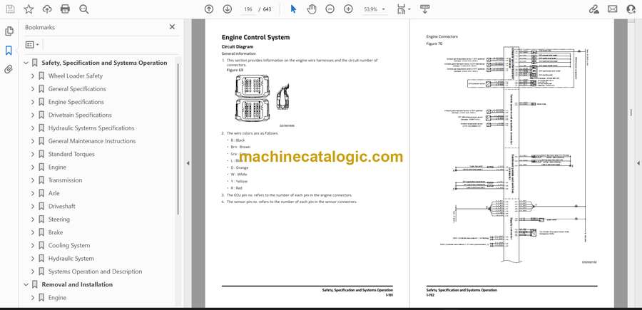
- Engine Control System
- After Treatment System
- Transmission
- Safety Instructions
- Transmission and Torque Converter (4WG)
- Axle
- Safety Instructions
- Front Axle & Rear Axle
- Driveshaft
- Safety Instructions
- General
- Steering
- Safety Instructions
- Power Steering System
- Steering Unit
- Jerk Softener and Accumulator
- Brake
- Safety Instructions
- Service Brake
- Brake and Pilot Supply Valve
- Parking Brake
- Brake Pedal Valve
- Accumulator
- Brake Filter
- Cooling System
- Safety Instructions
- Cooling System
- Fan and Brake Pump
- Fan Motor
- Radiator Assembly
- Hydraulic System
- Safety Instructions
- Main Pump
- Main Control Valve
- Pilot System
- Hydraulic System
- Oil Tank
- Systems Operation and Description
- Safety Instructions
- Power System
- Starting System
- Charging System
- Gauge Panel system
- Parallel Lift
- Electric Steering
- EPOS system
- Air Conditioner System
- Refrigerant System Repairs
- Troubleshooting
- Removal and Installation
- Engine
- Safety Instructions
- Before Removing and Installing
- Engine and Transmission Assembly
- DEF (adblue®) Quality Sensor
- ECU (Engine Control Unit)
- Alternator
- Starter Motor
- Sensors – After Treatment
- V-Belt
- Hydraulic Systems and Structure
- Safety Instructions
- Before Removing and Installing
- Front Axle
- Rear Axle
- Drive Shaft
- Transmission Assembly
- Fuel Tank
- Joystick Valve (Work Lever)
- Cabin Assembly
- Undercovers
- Electric and Electronic
- Safety Instructions
- Before Removing and Installing
- Gauge Panel
- Battery Assembly
- Cabin Switches
- Cabin Photo Sensor
- DC-DC Controller
- Display Monitor
- EPOS Controller
- TCU Controller
- ACU Controller
- Smart Key Controller
- TMS Controller
- Wiper Motor
- Combination Switch
- Transmission Lever
- Troubleshooting Guide
- Wiring Harness Layout
- Safety Instructions
- Wiring Device
- Error Code
- Safety Instructions
- VCU Error Code
- ECU Error Code
- TCU Error Code
- Schematics
- DL280-7 Hydraulic Schematic
- DL220-7/DL250-7/DL250TC-7/DL280-7 Electric Schematic
- Main Harness
- Cabin Harness
Develon


